1
6.3 Performance specifications
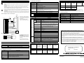
5. Wiring
Item
Cautions on wiring
•
•
•
•
Control method
Two-position control, PID control (with auto tuning function), PI control
Make sure to shut down the power supplies of all phases on the outside before starting installation
or wiring.
If the power supplies are not shut down, you may receive an electrical shock or the unit may be
damaged.
Control operation
period
500ms
Set temperature
range
Equivalent to input range
As to loads, such as a connector for normal rotation and a connector for reverse rotation,
which are dangerous when turning on at the same time, make sure to interlock them outside
the PLC in addition to interlocking of them in a program in the PLC.
Heater disconnection
detection
Alarm is detected by buffer memory
(Variable within range from 0 to 100 A.).
Operation mode
0: Measured value monitor
1: Measured value monitor + Temperature alarm
2: Measured value monitor + Temperature alarm + Control
(selected by buffer memory)
Correctly connect the power cable of the FX2N-2LC and the PLC as described in this manual.
If the AC power supply is connected to a DC I/O terminal or DC power terminal, the PLC may
be damaged.
2
Perform Class 3 grounding with an electric wire of 2 mm or more to the grounding terminal in the
FX2N-2LC and the PLC. However, never perform common grounding with a strong power system.
When a temperature sensor is a thermocouple
-
FX2N-2LC
+
24+
*1
COM
CT
POWER
Lit (green): While 5V power is supplied
Extinguished: While 5V power is not supplied
24V
Lit (red): While 24V power is supplied
Extinguished: While 24V power is not supplied
OUT1
Lit (red): While control output 1 is ON
Extinguished: While control output 1 is OFF
Lit (red): While control output 2 is ON
FG
Shielded cable
Item
Description
Number of input points
Use the compensating cable
when you use the thermo couple.
Input
type
PTB/TC-
Heater
Thermocouple
CT
Temperature input
CT
CT
PTA/
FG
Shielded cable
PTB/TC+
Heater
Thermocouple
PTB/TC-
When a temperature sensor is a resistance thermometer bulb
FX2N-2LC
Shielded cable
•
Resistance
thermometer bulb
PTA/
FG
PTB/TC+
PTB/TC-
•
The temperature sensor must use
three line type.
The resistance of the lead wire is a
little, and use the wire rod without
the resistance difference between
three lines.
Secure the termination using a
tightening torque of 0.5 to 0.8Nžm
CT input
2 points
Thermocouple
K, J, R, S, E, T, B, N, PLII, WRe5-26, U, L
Resistance thermometer bulb
Pt100, JPt100
Measurement precision
Ambient temperature 23 °C ± 5 °C : ± 0.3% of range span ± 1 digit.
Ambient temperature 0 °C to 55 °C : ± 0.7% of range span ± 1 digit.
However, 0 to 399 °C (0 to 799 °F) in B inputs as well as 0 to 32 °F in
PLII and WRe5-26 inputs are outside precision guarantee range.
Cold contact temperature compensation error
Within ±1.0 °C
However, within ± 2.0 °C while input value is -100 to -150 °C
within ± 3.0 °C while input value is -150 to -200 °C
Resolution
0.1 °C (0.1°F) or 1 °C(1°F) (Varies depending on input range of used
sensors.)
Sampling period
500ms
Effect of external resistance
Approx. 0.35 µV/Ω
Item
Other environmental specifications are equivalent to those for the PLC main unit. Refer to the manual of
the PLC main unit.
24V DC (-15% to +10% maximum), input from driving power
supply terminal
Power supply for
communication
5V DC (supplied from inside of PLC main unit)
Current consumption
24V DC, 55 mA and 5V DC, 70 mA
Insulation method
Analog input area and PLC are insulated by photocoupler.
Power supply and analog input are insulated by DC/DC converter.
(Channels are insulated from each other.)
Number of occupied
I/O points
8 points in total (including input points and output points)
JPt100
Rt100
Input range
-50.0 to 150.0 °C
-200.0 to 500.0 °C
-300.0 to 300.0 °F
-300 to 900 °F
-50.0 to 150.0 °C
-200.0 to 600.0 °C
-300.0 to 300.0 °F
-300 to 1100 °F
•
When B is used, 0 to 399 °C (0 to 799 °F) is outside the precision guarantee range.
•
When PLII is used, 0 to 32 °F is outside the precision guarantee range.
When WRe5 to WRe26 are used, 0 to 32 °F is outside the precision guarantee range.
Item
Description
Number of output points
2 points
Output method
Open collector transistor output
Rated load voltage
5 to 24V DC
Maximum load voltage
30V DC or less
Maximum load current
100mA
Leak current in OFF status
0.1 mA or less
Maximum voltage drop in ON status
2.5V (maximum) or 1.0V (typical) at 100 mA
Control output cycle
30 seconds (Variable within range from 1 to 100 seconds)
Allowable input lead wire
resistance
10 Ω or less
•
Operation when input is
disconnected
This manual has been written to be used by trained and competent personnel. This is defined
by the European directives for machinery, low voltage and EMC.
Upscale
•
Operation when input is
short-circuited
Downscale
If in doubt at any stage during the installation of the FX 2N-2LC always consult a professional
electrical engineer who is qualified and trained to the local and national standards. If in doubt
about the operation or use of the FX 2N-2LC please consult the nearest Mitsubishi Electric
distributor.
•
Under no circumstances will Mitsubishi Electric be liable or responsible for any consequential
damage that may arise as a result of the installation or use of this equipment.
•
All examples and diagrams shown in this manual are intended only as an aid to understanding
the text, not to guarantee operation. Mitsubishi Electric will accept no responsibility for actual
use of the product based on these illustrative examples.
•
Owing to the very great variety in possible application of this equipment, you must satisfy
yourself as to its suitability for your specific application.
Guidelines for the safety of the user and protection of the FX2N-2LC
Number of inputs
2 points
Current detector
CTL-12-S36-8 or CTL-6-P-H (manufactured by U.R.D. Co., Ltd.)
Heater current
measurement value
When CTL-12 is used: 0 to 100A
Measurement precision
Larger one between ± 5% of input value and 2 A
(excluding precision of current detector)
Sampling period
1 second
When CTL-6 is used: 0 to 30A
K
J
R
S
-200.0 to 200.0 °C
-100.0 to 400.0 °C
-100 to 1300 °C
-100 to 800 °F
-100 to 2400 °F
-200.0 to 200.0 °C
-200.0 to 400.0 °C
-100.0 to 800.0 °C
-100 to 1200 °C
-100 to 1600 °F
-100 to 2100 °F
0 to 1700 °C
0 to 3200 °F
0 to 1700 °C
0 to 3200 °F
Sensor type
E
T
B
Input range
-200.0 to 200.0 °C
0 to 1000 °C
0 to 1800 °F
-200.0 to 200.0 °C
-200.0 to 400.0 °C
0.0 to 400.0 °C
-300.0 to 400.0 °F
-300.0 to 700.0 °F
0.0 to 700.0 °F
Input range
Specifications
Driving power supply
Sensor type
1 MΩ or more
6.2 Power supply specifications
Item
0.0 to 900.0 °C
0 to 1600 °F
Approx. 0.3 mA
Specifications
500V AC for 1 minute
(between analog input terminal and grounding terminal)
-200.0 to 600.0 °C
-300.0 to 700.0 °F
Sensor current
Sensor type
6.1 Environmental specifications
0 to 2300 °C
0 to 3000 °F
Input impedance
6.5 Input range
6. Specifications
Withstand voltage
Extinguished: While control output 2 is OFF
6.4 Input specifications
PTA/
PTB/TC+
0 to 1200 °C
0 to 2300 °F
•
CT
CT
Input range
6.6 Output specifications
SSR
OUT2
L
Built-in EEPROM (Number of times of overwrite: 100,000 times)
SSR
OUT1
U
Memory
OUT2
•
24-
WRe5-26
Adjustment data check, input value check, watch dog timer check.
Indication
DC24V
PLII
Self-diagnosis
function
AC power
supply
*1 Connect the ground terminals of
the FX2N -2LC unit and the main
unit. Use class 3 grounding on
the main unit.
Sensor type
Description
Manual number : JY992D85601
Manual revision : B
N
Date
0 to 1800 °C
0 to 3000 °F
: MAY 2000
0 to 1300 °C
0 to 2300 °F
HEAD OFFICE : MITSUBISHI DENKI BLDG MARUNOUTI TOKYO 100-8310
HIMEJI WORKS : 840, CHIYODA CHO, HIMEJI, JAPAN
JY992D85601B
TELEX : J24532 CABLE MELCO TOKYO
Effective MAY 2000
Specifications are subject to
change without notice