1
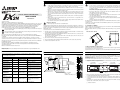
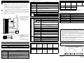
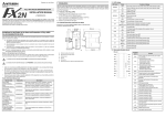
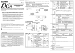
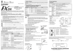
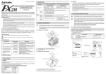
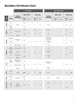
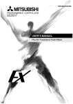
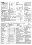
1. Outline of Product Cautions on design Cautions on installation • Install a safety circuit outside the PLC so that the entire system conservatively operates even if an abnormality occurs in the external power supply or a failure occurs in the PLC. If the safety circuit is installed inside the PLC, malfunction and erroneous output may cause accidents. Make sure to construct an emergency stop circuit, protection circuit, interlock circuit to prevent damage to a machine or instrument outside the PLC. • Use the unit in the environment for the general specifications described in the manual. Never use the unit in a place with dust, soot, conductive dust, corrosive gas or flammable gas, a place exposed to high temperature, dew condensation or rain and wind or a place exposed to vibration or impact. If the unit is used in such a place, electrical shock, fire, malfunction, damage in the product or deterioration of the product may be caused. • When the PLC or FX2N-2LC detects an abnormality such as a watch dog timer error or input value error by the self-diagnosis circuit, and all outputs turn off. When an abnormality occurs in the I/O control area which cannot be detected by the CPU in the PLC, output control may be disabled. Design external circuits and the structure so that the entire system conservatively operates in such cases. • Never drop cutting chips or electric wire chips into the ventilation window of the FX2N-2LC while drilling screw holes or wiring cables. Such chips may cause fire, failure or malfunction. • After finishing installation, remove a dust preventing sheet adhered on the ventilation window of the PLC and the FX2N-2LC. If the sheet remains attached, fire, failure or malfunction may be caused. When a failure occurs in a relay, transistor, triac, etc. in the FX2N-2LC or output unit of PLC, outputs may keep ON or OFF. For output signals which may lead to severe accidents, design external circuits and the structure so that the entire system conservatively operates. • Securely connect connection cables such as extension cables and memory cassettes to specified connectors. Imperfect contact may cause malfunction. FX2N-2LC SPECIAL FUNCTION BLOCK USER’S GUIDE JY992D85601E Cautions on Safety (Make sure to read this paragraph before using the unit.) 3. Installation Method • Caution on disposal Thoroughly read this manual, a separate USER’S MANUAL and all attached documents of the connected programmable controller (hereafter referred to as "PLC") and other related units before starting installation, operation and inspection/maintenance of the temperature control block. Acquire the knowledge on equipment, the information on safety and all cautions before using the temperature control block. In this instruction manual, cautions on safety are classified as "WARNING" or "CAUTION". • When disposing of the unit, treat it as industrial waste. This symbol indicates that incorrect handling may generate a dangerous situation which may lead to death or serious injury. The temperature control block FX2N-2LC (hereafter referred to as "temperature control block" or "FX2N-2LC") equipped with two temperature input points and two transistor (open collector) output points is a special block to control outputs of temperature inputs from thermocouples and platinum resistance thermometer bulbs by PID control. Connect the FX2N-2LC to the FX1N/FX2N/FX2NC/FX3U/FX3UC Series PLC. This symbol indicates that incorrect handling may generate a dangerous situation which may lead to medium or minor injury or physical damage. 1) As input sensors, two thermocouples, two platinum resistance thermometer bulbs or one thermocouple and one platinum resistance thermometer bulb are available. Even an item classified as "CAUTION" may lead to a severe result depending on the situation. Each item describes important information. Make sure to observe each item marked with "WARNING" or "CAUTION". Carefully store the instruction manual offered together with the temperature control block so that the operator can refer to it at any time necessary. Make sure to deliver the instruction manual to the end user. The FX2N-2LC can be installed on the right side of an FX1N/FX2N/FX2NC/FX3U/FX3UC Series PLC main unit or extension unit. The FX2N-2LC can be attached with a DIN rail DIN46277 (width: 35 mm) or directly attached to a panel surface with screws (M4). 3.1 Installation on DIN rail Align the upper side of the DIN rail mounting groove of the FX2N-2LC with a DIN rail DIN46277 (width: 35 mm) (➀), and push it on the DIN rail.(➁) When removing the FX2N-2LC, pull out downward the DIN rail mounting hook.(➂), and remove from DIN rail.(➃) When attached to DIN rail 2) Data can be read and written using FROM/TO instructions when the FX2N-2LC is connected to the FX 1N/FX2N/FX2NC/FX3U/FX3UC Series PLC. (The FX 2N-2LC performs arithmetic operation for PID control and output control. The PLC does not have to perform such control.) When removed from DIN rail 3) Disconnection of heaters can be detected by current detection. 4) The proportional band, the integral time and the derivative time can be easily set by auto tuning. We appreciate it very much that you have purchased the temperature control block FX2N-2LC for Mitsubishi programmable controller. This manual describes handling of the MELSEC-F Series Temperature Control Block FX2N-2LC. Thoroughly read this manual and other manuals of related products, and sufficiently understand the specifications before use. Make sure to deliver this manual to the end user. 5) Channels are isolated from each other. 3.2 Direct installation on panel surface Screw-tighten the FX2N-2LC with M4 screws to a panel surface using two (upper and lower) mounting holes provided on the left side of the FX2N-2LC. Assure the interval of 1 to 2 mm between a unit or block installed on the left side of the FX2N-2LC. Brand and product names described by/in this manual are trademarks or registered trademark of the irrespective ownes. Related Manuals 2. Outside Dimension When you using the FX2N-2LC for the first time, a separate FX2N-2LC USER’S MANUAL is required. Make sure to obtain the USER’S MANUAL from the dealer from which you have purchased the FX2N2LC, and safely use the FX2N-2LC. Describes the specification, wiring and installation of FX3U series PLC. 24V OUT1 OUT2 55(2.17) Mounting hole 2-Φ4.5 Describes the specification, wiring and installation of FX3UC series PLC. JY992D88101 Additional Manual Describes the instructions of FX1S/ FX1N/FX2N/FX2NC series PLC. JY997D16601 Additional Manual This manual explains the installations of FX3S/FX3G/FX3GC/FX3U/FX3UC series PLC. If necessary, obtain them from the dealer from which you have purchased the FX2N-2LC. Status indicator LED DIN rail mounting hook Unit : mm (inch) Mass: 0.3kg Terminal screws M3 (0.12) CH2 Additional Manual 87(3.43) TCCT FG PTB TC+ CT PTA PTB JY997D28701 90(3.54) FX2N-2LC DIN rail (width: 35 mm) mounting groove CH1 Additional Manual POWER 80(3.15) Additional Manual Connect the FX2N-2LC to the PLC main unit with an extension cable. FX2N-2LC units are treated as special units of the PLC, and the special unit No. 0 to 7 is automatically assigned to each FX2N-2LC unit from the one nearest to the PLC main unit.*1 (These unit Nos. are used in FROM/TO instructions.) One FX2N-2LC unit occupies eight I/O points in the PLC main unit. For the details of I/O assignment in the PLC, refer to the manual of the PLC main unit. *1 Because the unit No.0 is assigned to the built-in CC-Link/LT master in the FX3UC-32MT-LT, unit numbers assigned to the FX2N-2LC begins with No.1. FX 2N-32MR (X000 to X017) TCCT FG PTB CT PTA TC+ PTB JY997D16501 O Describes the specification, wiring, installation of FX2N-2LC. Describes the specification, wiring JY992D89301 Supplied with product and installation of FX1N series PLC. Describes the specification, wiring JY992D66301 Supplied with product and installation of FX2N series PLC. Describes the specification, wiring JY992D76401 Supplied with product and installation of FX2NC series PLC. JY992D85601 Extension cable 24- OUT1 OUT2 COM 24+ Description Terminal block 24- FX2N-2LC USER’S MANUAL FX1N HARDWARE MANUAL FX2N HARDWARE MANUAL FX2NC HARDWARE MANUAL FX3U Series User’s Manual - Hardware Edition FX3UC Series User’s Manual - Hardware Edition FX SERIES PROGRAMMING MANUAL ΙΙ FX3S/FX3G/FX3GC/FX3U/ FX3UC Series Programming Manual - Basic & Applied Instruction Edition Manual No. Connector for next step extension cable 4(0.16) 24+ Manual name Supplied with product or separately supplied 4. Connection to PLC Main Unit L COM 24+ N X1 X2 X3 X4 X7 IN X10 0 FX 2N-2LC FX 2N-4AD X14 X16 X13 X15 1 2 3 4 5 6 L N FX 2N-2LC X0 COM X2 X4 X6 X0 X2 X4 X6 X5 24+ X1 X3 X7 X1 X3 X5 X7 POWER POWER 7 10 11 12 13 14 15 16 17 FX 2N-32ER (X020 to X037) IN POWER 0 1 2 3 4 5 6 7 0 1 2 3 4 5 6 7 0 1 2 3 4 5 6 7 0 1 2 3 4 5 6 7 POWER POWER RUN BATT.V PROG.E FX2N-32MR Y1 Y2 Y3 Y4 Y5 Y6 OUT 0 1 2 (Y000 to Y017) • • • • 3 4 5 6 7 10 11 12 13 14 15 16 17 Y10 Y12 COM3 Y11 Y13 CPU.E FX2N-2LC FX2N-4AD FX2N-32ER Y0 Y2 COM1 Y1 Y3 Y14 Y15 Y4 Y6 COM2 Y5 Y7 OUT Y0 Y2 COM3 Y1 Y3 FX2N-2LC Y4 Y6 COM4 Y5 Y7 24V 24V 24V OUT1 OUT1 A/D OUT2 OUT2 Special block Special block No. 1 No. 0 (Y020 to Y037) Special block No.2 Please check power supply specifications to decide the number of FX2N-2LC units that can be connected to the FX1N/FX2N/FX2NC/FX3U/FX3UC extension unit and PLC. To connect the FX2N-2LC unit to the FX2NC Series PLC, the interface FX2NC-CNV-IF is required. To connect the FX2N-2LC unit to the FX3UC Series PLC, the interface FX2NC-CNV-IF or FX3UC-1PS-5V is required. For extension, an extension cable FX0N-65EC (650 mm) and the FX2N-CNV-BC sold separately are required. Only one FX0N-65EC can be used in one system. ( ) indicates the I/O No. 1. Outline of Product Cautions on design Cautions on installation • Install a safety circuit outside the PLC so that the entire system conservatively operates even if an abnormality occurs in the external power supply or a failure occurs in the PLC. If the safety circuit is installed inside the PLC, malfunction and erroneous output may cause accidents. Make sure to construct an emergency stop circuit, protection circuit, interlock circuit to prevent damage to a machine or instrument outside the PLC. • Use the unit in the environment for the general specifications described in the manual. Never use the unit in a place with dust, soot, conductive dust, corrosive gas or flammable gas, a place exposed to high temperature, dew condensation or rain and wind or a place exposed to vibration or impact. If the unit is used in such a place, electrical shock, fire, malfunction, damage in the product or deterioration of the product may be caused. • When the PLC or FX2N-2LC detects an abnormality such as a watch dog timer error or input value error by the self-diagnosis circuit, and all outputs turn off. When an abnormality occurs in the I/O control area which cannot be detected by the CPU in the PLC, output control may be disabled. Design external circuits and the structure so that the entire system conservatively operates in such cases. • Never drop cutting chips or electric wire chips into the ventilation window of the FX2N-2LC while drilling screw holes or wiring cables. Such chips may cause fire, failure or malfunction. • After finishing installation, remove a dust preventing sheet adhered on the ventilation window of the PLC and the FX2N-2LC. If the sheet remains attached, fire, failure or malfunction may be caused. When a failure occurs in a relay, transistor, triac, etc. in the FX2N-2LC or output unit of PLC, outputs may keep ON or OFF. For output signals which may lead to severe accidents, design external circuits and the structure so that the entire system conservatively operates. • Securely connect connection cables such as extension cables and memory cassettes to specified connectors. Imperfect contact may cause malfunction. FX2N-2LC SPECIAL FUNCTION BLOCK USER’S GUIDE JY992D85601E Cautions on Safety (Make sure to read this paragraph before using the unit.) 3. Installation Method • Caution on disposal Thoroughly read this manual, a separate USER’S MANUAL and all attached documents of the connected programmable controller (hereafter referred to as "PLC") and other related units before starting installation, operation and inspection/maintenance of the temperature control block. Acquire the knowledge on equipment, the information on safety and all cautions before using the temperature control block. In this instruction manual, cautions on safety are classified as "WARNING" or "CAUTION". • When disposing of the unit, treat it as industrial waste. This symbol indicates that incorrect handling may generate a dangerous situation which may lead to death or serious injury. The temperature control block FX2N-2LC (hereafter referred to as "temperature control block" or "FX2N-2LC") equipped with two temperature input points and two transistor (open collector) output points is a special block to control outputs of temperature inputs from thermocouples and platinum resistance thermometer bulbs by PID control. Connect the FX2N-2LC to the FX1N/FX2N/FX2NC/FX3U/FX3UC Series PLC. This symbol indicates that incorrect handling may generate a dangerous situation which may lead to medium or minor injury or physical damage. 1) As input sensors, two thermocouples, two platinum resistance thermometer bulbs or one thermocouple and one platinum resistance thermometer bulb are available. Even an item classified as "CAUTION" may lead to a severe result depending on the situation. Each item describes important information. Make sure to observe each item marked with "WARNING" or "CAUTION". Carefully store the instruction manual offered together with the temperature control block so that the operator can refer to it at any time necessary. Make sure to deliver the instruction manual to the end user. The FX2N-2LC can be installed on the right side of an FX1N/FX2N/FX2NC/FX3U/FX3UC Series PLC main unit or extension unit. The FX2N-2LC can be attached with a DIN rail DIN46277 (width: 35 mm) or directly attached to a panel surface with screws (M4). 3.1 Installation on DIN rail Align the upper side of the DIN rail mounting groove of the FX2N-2LC with a DIN rail DIN46277 (width: 35 mm) (➀), and push it on the DIN rail.(➁) When removing the FX2N-2LC, pull out downward the DIN rail mounting hook.(➂), and remove from DIN rail.(➃) When attached to DIN rail 2) Data can be read and written using FROM/TO instructions when the FX2N-2LC is connected to the FX 1N/FX2N/FX2NC/FX3U/FX3UC Series PLC. (The FX 2N-2LC performs arithmetic operation for PID control and output control. The PLC does not have to perform such control.) When removed from DIN rail 3) Disconnection of heaters can be detected by current detection. 4) The proportional band, the integral time and the derivative time can be easily set by auto tuning. We appreciate it very much that you have purchased the temperature control block FX2N-2LC for Mitsubishi programmable controller. This manual describes handling of the MELSEC-F Series Temperature Control Block FX2N-2LC. Thoroughly read this manual and other manuals of related products, and sufficiently understand the specifications before use. Make sure to deliver this manual to the end user. 5) Channels are isolated from each other. 3.2 Direct installation on panel surface Screw-tighten the FX2N-2LC with M4 screws to a panel surface using two (upper and lower) mounting holes provided on the left side of the FX2N-2LC. Assure the interval of 1 to 2 mm between a unit or block installed on the left side of the FX2N-2LC. Brand and product names described by/in this manual are trademarks or registered trademark of the irrespective ownes. Related Manuals 2. Outside Dimension When you using the FX2N-2LC for the first time, a separate FX2N-2LC USER’S MANUAL is required. Make sure to obtain the USER’S MANUAL from the dealer from which you have purchased the FX2N2LC, and safely use the FX2N-2LC. Describes the specification, wiring and installation of FX3U series PLC. 24V OUT1 OUT2 55(2.17) Mounting hole 2-Φ4.5 Describes the specification, wiring and installation of FX3UC series PLC. JY992D88101 Additional Manual Describes the instructions of FX1S/ FX1N/FX2N/FX2NC series PLC. JY997D16601 Additional Manual This manual explains the installations of FX3S/FX3G/FX3GC/FX3U/FX3UC series PLC. If necessary, obtain them from the dealer from which you have purchased the FX2N-2LC. Status indicator LED DIN rail mounting hook Unit : mm (inch) Mass: 0.3kg Terminal screws M3 (0.12) CH2 Additional Manual 87(3.43) TCCT FG PTB TC+ CT PTA PTB JY997D28701 90(3.54) FX2N-2LC DIN rail (width: 35 mm) mounting groove CH1 Additional Manual POWER 80(3.15) Additional Manual Connect the FX2N-2LC to the PLC main unit with an extension cable. FX2N-2LC units are treated as special units of the PLC, and the special unit No. 0 to 7 is automatically assigned to each FX2N-2LC unit from the one nearest to the PLC main unit.*1 (These unit Nos. are used in FROM/TO instructions.) One FX2N-2LC unit occupies eight I/O points in the PLC main unit. For the details of I/O assignment in the PLC, refer to the manual of the PLC main unit. *1 Because the unit No.0 is assigned to the built-in CC-Link/LT master in the FX3UC-32MT-LT, unit numbers assigned to the FX2N-2LC begins with No.1. FX 2N-32MR (X000 to X017) TCCT FG PTB CT PTA TC+ PTB JY997D16501 O Describes the specification, wiring, installation of FX2N-2LC. Describes the specification, wiring JY992D89301 Supplied with product and installation of FX1N series PLC. Describes the specification, wiring JY992D66301 Supplied with product and installation of FX2N series PLC. Describes the specification, wiring JY992D76401 Supplied with product and installation of FX2NC series PLC. JY992D85601 Extension cable 24- OUT1 OUT2 COM 24+ Description Terminal block 24- FX2N-2LC USER’S MANUAL FX1N HARDWARE MANUAL FX2N HARDWARE MANUAL FX2NC HARDWARE MANUAL FX3U Series User’s Manual - Hardware Edition FX3UC Series User’s Manual - Hardware Edition FX SERIES PROGRAMMING MANUAL ΙΙ FX3S/FX3G/FX3GC/FX3U/ FX3UC Series Programming Manual - Basic & Applied Instruction Edition Manual No. Connector for next step extension cable 4(0.16) 24+ Manual name Supplied with product or separately supplied 4. Connection to PLC Main Unit L COM 24+ N X1 X2 X3 X4 X7 IN X10 0 FX 2N-2LC FX 2N-4AD X14 X16 X13 X15 1 2 3 4 5 6 L N FX 2N-2LC X0 COM X2 X4 X6 X0 X2 X4 X6 X5 24+ X1 X3 X7 X1 X3 X5 X7 POWER POWER 7 10 11 12 13 14 15 16 17 FX 2N-32ER (X020 to X037) IN POWER 0 1 2 3 4 5 6 7 0 1 2 3 4 5 6 7 0 1 2 3 4 5 6 7 0 1 2 3 4 5 6 7 POWER POWER RUN BATT.V PROG.E FX2N-32MR Y1 Y2 Y3 Y4 Y5 Y6 OUT 0 1 2 (Y000 to Y017) • • • • 3 4 5 6 7 10 11 12 13 14 15 16 17 Y10 Y12 COM3 Y11 Y13 CPU.E FX2N-2LC FX2N-4AD FX2N-32ER Y0 Y2 COM1 Y1 Y3 Y14 Y15 Y4 Y6 COM2 Y5 Y7 OUT Y0 Y2 COM3 Y1 Y3 FX2N-2LC Y4 Y6 COM4 Y5 Y7 24V 24V 24V OUT1 OUT1 A/D OUT2 OUT2 Special block Special block No. 1 No. 0 (Y020 to Y037) Special block No.2 Please check power supply specifications to decide the number of FX2N-2LC units that can be connected to the FX1N/FX2N/FX2NC/FX3U/FX3UC extension unit and PLC. To connect the FX2N-2LC unit to the FX2NC Series PLC, the interface FX2NC-CNV-IF is required. To connect the FX2N-2LC unit to the FX3UC Series PLC, the interface FX2NC-CNV-IF or FX3UC-1PS-5V is required. For extension, an extension cable FX0N-65EC (650 mm) and the FX2N-CNV-BC sold separately are required. Only one FX0N-65EC can be used in one system. ( ) indicates the I/O No. 1. Outline of Product Cautions on design Cautions on installation • Install a safety circuit outside the PLC so that the entire system conservatively operates even if an abnormality occurs in the external power supply or a failure occurs in the PLC. If the safety circuit is installed inside the PLC, malfunction and erroneous output may cause accidents. Make sure to construct an emergency stop circuit, protection circuit, interlock circuit to prevent damage to a machine or instrument outside the PLC. • Use the unit in the environment for the general specifications described in the manual. Never use the unit in a place with dust, soot, conductive dust, corrosive gas or flammable gas, a place exposed to high temperature, dew condensation or rain and wind or a place exposed to vibration or impact. If the unit is used in such a place, electrical shock, fire, malfunction, damage in the product or deterioration of the product may be caused. • When the PLC or FX2N-2LC detects an abnormality such as a watch dog timer error or input value error by the self-diagnosis circuit, and all outputs turn off. When an abnormality occurs in the I/O control area which cannot be detected by the CPU in the PLC, output control may be disabled. Design external circuits and the structure so that the entire system conservatively operates in such cases. • Never drop cutting chips or electric wire chips into the ventilation window of the FX2N-2LC while drilling screw holes or wiring cables. Such chips may cause fire, failure or malfunction. • After finishing installation, remove a dust preventing sheet adhered on the ventilation window of the PLC and the FX2N-2LC. If the sheet remains attached, fire, failure or malfunction may be caused. When a failure occurs in a relay, transistor, triac, etc. in the FX2N-2LC or output unit of PLC, outputs may keep ON or OFF. For output signals which may lead to severe accidents, design external circuits and the structure so that the entire system conservatively operates. • Securely connect connection cables such as extension cables and memory cassettes to specified connectors. Imperfect contact may cause malfunction. FX2N-2LC SPECIAL FUNCTION BLOCK USER’S GUIDE JY992D85601E Cautions on Safety (Make sure to read this paragraph before using the unit.) 3. Installation Method • Caution on disposal Thoroughly read this manual, a separate USER’S MANUAL and all attached documents of the connected programmable controller (hereafter referred to as "PLC") and other related units before starting installation, operation and inspection/maintenance of the temperature control block. Acquire the knowledge on equipment, the information on safety and all cautions before using the temperature control block. In this instruction manual, cautions on safety are classified as "WARNING" or "CAUTION". • When disposing of the unit, treat it as industrial waste. This symbol indicates that incorrect handling may generate a dangerous situation which may lead to death or serious injury. The temperature control block FX2N-2LC (hereafter referred to as "temperature control block" or "FX2N-2LC") equipped with two temperature input points and two transistor (open collector) output points is a special block to control outputs of temperature inputs from thermocouples and platinum resistance thermometer bulbs by PID control. Connect the FX2N-2LC to the FX1N/FX2N/FX2NC/FX3U/FX3UC Series PLC. This symbol indicates that incorrect handling may generate a dangerous situation which may lead to medium or minor injury or physical damage. 1) As input sensors, two thermocouples, two platinum resistance thermometer bulbs or one thermocouple and one platinum resistance thermometer bulb are available. Even an item classified as "CAUTION" may lead to a severe result depending on the situation. Each item describes important information. Make sure to observe each item marked with "WARNING" or "CAUTION". Carefully store the instruction manual offered together with the temperature control block so that the operator can refer to it at any time necessary. Make sure to deliver the instruction manual to the end user. The FX2N-2LC can be installed on the right side of an FX1N/FX2N/FX2NC/FX3U/FX3UC Series PLC main unit or extension unit. The FX2N-2LC can be attached with a DIN rail DIN46277 (width: 35 mm) or directly attached to a panel surface with screws (M4). 3.1 Installation on DIN rail Align the upper side of the DIN rail mounting groove of the FX2N-2LC with a DIN rail DIN46277 (width: 35 mm) (➀), and push it on the DIN rail.(➁) When removing the FX2N-2LC, pull out downward the DIN rail mounting hook.(➂), and remove from DIN rail.(➃) When attached to DIN rail 2) Data can be read and written using FROM/TO instructions when the FX2N-2LC is connected to the FX 1N/FX2N/FX2NC/FX3U/FX3UC Series PLC. (The FX 2N-2LC performs arithmetic operation for PID control and output control. The PLC does not have to perform such control.) When removed from DIN rail 3) Disconnection of heaters can be detected by current detection. 4) The proportional band, the integral time and the derivative time can be easily set by auto tuning. We appreciate it very much that you have purchased the temperature control block FX2N-2LC for Mitsubishi programmable controller. This manual describes handling of the MELSEC-F Series Temperature Control Block FX2N-2LC. Thoroughly read this manual and other manuals of related products, and sufficiently understand the specifications before use. Make sure to deliver this manual to the end user. 5) Channels are isolated from each other. 3.2 Direct installation on panel surface Screw-tighten the FX2N-2LC with M4 screws to a panel surface using two (upper and lower) mounting holes provided on the left side of the FX2N-2LC. Assure the interval of 1 to 2 mm between a unit or block installed on the left side of the FX2N-2LC. Brand and product names described by/in this manual are trademarks or registered trademark of the irrespective ownes. Related Manuals 2. Outside Dimension When you using the FX2N-2LC for the first time, a separate FX2N-2LC USER’S MANUAL is required. Make sure to obtain the USER’S MANUAL from the dealer from which you have purchased the FX2N2LC, and safely use the FX2N-2LC. Describes the specification, wiring and installation of FX3U series PLC. 24V OUT1 OUT2 55(2.17) Mounting hole 2-Φ4.5 Describes the specification, wiring and installation of FX3UC series PLC. JY992D88101 Additional Manual Describes the instructions of FX1S/ FX1N/FX2N/FX2NC series PLC. JY997D16601 Additional Manual This manual explains the installations of FX3S/FX3G/FX3GC/FX3U/FX3UC series PLC. If necessary, obtain them from the dealer from which you have purchased the FX2N-2LC. Status indicator LED DIN rail mounting hook Unit : mm (inch) Mass: 0.3kg Terminal screws M3 (0.12) CH2 Additional Manual 87(3.43) TCCT FG PTB TC+ CT PTA PTB JY997D28701 90(3.54) FX2N-2LC DIN rail (width: 35 mm) mounting groove CH1 Additional Manual POWER 80(3.15) Additional Manual Connect the FX2N-2LC to the PLC main unit with an extension cable. FX2N-2LC units are treated as special units of the PLC, and the special unit No. 0 to 7 is automatically assigned to each FX2N-2LC unit from the one nearest to the PLC main unit.*1 (These unit Nos. are used in FROM/TO instructions.) One FX2N-2LC unit occupies eight I/O points in the PLC main unit. For the details of I/O assignment in the PLC, refer to the manual of the PLC main unit. *1 Because the unit No.0 is assigned to the built-in CC-Link/LT master in the FX3UC-32MT-LT, unit numbers assigned to the FX2N-2LC begins with No.1. FX 2N-32MR (X000 to X017) TCCT FG PTB CT PTA TC+ PTB JY997D16501 O Describes the specification, wiring, installation of FX2N-2LC. Describes the specification, wiring JY992D89301 Supplied with product and installation of FX1N series PLC. Describes the specification, wiring JY992D66301 Supplied with product and installation of FX2N series PLC. Describes the specification, wiring JY992D76401 Supplied with product and installation of FX2NC series PLC. JY992D85601 Extension cable 24- OUT1 OUT2 COM 24+ Description Terminal block 24- FX2N-2LC USER’S MANUAL FX1N HARDWARE MANUAL FX2N HARDWARE MANUAL FX2NC HARDWARE MANUAL FX3U Series User’s Manual - Hardware Edition FX3UC Series User’s Manual - Hardware Edition FX SERIES PROGRAMMING MANUAL ΙΙ FX3S/FX3G/FX3GC/FX3U/ FX3UC Series Programming Manual - Basic & Applied Instruction Edition Manual No. Connector for next step extension cable 4(0.16) 24+ Manual name Supplied with product or separately supplied 4. Connection to PLC Main Unit L COM 24+ N X1 X2 X3 X4 X7 IN X10 0 FX 2N-2LC FX 2N-4AD X14 X16 X13 X15 1 2 3 4 5 6 L N FX 2N-2LC X0 COM X2 X4 X6 X0 X2 X4 X6 X5 24+ X1 X3 X7 X1 X3 X5 X7 POWER POWER 7 10 11 12 13 14 15 16 17 FX 2N-32ER (X020 to X037) IN POWER 0 1 2 3 4 5 6 7 0 1 2 3 4 5 6 7 0 1 2 3 4 5 6 7 0 1 2 3 4 5 6 7 POWER POWER RUN BATT.V PROG.E FX2N-32MR Y1 Y2 Y3 Y4 Y5 Y6 OUT 0 1 2 (Y000 to Y017) • • • • 3 4 5 6 7 10 11 12 13 14 15 16 17 Y10 Y12 COM3 Y11 Y13 CPU.E FX2N-2LC FX2N-4AD FX2N-32ER Y0 Y2 COM1 Y1 Y3 Y14 Y15 Y4 Y6 COM2 Y5 Y7 OUT Y0 Y2 COM3 Y1 Y3 FX2N-2LC Y4 Y6 COM4 Y5 Y7 24V 24V 24V OUT1 OUT1 A/D OUT2 OUT2 Special block Special block No. 1 No. 0 (Y020 to Y037) Special block No.2 Please check power supply specifications to decide the number of FX2N-2LC units that can be connected to the FX1N/FX2N/FX2NC/FX3U/FX3UC extension unit and PLC. To connect the FX2N-2LC unit to the FX2NC Series PLC, the interface FX2NC-CNV-IF is required. To connect the FX2N-2LC unit to the FX3UC Series PLC, the interface FX2NC-CNV-IF or FX3UC-1PS-5V is required. For extension, an extension cable FX0N-65EC (650 mm) and the FX2N-CNV-BC sold separately are required. Only one FX0N-65EC can be used in one system. ( ) indicates the I/O No. 6.3 Performance specifications 5. Wiring Item Cautions on wiring Control method Two-position control, PID control (with auto tuning function), PI control • Control operation period 500ms Set temperature range Equivalent to input range Heater disconnection detection Alarm is detected by buffer memory (Variable within range from 0.0 to 100.0 A.). Operation mode 0: Measured value monitor 1: Measured value monitor + Temperature alarm 2: Measured value monitor + Temperature alarm + Control (selected by buffer memory) • • • Make sure to shut down the power supplies of all phases on the outside before starting installation or wiring. If the power supplies are not shut down, you may receive an electrical shock or the unit may be damaged. As to loads, such as a connector for normal rotation and a connector for reverse rotation, which are dangerous when turning on at the same time, make sure to interlock them outside the PLC in addition to interlocking of them in a program in the PLC. Correctly connect the power cable of the FX2N-2LC and the PLC as described in this manual. If the AC power supply is connected to a DC I/O terminal or DC power terminal, the PLC may be damaged. Perform Class D grounding with an electric wire of 2 mm2 or more to the grounding terminal in the FX2N-2LC and the PLC. However, never perform common grounding with a strong power system. When a temperature sensor is a thermocouple Self-diagnosis function Adjustment data check, input value check, watch dog timer check. Memory Built-in EEPROM (Number of times of overwrite: 100,000 times) Indication AC power supply *1 Connect the ground terminals of the FX 2N-2LC unit and the main unit. Use class D grounding on the main unit. DC24V - FX2N-2LC + 24+ • 24*1 COM OUT2 CT FG Shielded cable PTB/TC+ PTB/TC- Heater CT CT CT PTA/ FG Shielded cable PTB/TC+ Heater Thermocouple PTB/TC- When a temperature sensor is a resistance thermometer bulb FX2N-2LC Shielded cable • Resistance thermometer bulb PTA/ FG PTB/TC+ PTB/TC- • The temperature sensor must use three line type. The resistance of the lead wire is a little, and use the wire rod without the resistance difference between three lines. Secure the termination using a tightening torque of 0.5 to 0.8Nxm CT input 0 to 1200 °C 0 to 2300 °F 0 to 2300 °C 0 to 3000 °F -200.0 to 600.0 °C -300.0 to 700.0 °F 0.0 to 900.0 °C 0 to 1600 °F Sensor type JPt100 Pt100 Input range -50.0 to 150.0 °C -200.0 to 500.0 °C -300.0 to 300.0 °F -300 to 900 °F -50.0 to 150.0 °C -200.0 to 600.0 °C -300.0 to 300.0 °F -300 to 1100 °F • When B is used, 0 to 399 °C (0 to 799 °F) is outside the precision guarantee range. • When PLII is used, 0 to 32 °F is outside the precision guarantee range. • When WRe5-26 is used, 0 to 32 °F is outside the precision guarantee range. 6.6 Output specifications Extinguished: While 24V power is not supplied OUT1 Lit (red): While control output 1 is ON Extinguished: While control output 1 is OFF Number of output points 2 points OUT2 Lit (red): While control output 2 is ON Extinguished: While control output 2 is OFF Output method Open collector transistor output Rated load voltage 5 to 24V DC Maximum load voltage 30V DC or less Description Item Description 2 points Maximum load current 100mA Thermocouple K, J, R, S, E, T, B, N, PLII, WRe5-26, U, L, JIS C 1602-1995 Leak current in OFF status 0.1 mA or less Resistance thermometer bulb 3-wire Pt100 JIS C 1604-1997, JPt100 JIS C 1604-1981 Maximum voltage drop in ON status 2.5V (maximum) or 1.0V (typical) at 100 mA 30 seconds (Variable within range from 1 to 100 seconds) Measurement precision Ambient temperature 23 °C ± 5 °C : ± 0.3% of range span ± 1 digit. Ambient temperature 0 °C to 55 °C : ± 0.7% of range span ± 1 digit. However, 0 to 399 °C (0 to 799 °F) in B inputs as well as 0 to 32 °F in PLII and WRe5-26 inputs are outside precision guarantee range. Control output cycle Cold contact temperature compensation error Within ±1.0 °C However, within ± 2.0 °C while input value is -150 to -100 °C within ± 3.0 °C while input value is -200 to -150 °C Resolution 0.1 °C (0.1°F) or 1 °C(1°F) (Varies depending on input range of used sensors.) Sampling period 500ms Effect of external resistance Approx. 0.35 μV/Ω Input impedance 1 MΩ or more Sensor current Approx. 0.3 mA Allowable input lead wire resistance 10 Ω or less Operation when input is disconnected Upscale Operation when input is short-circuited Downscale Number of inputs 2 points Current detector CTL-12-S36-8 or CTL-6-P-H (manufactured by U.R.D. Co., Ltd.) Heater current measurement value When CTL-12 is used: 0 to 100A Measurement precision Larger one between ± 5% of input value and 2 A (excluding precision of current detector) Sampling period 1 second Input type Temperature input Thermocouple Input range Lit (red): While 24V power is supplied Number of input points PTA/ L 24V CT CT U Extinguished: While 5V power is not supplied Item SSR WRe5-26 Lit (green): While 5V power is supplied SSR OUT1 PLII POWER 6.4 Input specifications Use the compensating cable when you use the thermo couple. Sensor type Description Guidelines for the safety of the user and protection of the FX2N-2LC • This manual has been written to be used by trained and competent personnel. This is defined by the European directives for machinery, low voltage and EMC. • If in doubt at any stage during the installation of the FX2N-2LC always consult a professional electrical engineer who is qualified and trained to the local and national standards. If in doubt about the operation or use of the FX2N-2LC please consult the nearest Mitsubishi Electric distributor. • Under no circumstances will Mitsubishi Electric be liable or responsible for any consequential damage that may arise as a result of the installation or use of this equipment. • All examples and diagrams shown in this manual are intended only as an aid to understanding the text, not to guarantee operation. Mitsubishi Electric will accept no responsibility for actual use of the product based on these illustrative examples. • Owing to the very great variety in possible application of this equipment, you must satisfy yourself as to its suitability for your specific application. When CTL-6 is used: 0 to 30A 6.5 Input range 6. Specifications Sensor type K J R S Input range -200.0 to 200.0 °C -100.0 to 400.0 °C -100 to 1300 °C -100 to 800 °F -100 to 2400 °F -200.0 to 200.0 °C -100.0 to 400.0 °C -100.0 to 800.0 °C -100 to 1200 °C -100 to 1600 °F -100 to 2100 °F 0 to 1700 °C 0 to 3200 °F 0 to 1700 °C 0 to 3200 °F Sensor type E T B N -200.0 to 200.0 °C 0 to 1000 °C 0 to 1800 °F -200.0 to 200.0 °C -200.0 to 400.0 °C 0.0 to 400.0 °C -300.0 to 400.0 °F -300.0 to 700.0 °F 0.0 to 700.0 °F 6.1 General specifications Item Withstand voltage Specifications 500V AC for 1 minute (between analog input terminal and grounding terminal) Other General specifications are equivalent to those for the PLC main unit. Refer to the manual of the PLC main unit. 6.2 Power supply specifications Item Specifications Driving power supply 24V DC (-15% to +10% maximum), input from driving power supply terminal Power supply for communication 5V DC (supplied from inside of PLC main unit) Current consumption 24V DC, 55 mA and 5V DC, 70 mA Insulation method Analog input area and PLC are insulated by photocoupler. Power supply and analog input are insulated by DC/DC converter. (Channels are insulated from each other.) Number of occupied I/O points 8 points in total (including input points and output points) Input range This manual confers no industrial property rights or any rights of any other kind, nor does it confer any patent licenses. Mitsubishi Electric Corporation cannot be held responsible for any problems involving industrial property rights which may occur as a result of using the contents noted in this manual. Manual number : JY992D85601 Manual revision : E 0 to 1800 °C 0 to 3000 °F Date 0 to 1300 °C 0 to 2300 °F HEAD OFFICE JY992D85601E : April 2015 : TOKYO BUILDING, 2-7-3 MARUNOUCHI, CHIYODA-KU, TOKYO 100-8310, JAPAN Effective April 2015 Specifications are subject to change without notice 6.3 Performance specifications 5. Wiring Item Cautions on wiring Control method Two-position control, PID control (with auto tuning function), PI control • Control operation period 500ms Set temperature range Equivalent to input range Heater disconnection detection Alarm is detected by buffer memory (Variable within range from 0.0 to 100.0 A.). Operation mode 0: Measured value monitor 1: Measured value monitor + Temperature alarm 2: Measured value monitor + Temperature alarm + Control (selected by buffer memory) • • • Make sure to shut down the power supplies of all phases on the outside before starting installation or wiring. If the power supplies are not shut down, you may receive an electrical shock or the unit may be damaged. As to loads, such as a connector for normal rotation and a connector for reverse rotation, which are dangerous when turning on at the same time, make sure to interlock them outside the PLC in addition to interlocking of them in a program in the PLC. Correctly connect the power cable of the FX2N-2LC and the PLC as described in this manual. If the AC power supply is connected to a DC I/O terminal or DC power terminal, the PLC may be damaged. Perform Class D grounding with an electric wire of 2 mm2 or more to the grounding terminal in the FX2N-2LC and the PLC. However, never perform common grounding with a strong power system. When a temperature sensor is a thermocouple Self-diagnosis function Adjustment data check, input value check, watch dog timer check. Memory Built-in EEPROM (Number of times of overwrite: 100,000 times) Indication AC power supply *1 Connect the ground terminals of the FX 2N-2LC unit and the main unit. Use class D grounding on the main unit. DC24V - FX2N-2LC + 24+ • 24*1 COM OUT2 CT FG Shielded cable PTB/TC+ PTB/TC- Heater CT CT CT PTA/ FG Shielded cable PTB/TC+ Heater Thermocouple PTB/TC- When a temperature sensor is a resistance thermometer bulb FX2N-2LC Shielded cable • Resistance thermometer bulb PTA/ FG PTB/TC+ PTB/TC- • The temperature sensor must use three line type. The resistance of the lead wire is a little, and use the wire rod without the resistance difference between three lines. Secure the termination using a tightening torque of 0.5 to 0.8Nxm CT input 0 to 1200 °C 0 to 2300 °F 0 to 2300 °C 0 to 3000 °F -200.0 to 600.0 °C -300.0 to 700.0 °F 0.0 to 900.0 °C 0 to 1600 °F Sensor type JPt100 Pt100 Input range -50.0 to 150.0 °C -200.0 to 500.0 °C -300.0 to 300.0 °F -300 to 900 °F -50.0 to 150.0 °C -200.0 to 600.0 °C -300.0 to 300.0 °F -300 to 1100 °F • When B is used, 0 to 399 °C (0 to 799 °F) is outside the precision guarantee range. • When PLII is used, 0 to 32 °F is outside the precision guarantee range. • When WRe5-26 is used, 0 to 32 °F is outside the precision guarantee range. 6.6 Output specifications Extinguished: While 24V power is not supplied OUT1 Lit (red): While control output 1 is ON Extinguished: While control output 1 is OFF Number of output points 2 points OUT2 Lit (red): While control output 2 is ON Extinguished: While control output 2 is OFF Output method Open collector transistor output Rated load voltage 5 to 24V DC Maximum load voltage 30V DC or less Description Item Description 2 points Maximum load current 100mA Thermocouple K, J, R, S, E, T, B, N, PLII, WRe5-26, U, L, JIS C 1602-1995 Leak current in OFF status 0.1 mA or less Resistance thermometer bulb 3-wire Pt100 JIS C 1604-1997, JPt100 JIS C 1604-1981 Maximum voltage drop in ON status 2.5V (maximum) or 1.0V (typical) at 100 mA 30 seconds (Variable within range from 1 to 100 seconds) Measurement precision Ambient temperature 23 °C ± 5 °C : ± 0.3% of range span ± 1 digit. Ambient temperature 0 °C to 55 °C : ± 0.7% of range span ± 1 digit. However, 0 to 399 °C (0 to 799 °F) in B inputs as well as 0 to 32 °F in PLII and WRe5-26 inputs are outside precision guarantee range. Control output cycle Cold contact temperature compensation error Within ±1.0 °C However, within ± 2.0 °C while input value is -150 to -100 °C within ± 3.0 °C while input value is -200 to -150 °C Resolution 0.1 °C (0.1°F) or 1 °C(1°F) (Varies depending on input range of used sensors.) Sampling period 500ms Effect of external resistance Approx. 0.35 μV/Ω Input impedance 1 MΩ or more Sensor current Approx. 0.3 mA Allowable input lead wire resistance 10 Ω or less Operation when input is disconnected Upscale Operation when input is short-circuited Downscale Number of inputs 2 points Current detector CTL-12-S36-8 or CTL-6-P-H (manufactured by U.R.D. Co., Ltd.) Heater current measurement value When CTL-12 is used: 0 to 100A Measurement precision Larger one between ± 5% of input value and 2 A (excluding precision of current detector) Sampling period 1 second Input type Temperature input Thermocouple Input range Lit (red): While 24V power is supplied Number of input points PTA/ L 24V CT CT U Extinguished: While 5V power is not supplied Item SSR WRe5-26 Lit (green): While 5V power is supplied SSR OUT1 PLII POWER 6.4 Input specifications Use the compensating cable when you use the thermo couple. Sensor type Description Guidelines for the safety of the user and protection of the FX2N-2LC • This manual has been written to be used by trained and competent personnel. This is defined by the European directives for machinery, low voltage and EMC. • If in doubt at any stage during the installation of the FX2N-2LC always consult a professional electrical engineer who is qualified and trained to the local and national standards. If in doubt about the operation or use of the FX2N-2LC please consult the nearest Mitsubishi Electric distributor. • Under no circumstances will Mitsubishi Electric be liable or responsible for any consequential damage that may arise as a result of the installation or use of this equipment. • All examples and diagrams shown in this manual are intended only as an aid to understanding the text, not to guarantee operation. Mitsubishi Electric will accept no responsibility for actual use of the product based on these illustrative examples. • Owing to the very great variety in possible application of this equipment, you must satisfy yourself as to its suitability for your specific application. When CTL-6 is used: 0 to 30A 6.5 Input range 6. Specifications Sensor type K J R S Input range -200.0 to 200.0 °C -100.0 to 400.0 °C -100 to 1300 °C -100 to 800 °F -100 to 2400 °F -200.0 to 200.0 °C -100.0 to 400.0 °C -100.0 to 800.0 °C -100 to 1200 °C -100 to 1600 °F -100 to 2100 °F 0 to 1700 °C 0 to 3200 °F 0 to 1700 °C 0 to 3200 °F Sensor type E T B N -200.0 to 200.0 °C 0 to 1000 °C 0 to 1800 °F -200.0 to 200.0 °C -200.0 to 400.0 °C 0.0 to 400.0 °C -300.0 to 400.0 °F -300.0 to 700.0 °F 0.0 to 700.0 °F 6.1 General specifications Item Withstand voltage Specifications 500V AC for 1 minute (between analog input terminal and grounding terminal) Other General specifications are equivalent to those for the PLC main unit. Refer to the manual of the PLC main unit. 6.2 Power supply specifications Item Specifications Driving power supply 24V DC (-15% to +10% maximum), input from driving power supply terminal Power supply for communication 5V DC (supplied from inside of PLC main unit) Current consumption 24V DC, 55 mA and 5V DC, 70 mA Insulation method Analog input area and PLC are insulated by photocoupler. Power supply and analog input are insulated by DC/DC converter. (Channels are insulated from each other.) Number of occupied I/O points 8 points in total (including input points and output points) Input range This manual confers no industrial property rights or any rights of any other kind, nor does it confer any patent licenses. Mitsubishi Electric Corporation cannot be held responsible for any problems involving industrial property rights which may occur as a result of using the contents noted in this manual. Manual number : JY992D85601 Manual revision : E 0 to 1800 °C 0 to 3000 °F Date 0 to 1300 °C 0 to 2300 °F HEAD OFFICE JY992D85601E : April 2015 : TOKYO BUILDING, 2-7-3 MARUNOUCHI, CHIYODA-KU, TOKYO 100-8310, JAPAN Effective April 2015 Specifications are subject to change without notice 6.3 Performance specifications 5. Wiring Item Cautions on wiring Control method Two-position control, PID control (with auto tuning function), PI control • Control operation period 500ms Set temperature range Equivalent to input range Heater disconnection detection Alarm is detected by buffer memory (Variable within range from 0.0 to 100.0 A.). Operation mode 0: Measured value monitor 1: Measured value monitor + Temperature alarm 2: Measured value monitor + Temperature alarm + Control (selected by buffer memory) • • • Make sure to shut down the power supplies of all phases on the outside before starting installation or wiring. If the power supplies are not shut down, you may receive an electrical shock or the unit may be damaged. As to loads, such as a connector for normal rotation and a connector for reverse rotation, which are dangerous when turning on at the same time, make sure to interlock them outside the PLC in addition to interlocking of them in a program in the PLC. Correctly connect the power cable of the FX2N-2LC and the PLC as described in this manual. If the AC power supply is connected to a DC I/O terminal or DC power terminal, the PLC may be damaged. Perform Class D grounding with an electric wire of 2 mm2 or more to the grounding terminal in the FX2N-2LC and the PLC. However, never perform common grounding with a strong power system. When a temperature sensor is a thermocouple Self-diagnosis function Adjustment data check, input value check, watch dog timer check. Memory Built-in EEPROM (Number of times of overwrite: 100,000 times) Indication AC power supply *1 Connect the ground terminals of the FX 2N-2LC unit and the main unit. Use class D grounding on the main unit. DC24V - FX2N-2LC + 24+ • 24*1 COM OUT2 CT FG Shielded cable PTB/TC+ PTB/TC- Heater CT CT CT PTA/ FG Shielded cable PTB/TC+ Heater Thermocouple PTB/TC- When a temperature sensor is a resistance thermometer bulb FX2N-2LC Shielded cable • Resistance thermometer bulb PTA/ FG PTB/TC+ PTB/TC- • The temperature sensor must use three line type. The resistance of the lead wire is a little, and use the wire rod without the resistance difference between three lines. Secure the termination using a tightening torque of 0.5 to 0.8Nxm CT input 0 to 1200 °C 0 to 2300 °F 0 to 2300 °C 0 to 3000 °F -200.0 to 600.0 °C -300.0 to 700.0 °F 0.0 to 900.0 °C 0 to 1600 °F Sensor type JPt100 Pt100 Input range -50.0 to 150.0 °C -200.0 to 500.0 °C -300.0 to 300.0 °F -300 to 900 °F -50.0 to 150.0 °C -200.0 to 600.0 °C -300.0 to 300.0 °F -300 to 1100 °F • When B is used, 0 to 399 °C (0 to 799 °F) is outside the precision guarantee range. • When PLII is used, 0 to 32 °F is outside the precision guarantee range. • When WRe5-26 is used, 0 to 32 °F is outside the precision guarantee range. 6.6 Output specifications Extinguished: While 24V power is not supplied OUT1 Lit (red): While control output 1 is ON Extinguished: While control output 1 is OFF Number of output points 2 points OUT2 Lit (red): While control output 2 is ON Extinguished: While control output 2 is OFF Output method Open collector transistor output Rated load voltage 5 to 24V DC Maximum load voltage 30V DC or less Description Item Description 2 points Maximum load current 100mA Thermocouple K, J, R, S, E, T, B, N, PLII, WRe5-26, U, L, JIS C 1602-1995 Leak current in OFF status 0.1 mA or less Resistance thermometer bulb 3-wire Pt100 JIS C 1604-1997, JPt100 JIS C 1604-1981 Maximum voltage drop in ON status 2.5V (maximum) or 1.0V (typical) at 100 mA 30 seconds (Variable within range from 1 to 100 seconds) Measurement precision Ambient temperature 23 °C ± 5 °C : ± 0.3% of range span ± 1 digit. Ambient temperature 0 °C to 55 °C : ± 0.7% of range span ± 1 digit. However, 0 to 399 °C (0 to 799 °F) in B inputs as well as 0 to 32 °F in PLII and WRe5-26 inputs are outside precision guarantee range. Control output cycle Cold contact temperature compensation error Within ±1.0 °C However, within ± 2.0 °C while input value is -150 to -100 °C within ± 3.0 °C while input value is -200 to -150 °C Resolution 0.1 °C (0.1°F) or 1 °C(1°F) (Varies depending on input range of used sensors.) Sampling period 500ms Effect of external resistance Approx. 0.35 μV/Ω Input impedance 1 MΩ or more Sensor current Approx. 0.3 mA Allowable input lead wire resistance 10 Ω or less Operation when input is disconnected Upscale Operation when input is short-circuited Downscale Number of inputs 2 points Current detector CTL-12-S36-8 or CTL-6-P-H (manufactured by U.R.D. Co., Ltd.) Heater current measurement value When CTL-12 is used: 0 to 100A Measurement precision Larger one between ± 5% of input value and 2 A (excluding precision of current detector) Sampling period 1 second Input type Temperature input Thermocouple Input range Lit (red): While 24V power is supplied Number of input points PTA/ L 24V CT CT U Extinguished: While 5V power is not supplied Item SSR WRe5-26 Lit (green): While 5V power is supplied SSR OUT1 PLII POWER 6.4 Input specifications Use the compensating cable when you use the thermo couple. Sensor type Description Guidelines for the safety of the user and protection of the FX2N-2LC • This manual has been written to be used by trained and competent personnel. This is defined by the European directives for machinery, low voltage and EMC. • If in doubt at any stage during the installation of the FX2N-2LC always consult a professional electrical engineer who is qualified and trained to the local and national standards. If in doubt about the operation or use of the FX2N-2LC please consult the nearest Mitsubishi Electric distributor. • Under no circumstances will Mitsubishi Electric be liable or responsible for any consequential damage that may arise as a result of the installation or use of this equipment. • All examples and diagrams shown in this manual are intended only as an aid to understanding the text, not to guarantee operation. Mitsubishi Electric will accept no responsibility for actual use of the product based on these illustrative examples. • Owing to the very great variety in possible application of this equipment, you must satisfy yourself as to its suitability for your specific application. When CTL-6 is used: 0 to 30A 6.5 Input range 6. Specifications Sensor type K J R S Input range -200.0 to 200.0 °C -100.0 to 400.0 °C -100 to 1300 °C -100 to 800 °F -100 to 2400 °F -200.0 to 200.0 °C -100.0 to 400.0 °C -100.0 to 800.0 °C -100 to 1200 °C -100 to 1600 °F -100 to 2100 °F 0 to 1700 °C 0 to 3200 °F 0 to 1700 °C 0 to 3200 °F Sensor type E T B N -200.0 to 200.0 °C 0 to 1000 °C 0 to 1800 °F -200.0 to 200.0 °C -200.0 to 400.0 °C 0.0 to 400.0 °C -300.0 to 400.0 °F -300.0 to 700.0 °F 0.0 to 700.0 °F 6.1 General specifications Item Withstand voltage Specifications 500V AC for 1 minute (between analog input terminal and grounding terminal) Other General specifications are equivalent to those for the PLC main unit. Refer to the manual of the PLC main unit. 6.2 Power supply specifications Item Specifications Driving power supply 24V DC (-15% to +10% maximum), input from driving power supply terminal Power supply for communication 5V DC (supplied from inside of PLC main unit) Current consumption 24V DC, 55 mA and 5V DC, 70 mA Insulation method Analog input area and PLC are insulated by photocoupler. Power supply and analog input are insulated by DC/DC converter. (Channels are insulated from each other.) Number of occupied I/O points 8 points in total (including input points and output points) Input range This manual confers no industrial property rights or any rights of any other kind, nor does it confer any patent licenses. Mitsubishi Electric Corporation cannot be held responsible for any problems involving industrial property rights which may occur as a result of using the contents noted in this manual. Manual number : JY992D85601 Manual revision : E 0 to 1800 °C 0 to 3000 °F Date 0 to 1300 °C 0 to 2300 °F HEAD OFFICE JY992D85601E : April 2015 : TOKYO BUILDING, 2-7-3 MARUNOUCHI, CHIYODA-KU, TOKYO 100-8310, JAPAN Effective April 2015 Specifications are subject to change without notice 1. Outline of Product Cautions on design Cautions on installation • Install a safety circuit outside the PLC so that the entire system conservatively operates even if an abnormality occurs in the external power supply or a failure occurs in the PLC. If the safety circuit is installed inside the PLC, malfunction and erroneous output may cause accidents. Make sure to construct an emergency stop circuit, protection circuit, interlock circuit to prevent damage to a machine or instrument outside the PLC. • Use the unit in the environment for the general specifications described in the manual. Never use the unit in a place with dust, soot, conductive dust, corrosive gas or flammable gas, a place exposed to high temperature, dew condensation or rain and wind or a place exposed to vibration or impact. If the unit is used in such a place, electrical shock, fire, malfunction, damage in the product or deterioration of the product may be caused. • When the PLC or FX2N-2LC detects an abnormality such as a watch dog timer error or input value error by the self-diagnosis circuit, and all outputs turn off. When an abnormality occurs in the I/O control area which cannot be detected by the CPU in the PLC, output control may be disabled. Design external circuits and the structure so that the entire system conservatively operates in such cases. • Never drop cutting chips or electric wire chips into the ventilation window of the FX2N-2LC while drilling screw holes or wiring cables. Such chips may cause fire, failure or malfunction. • After finishing installation, remove a dust preventing sheet adhered on the ventilation window of the PLC and the FX2N-2LC. If the sheet remains attached, fire, failure or malfunction may be caused. When a failure occurs in a relay, transistor, triac, etc. in the FX2N-2LC or output unit of PLC, outputs may keep ON or OFF. For output signals which may lead to severe accidents, design external circuits and the structure so that the entire system conservatively operates. • Securely connect connection cables such as extension cables and memory cassettes to specified connectors. Imperfect contact may cause malfunction. FX2N-2LC SPECIAL FUNCTION BLOCK USER’S GUIDE JY992D85601E Cautions on Safety (Make sure to read this paragraph before using the unit.) 3. Installation Method • Caution on disposal Thoroughly read this manual, a separate USER’S MANUAL and all attached documents of the connected programmable controller (hereafter referred to as "PLC") and other related units before starting installation, operation and inspection/maintenance of the temperature control block. Acquire the knowledge on equipment, the information on safety and all cautions before using the temperature control block. In this instruction manual, cautions on safety are classified as "WARNING" or "CAUTION". • When disposing of the unit, treat it as industrial waste. This symbol indicates that incorrect handling may generate a dangerous situation which may lead to death or serious injury. The temperature control block FX2N-2LC (hereafter referred to as "temperature control block" or "FX2N-2LC") equipped with two temperature input points and two transistor (open collector) output points is a special block to control outputs of temperature inputs from thermocouples and platinum resistance thermometer bulbs by PID control. Connect the FX2N-2LC to the FX1N/FX2N/FX2NC/FX3U/FX3UC Series PLC. This symbol indicates that incorrect handling may generate a dangerous situation which may lead to medium or minor injury or physical damage. 1) As input sensors, two thermocouples, two platinum resistance thermometer bulbs or one thermocouple and one platinum resistance thermometer bulb are available. Even an item classified as "CAUTION" may lead to a severe result depending on the situation. Each item describes important information. Make sure to observe each item marked with "WARNING" or "CAUTION". Carefully store the instruction manual offered together with the temperature control block so that the operator can refer to it at any time necessary. Make sure to deliver the instruction manual to the end user. The FX2N-2LC can be installed on the right side of an FX1N/FX2N/FX2NC/FX3U/FX3UC Series PLC main unit or extension unit. The FX2N-2LC can be attached with a DIN rail DIN46277 (width: 35 mm) or directly attached to a panel surface with screws (M4). 3.1 Installation on DIN rail Align the upper side of the DIN rail mounting groove of the FX2N-2LC with a DIN rail DIN46277 (width: 35 mm) (➀), and push it on the DIN rail.(➁) When removing the FX2N-2LC, pull out downward the DIN rail mounting hook.(➂), and remove from DIN rail.(➃) When attached to DIN rail 2) Data can be read and written using FROM/TO instructions when the FX2N-2LC is connected to the FX 1N/FX2N/FX2NC/FX3U/FX3UC Series PLC. (The FX 2N-2LC performs arithmetic operation for PID control and output control. The PLC does not have to perform such control.) When removed from DIN rail 3) Disconnection of heaters can be detected by current detection. 4) The proportional band, the integral time and the derivative time can be easily set by auto tuning. We appreciate it very much that you have purchased the temperature control block FX2N-2LC for Mitsubishi programmable controller. This manual describes handling of the MELSEC-F Series Temperature Control Block FX2N-2LC. Thoroughly read this manual and other manuals of related products, and sufficiently understand the specifications before use. Make sure to deliver this manual to the end user. 5) Channels are isolated from each other. 3.2 Direct installation on panel surface Screw-tighten the FX2N-2LC with M4 screws to a panel surface using two (upper and lower) mounting holes provided on the left side of the FX2N-2LC. Assure the interval of 1 to 2 mm between a unit or block installed on the left side of the FX2N-2LC. Brand and product names described by/in this manual are trademarks or registered trademark of the irrespective ownes. Related Manuals 2. Outside Dimension When you using the FX2N-2LC for the first time, a separate FX2N-2LC USER’S MANUAL is required. Make sure to obtain the USER’S MANUAL from the dealer from which you have purchased the FX2N2LC, and safely use the FX2N-2LC. Describes the specification, wiring and installation of FX3U series PLC. 24V OUT1 OUT2 55(2.17) Mounting hole 2-Φ4.5 Describes the specification, wiring and installation of FX3UC series PLC. JY992D88101 Additional Manual Describes the instructions of FX1S/ FX1N/FX2N/FX2NC series PLC. JY997D16601 Additional Manual This manual explains the installations of FX3S/FX3G/FX3GC/FX3U/FX3UC series PLC. If necessary, obtain them from the dealer from which you have purchased the FX2N-2LC. Status indicator LED DIN rail mounting hook Unit : mm (inch) Mass: 0.3kg Terminal screws M3 (0.12) CH2 Additional Manual 87(3.43) TCCT FG PTB TC+ CT PTA PTB JY997D28701 90(3.54) FX2N-2LC DIN rail (width: 35 mm) mounting groove CH1 Additional Manual POWER 80(3.15) Additional Manual Connect the FX2N-2LC to the PLC main unit with an extension cable. FX2N-2LC units are treated as special units of the PLC, and the special unit No. 0 to 7 is automatically assigned to each FX2N-2LC unit from the one nearest to the PLC main unit.*1 (These unit Nos. are used in FROM/TO instructions.) One FX2N-2LC unit occupies eight I/O points in the PLC main unit. For the details of I/O assignment in the PLC, refer to the manual of the PLC main unit. *1 Because the unit No.0 is assigned to the built-in CC-Link/LT master in the FX3UC-32MT-LT, unit numbers assigned to the FX2N-2LC begins with No.1. FX 2N-32MR (X000 to X017) TCCT FG PTB CT PTA TC+ PTB JY997D16501 O Describes the specification, wiring, installation of FX2N-2LC. Describes the specification, wiring JY992D89301 Supplied with product and installation of FX1N series PLC. Describes the specification, wiring JY992D66301 Supplied with product and installation of FX2N series PLC. Describes the specification, wiring JY992D76401 Supplied with product and installation of FX2NC series PLC. JY992D85601 Extension cable 24- OUT1 OUT2 COM 24+ Description Terminal block 24- FX2N-2LC USER’S MANUAL FX1N HARDWARE MANUAL FX2N HARDWARE MANUAL FX2NC HARDWARE MANUAL FX3U Series User’s Manual - Hardware Edition FX3UC Series User’s Manual - Hardware Edition FX SERIES PROGRAMMING MANUAL ΙΙ FX3S/FX3G/FX3GC/FX3U/ FX3UC Series Programming Manual - Basic & Applied Instruction Edition Manual No. Connector for next step extension cable 4(0.16) 24+ Manual name Supplied with product or separately supplied 4. Connection to PLC Main Unit L COM 24+ N X1 X2 X3 X4 X7 IN X10 0 FX 2N-2LC FX 2N-4AD X14 X16 X13 X15 1 2 3 4 5 6 L N FX 2N-2LC X0 COM X2 X4 X6 X0 X2 X4 X6 X5 24+ X1 X3 X7 X1 X3 X5 X7 POWER POWER 7 10 11 12 13 14 15 16 17 FX 2N-32ER (X020 to X037) IN POWER 0 1 2 3 4 5 6 7 0 1 2 3 4 5 6 7 0 1 2 3 4 5 6 7 0 1 2 3 4 5 6 7 POWER POWER RUN BATT.V PROG.E FX2N-32MR Y1 Y2 Y3 Y4 Y5 Y6 OUT 0 1 2 (Y000 to Y017) • • • • 3 4 5 6 7 10 11 12 13 14 15 16 17 Y10 Y12 COM3 Y11 Y13 CPU.E FX2N-2LC FX2N-4AD FX2N-32ER Y0 Y2 COM1 Y1 Y3 Y14 Y15 Y4 Y6 COM2 Y5 Y7 OUT Y0 Y2 COM3 Y1 Y3 FX2N-2LC Y4 Y6 COM4 Y5 Y7 24V 24V 24V OUT1 OUT1 A/D OUT2 OUT2 Special block Special block No. 1 No. 0 (Y020 to Y037) Special block No.2 Please check power supply specifications to decide the number of FX2N-2LC units that can be connected to the FX1N/FX2N/FX2NC/FX3U/FX3UC extension unit and PLC. To connect the FX2N-2LC unit to the FX2NC Series PLC, the interface FX2NC-CNV-IF is required. To connect the FX2N-2LC unit to the FX3UC Series PLC, the interface FX2NC-CNV-IF or FX3UC-1PS-5V is required. For extension, an extension cable FX0N-65EC (650 mm) and the FX2N-CNV-BC sold separately are required. Only one FX0N-65EC can be used in one system. ( ) indicates the I/O No. 6.3 Performance specifications 5. Wiring Item Cautions on wiring Control method Two-position control, PID control (with auto tuning function), PI control • Control operation period 500ms Set temperature range Equivalent to input range Heater disconnection detection Alarm is detected by buffer memory (Variable within range from 0.0 to 100.0 A.). Operation mode 0: Measured value monitor 1: Measured value monitor + Temperature alarm 2: Measured value monitor + Temperature alarm + Control (selected by buffer memory) • • • Make sure to shut down the power supplies of all phases on the outside before starting installation or wiring. If the power supplies are not shut down, you may receive an electrical shock or the unit may be damaged. As to loads, such as a connector for normal rotation and a connector for reverse rotation, which are dangerous when turning on at the same time, make sure to interlock them outside the PLC in addition to interlocking of them in a program in the PLC. Correctly connect the power cable of the FX2N-2LC and the PLC as described in this manual. If the AC power supply is connected to a DC I/O terminal or DC power terminal, the PLC may be damaged. Perform Class D grounding with an electric wire of 2 mm2 or more to the grounding terminal in the FX2N-2LC and the PLC. However, never perform common grounding with a strong power system. When a temperature sensor is a thermocouple Self-diagnosis function Adjustment data check, input value check, watch dog timer check. Memory Built-in EEPROM (Number of times of overwrite: 100,000 times) Indication AC power supply *1 Connect the ground terminals of the FX 2N-2LC unit and the main unit. Use class D grounding on the main unit. DC24V - FX2N-2LC + 24+ • 24*1 COM OUT2 CT FG Shielded cable PTB/TC+ PTB/TC- Heater CT CT CT PTA/ FG Shielded cable PTB/TC+ Heater Thermocouple PTB/TC- When a temperature sensor is a resistance thermometer bulb FX2N-2LC Shielded cable • Resistance thermometer bulb PTA/ FG PTB/TC+ PTB/TC- • The temperature sensor must use three line type. The resistance of the lead wire is a little, and use the wire rod without the resistance difference between three lines. Secure the termination using a tightening torque of 0.5 to 0.8Nxm CT input 0 to 1200 °C 0 to 2300 °F 0 to 2300 °C 0 to 3000 °F -200.0 to 600.0 °C -300.0 to 700.0 °F 0.0 to 900.0 °C 0 to 1600 °F Sensor type JPt100 Pt100 Input range -50.0 to 150.0 °C -200.0 to 500.0 °C -300.0 to 300.0 °F -300 to 900 °F -50.0 to 150.0 °C -200.0 to 600.0 °C -300.0 to 300.0 °F -300 to 1100 °F • When B is used, 0 to 399 °C (0 to 799 °F) is outside the precision guarantee range. • When PLII is used, 0 to 32 °F is outside the precision guarantee range. • When WRe5-26 is used, 0 to 32 °F is outside the precision guarantee range. 6.6 Output specifications Extinguished: While 24V power is not supplied OUT1 Lit (red): While control output 1 is ON Extinguished: While control output 1 is OFF Number of output points 2 points OUT2 Lit (red): While control output 2 is ON Extinguished: While control output 2 is OFF Output method Open collector transistor output Rated load voltage 5 to 24V DC Maximum load voltage 30V DC or less Description Item Description 2 points Maximum load current 100mA Thermocouple K, J, R, S, E, T, B, N, PLII, WRe5-26, U, L, JIS C 1602-1995 Leak current in OFF status 0.1 mA or less Resistance thermometer bulb 3-wire Pt100 JIS C 1604-1997, JPt100 JIS C 1604-1981 Maximum voltage drop in ON status 2.5V (maximum) or 1.0V (typical) at 100 mA 30 seconds (Variable within range from 1 to 100 seconds) Measurement precision Ambient temperature 23 °C ± 5 °C : ± 0.3% of range span ± 1 digit. Ambient temperature 0 °C to 55 °C : ± 0.7% of range span ± 1 digit. However, 0 to 399 °C (0 to 799 °F) in B inputs as well as 0 to 32 °F in PLII and WRe5-26 inputs are outside precision guarantee range. Control output cycle Cold contact temperature compensation error Within ±1.0 °C However, within ± 2.0 °C while input value is -150 to -100 °C within ± 3.0 °C while input value is -200 to -150 °C Resolution 0.1 °C (0.1°F) or 1 °C(1°F) (Varies depending on input range of used sensors.) Sampling period 500ms Effect of external resistance Approx. 0.35 μV/Ω Input impedance 1 MΩ or more Sensor current Approx. 0.3 mA Allowable input lead wire resistance 10 Ω or less Operation when input is disconnected Upscale Operation when input is short-circuited Downscale Number of inputs 2 points Current detector CTL-12-S36-8 or CTL-6-P-H (manufactured by U.R.D. Co., Ltd.) Heater current measurement value When CTL-12 is used: 0 to 100A Measurement precision Larger one between ± 5% of input value and 2 A (excluding precision of current detector) Sampling period 1 second Input type Temperature input Thermocouple Input range Lit (red): While 24V power is supplied Number of input points PTA/ L 24V CT CT U Extinguished: While 5V power is not supplied Item SSR WRe5-26 Lit (green): While 5V power is supplied SSR OUT1 PLII POWER 6.4 Input specifications Use the compensating cable when you use the thermo couple. Sensor type Description Guidelines for the safety of the user and protection of the FX2N-2LC • This manual has been written to be used by trained and competent personnel. This is defined by the European directives for machinery, low voltage and EMC. • If in doubt at any stage during the installation of the FX2N-2LC always consult a professional electrical engineer who is qualified and trained to the local and national standards. If in doubt about the operation or use of the FX2N-2LC please consult the nearest Mitsubishi Electric distributor. • Under no circumstances will Mitsubishi Electric be liable or responsible for any consequential damage that may arise as a result of the installation or use of this equipment. • All examples and diagrams shown in this manual are intended only as an aid to understanding the text, not to guarantee operation. Mitsubishi Electric will accept no responsibility for actual use of the product based on these illustrative examples. • Owing to the very great variety in possible application of this equipment, you must satisfy yourself as to its suitability for your specific application. When CTL-6 is used: 0 to 30A 6.5 Input range 6. Specifications Sensor type K J R S Input range -200.0 to 200.0 °C -100.0 to 400.0 °C -100 to 1300 °C -100 to 800 °F -100 to 2400 °F -200.0 to 200.0 °C -100.0 to 400.0 °C -100.0 to 800.0 °C -100 to 1200 °C -100 to 1600 °F -100 to 2100 °F 0 to 1700 °C 0 to 3200 °F 0 to 1700 °C 0 to 3200 °F Sensor type E T B N -200.0 to 200.0 °C 0 to 1000 °C 0 to 1800 °F -200.0 to 200.0 °C -200.0 to 400.0 °C 0.0 to 400.0 °C -300.0 to 400.0 °F -300.0 to 700.0 °F 0.0 to 700.0 °F 6.1 General specifications Item Withstand voltage Specifications 500V AC for 1 minute (between analog input terminal and grounding terminal) Other General specifications are equivalent to those for the PLC main unit. Refer to the manual of the PLC main unit. 6.2 Power supply specifications Item Specifications Driving power supply 24V DC (-15% to +10% maximum), input from driving power supply terminal Power supply for communication 5V DC (supplied from inside of PLC main unit) Current consumption 24V DC, 55 mA and 5V DC, 70 mA Insulation method Analog input area and PLC are insulated by photocoupler. Power supply and analog input are insulated by DC/DC converter. (Channels are insulated from each other.) Number of occupied I/O points 8 points in total (including input points and output points) Input range This manual confers no industrial property rights or any rights of any other kind, nor does it confer any patent licenses. Mitsubishi Electric Corporation cannot be held responsible for any problems involving industrial property rights which may occur as a result of using the contents noted in this manual. Manual number : JY992D85601 Manual revision : E 0 to 1800 °C 0 to 3000 °F Date 0 to 1300 °C 0 to 2300 °F HEAD OFFICE JY992D85601E : April 2015 : TOKYO BUILDING, 2-7-3 MARUNOUCHI, CHIYODA-KU, TOKYO 100-8310, JAPAN Effective April 2015 Specifications are subject to change without notice