1
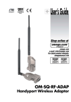
HPS-120
HandyPort-Serial
Wireless Solutions in your Hand
User’s Manual
UK / Europe / USA Office
Tel: +44 (0)8700 434040
Fax: +44 (0)8700 434045
E-mails - [email protected]
120-122 King Street ,Broughty Ferry,
Dundee, Scotland UK. DD5 1EW
Web Site: www.omniinstruments.co.uk
Australia / Asia Pacific Office
Tel +61 (0)894 888 960
Fax +61 (0)894 888 965
[email protected]
PO Box 105, Leederville
Western Australia, 6902
Table of Contents
1.
2.
INTRODUCTION ....................................................................................................................3
1.1.
FEATURES .........................................................................................................................3
1.2.
PACKAGE ..........................................................................................................................3
SPECIFICATIONS..................................................................................................................4
2.1.
GENERAL ..........................................................................................................................4
2.2.
RS-232 INTERFACE ...........................................................................................................5
2.2.1. Pin-out .........................................................................................................................5
2.2.2. Signals .........................................................................................................................5
2.3.
FACTORY SETTING .............................................................................................................5
2.4.
DISPLAY STATUS ................................................................................................................6
2.5.
RESET BUTTON .................................................................................................................6
2.5.1. Enter Configuration Mode............................................................................................6
2.5.2. Exit Configuration Mode ..............................................................................................6
2.5.3. Re-connection..............................................................................................................6
3.
3.1.
HARDWARE DESCRIPTION ..................................................................................................7
3.2.
POWER SUPPLY.................................................................................................................7
3.3.
INSTALL PROCEDURE .........................................................................................................7
4.
HARDWARE INSTALLATION ...............................................................................................7
USAGE ...................................................................................................................................8
4.1.
HYPER TERMINAL SETTINGS ..............................................................................................8
4.2.
CONFIGURATION ................................................................................................................8
4.2.1. Start Configuration.......................................................................................................8
4.2.2. Usage Printing .............................................................................................................8
4.2.3. After Configuration.......................................................................................................8
4.3.
COMMAND SET ..................................................................................................................9
4.3.1. Command List for Local Device...................................................................................9
4.3.2. Command List for Remote Device.............................................................................10
2
1. Introduction
Thank you for purchasing a HandyPort-Serial. The HandyPort-Serial can be used as a
component in many types of systems allowing them to communicate wirelessly with other
Bluetooth products such as PC-cards, laptops, handheld computers, mobile phones and other
HandyPort-Serial. The HandyPort-Serial is a suitable component in new products as well as in
existing products.
1.1. Features
z Supports Bluetooth Serial Port Profile and Generic Access Profile
z No need of external host and software
z Easy of installation and use
z Supports configuration of the local device
z Supports configuration of the remote device via Over-the-Air
z Easy of maintenance
z Supports up to 100 meter (Line of Sight)
z HPS-120 2 EA
z Antenna 2 EA
1.2. Package
z A USB Cable for Power Supply
z A Manual
3
2. Specifications
2.1. General
Baud Rate
Up to 115.2kbps (Recommend above 2.4kbps)
Supports 1.2/2.4/4.8/9.6/19.2/38.4/57.6/115.2kbps
Coverage
Up to 100 M
Connection
Point-to-Point
Signal
DCD, TxD, RxD, GND, CTS/DSR
RS-232 Interface
D_SUB 9 Pin Female
Standard
Bluetooth Specification Version 1.1
Frequency
2.400 ~ 2.4835GHz
Hopping
1,600/Sec, 1MHz Channel Space
Modulation
GFSK, 1Mbps, 0.5BT Gaussian
Tx. Power
Max 20 / Typical 16dBm (Class 1)
Rx. Sensitivity
-84dBm
Antenna Interface
SMA Female
Antenna Gain
Max. 2dBi
Power Supply
+5 ~ +12Vdc
Current
Max. 110mA
Operation
Size
Temperature
-20 ~ 75 °C
, DTR, RTS
Consumption
(Remark1)
35mm (W) x 65mm (D) x 16mm (H)
Remark1) The default hardware configuration is for using CTS. If you want to use DSR, please
contact us.
4
2.2. RS-232 Interface
2.2.1. Pin-out
2.2.2. Signals
Pin Number
Signal
Direction
Description
1
DCD
Output
Data Carrier Detect
2
TxD
Output
Transmitted Data
3
RxD
Input
Received Data
4
DSR
N/A (Input)
Option: Data Set Ready
5
GND
N/A
Signal Ground
6
DTR
Output
7
CTS
Input
8
RTS
Output
9
Vcc
(Remark1)
(Remark1)
Clear to Send
Request to Send
Input
Data Terminal Ready
Power Supply
Remark1) The default hardware configuration is for using CTS. If you want to use DSR, please
2.3. Factory Setting
The following is the factory setting of COM port.
z Baud rate: 9600 bps
z Data Bit: 8 bit
z Parity Bit: No parity
z Flow control: None
z Stop Bit: 1 stop bit
contact us.
5
2.4. Display Status
The following is status LED information.
z OPR (Red): When HPS-120 is powered on, it is turned on or flashing.
z LNK (Green): When a wireless link is on, it is turned on. If HPS-120 is in the
configuration mode, it will be flashing every second.
2.5. Reset Button
The RST button has the following functions.
z Enter / Exit the configuration mode
z Restore the factory settings
z Disconnect and reconnect a wireless connection.
2.5.1. Enter Configuration Mode
When the LNK LED is OFF, push the RST button. When the LNK LED is ON, you have to push
the RST button twice to enter the configuration mode. If you enter the configuration mode
successfully, LNK LED will be flashing every second. And HPS-120 COM port will be stored the
factory settings.
2.5.2. Exit Configuration Mode
You can have two options to exit the configuration mode.
Exit the configuration mode by software: Type “X”.
Exit the configuration mode by the RST button: Push the RST button.
2.5.3. Re-connection
When the LNK LED is on, you can push the RST button to disconnect and reconnect a wireless
link.
Waning!
If you push the RST button, the COM port of HPS-120 will be stored the factory setting.
6
3. Hardware Installation
3.1. Hardware Description
RST Button
Screw
RS-232
Connector
OPR LED
LNK LED
DC In Jack
Cable
USB
for Power
3.2. Power Supply
Connector
You can supply power to the HPS-120 as follows:
Antenna /
Use an AC/DC converter (Output Power: +5 ~ +12Vdc / 300mA).
th
You can supply power via 9 pin of D_SUB 9 Pin connector.
3.3. Install Procedure
Step 1: Assemble a provided antenna to HPS-120 body.
Step 3: Power on.
Step 2: Plug a HPS-120 into the COM port of device.
Use a provided USB cable.
Step 4: Configure the HPS-120, if necessary.
7
4. Usage
You can change the configuration of HPS-120 using Hyper Terminal.
4.1. Hyper Terminal Settings
Baud Rate: 9600 bps / Data Bit: 8 / Parity Bit: None / Stop Bit: 1 / Flow Control: None /
Emulation: VT100
4.2. Configuration
4.2.1. Start Configuration
Step 1: Plug a HPS-120 into a COM port of PC. And Power it on.
Step 2: Open a Hyper Terminal and set it up.
Step 3: Push the RST button on HPS-120. If you enter the configuration mode successfully,
LNK LED will be flashing every second.
Step 4: Hit the <Enter> key, 5 second later.
Step 5: Change the configuration of HPS-120 with commands, if necessary.
4.2.2. Usage Printing
If you are in the configuration mode, type “?” key. You will see the usage. All commands and
parameters are case sensitive. And you cannot use a <Backspace>.
4.2.3. After Configuration
After finishing the configuration, you have to execute a command “X” to apply changes.
8
4.3. Command Set
4.3.1. Command List for Local Device
Item
1.
Syntax
Connecting AAddr<Enter>
address
Description
Set
a
address
Remarks
remote
for
a
device A
3. COM port
BBaud Rate
CCOM Port
and
remote
wireless BD_ADDR always need to
connection.
be difference.
Change the baud rate
Baud Rate - 0: 1200, 1:
2. Baud rate
local
2400, 2: 4800, 3: 9600, 4:
19200, 5: 38400, 6: 57600,
7: 115200
This is only valid in connection
mode 2.
4. PIN code
EPIN<Enter>
Authentication Off: Type <Enter>
Paired
adapters
should
Authentication On: Type up to 11
have a same PIN code.
characters
5. Flow control
Connection Mmode
mode
0: None, 1: Hardware, 2:
Set the Flow control.
DTR/DSR, 3: Hardware &
DTR/DSR
6.
FFlow Control
Set a connection mode
0: 1:1 Mode, 1: WAIT Mode,
2:
REGISTER
and
CONNECT Mode
7. Friendly name
Nname<Enter>
Set a friendly name up to 11
characters.
8. Command for O
Enter configuration mode
the remote
for the remote.
Pparity
Set the parity bit.
0: None, 1: Odd 2: Even
10. Stop Bit
Sstop
Set the stop bit.
0: 1 Stop, 1: 2 Stop
11. View
V
Display
configuration
information
12. Exit
X
Apply changes.
13. Usage
?
Print the usage.
If you push the RST button, the COM port of HPS-120 will be stored the factory setting.
Waning!
9. Parity Bit
9
4.3.2. Command List for Remote Device
To change the configuration for a remote device via over-the-air, firstly you have to use a
command “O” at the local device. The following are a procedure for changing configuration of
remote device via over-the-air.
z Configure a remote device at the local device.
z Save changes at the local device.
z Make a connection between the local device and remote device (Automatically).
z Send changes from the local device to the remote device (Automatically).
z Apply changes at the remote device and reboot (Automatically).
Item
1.
Connecting
Syntax
Description
AAddr<Enter>
Set a connecting address for
address
2. Baud rate
Remarks
remote device.
BBaud Rate
Change the baud rate for the
remote.
3. COM port
CCOM Port
This is only valid in mode 2.
4. PIN code
EPIN<Enter>
Authentication Off: Type <Enter>
Paired adapters should
Authentication On: Type up to 11
have a same PIN code.
characters
FFlow Control
6.
MMode
Connection
mode
7. Friendly name
5. Flow control
Set the Flow control for remote.
Set a connection mode for
remote.
NName<Enter>
Set a friendly name up to 11
characters for remote.
8. Parity Bit
PParity
Set the parity bit.
0: None, 1: Odd 2: Even
9. Stop Bit
SStop
Set the stop bit.
0: 1 Stop, 1: 2 Stop
10 View
V
Display
information for remote
11. Exit
X
Save changes and return to
main menu.
12. Usage
?
configuration
Print the usage.
Remarks1: To configure a remote device via over-the-air, a local device must be able to make a
connection to the remote device.
Change a PIN for remote at the local -> Apply it. -> Change a PIN for local and apply it.
Remarks2: You can change a PIN code for the remote and local device as follows:
Remarks3: Once you change a connecting address, and connection mode for the remote, the
local device won’t be able to make a connection to the remote device.
10