1
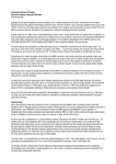
Product Specification & User Guide Document Number: DOC00298 Document Revision – C For pricing or any further information, please contact Omni Instruments Ltd. UK / Europe Office Tel: +44 845 9000 601 Fax: +44 845 9000 602 [email protected] www.omniinstruments.co.uk Australian Office Tel: +61 282 442 363 Fax: +61 294 751 278 [email protected] www.omniinstruments.com.au 888.668.8743 USA / Canada Office Tel: +1 866 849 3441 Fax: +1 866 625 8055 [email protected] www.omniinstruments.net Wireless IMU Product Specification & User Guide Document Number: Release / Revision Release / Revision Date: DOC00298 C October 14, 2014 Document Owner: Design Engineering Information provided in this document is believed to be accurate, however it is not guaranteed. MEMSense LLC reserves the right to change product specifications at anytime without notice. Document Number: DOC00298 Document Revision: C Product Number: MP00048 pg. i Document Change History Rev Status Description Date A Superseded New Document 8/29/2013 B Superseded Changed the magnetometer sensitivity. This new spec only applies to rev B or later product. 11/20/2013 C Released Corrected units on magnetometer noise density. 10/14/2014 Information provided in this document is believed to be accurate, however it is not guaranteed. MEMSense LLC reserves the right to change product specifications at anytime without notice. Document Number: DOC00298 Document Revision: C Product Number: MP00048 pg. ii TABLE OF CONTENTS 1.0 Introduction................................................................................................................................................... 1 2.0 Communications ........................................................................................................................................... 2 2.1 Bluetooth Communications .............................................................................................................. 2 2.2 Modes ............................................................................................................................................... 2 2.3 Sample Format .................................................................................................................................. 4 2.4 Measurements .................................................................................................................................. 5 3.0 Led Indication ................................................................................................................................................ 5 4.0 Mechanical .................................................................................................................................................... 6 4.1 Dimensions........................................................................................................................................ 6 4.2 Coordinate System ............................................................................................................................ 7 5.0 Electrical Specifications And Options ........................................................................................................ 8 5.1 Part Numbering ................................................................................................................................. 8 5.2 W2 Imu Accessories .......................................................................................................................... 8 5.3 Specifications .................................................................................................................................... 9 6.0 Terms, Conditions And Warranty ............................................................................................................. 10 Information provided in this document is believed to be accurate, however it is not guaranteed. MEMSense, LLC reserves the right to change product specifications at anytime without notice. Document Number: DOC00298 Document Revision: C Product Number: MP00048 pg. iii 1.0 Introduction The W2 IMU is the second generation Memsense wireless IMU that provides wireless serial digital outputs of triaxial acceleration, angular rate and magnetic field as well as temperature and barometric pressure via the Bluetooth™ wireless protocol. The inertial outputs are compensated over temperature for bias, scale factor, and cross-sensitivity. The accelerometers and gyroscope within the W2 IMU can be configured to different dynamic ranges over the wireless connection with a simple command structure. The available ranges for the gyroscopes are ±250, ±500, or ± 2000 °/sec and ±2g, ±4g, ±6g, ±8g, and ±16g for the accelerometers. With the Bluetooth™ capability, the IMU can communicate with a wide variety of hosts, such as PCs, tablets, phones, and embedded systems. The range of transmission can be affected by the environment, but typical range capabilities are on the order of 60 feet. An integrated rechargeable battery allows for up to 5 hours of power and can be charged via micro USB which makes the W2 IMU a convenient option for inertial measurement applications. The device measures 1.58" × 1.32" × 0.60" and can be either screw mounted or easily strapped down with the built-in strap bars. Multiple Wireless IMUs can be utilized simultaneously allowing inertial motion capture of multi-segmented objects common in human motion analysis. The miniature size, wireless multiple device connection and configurability of the W2 IMU makes it an exceptional sensor choice for applications such as human motion analysis, biomechanics, or animation. Figure 1 - Wireless IMU Functional Block Diagram Information provided in this document is believed to be accurate, however is not guaranteed. MEMSense LLC reserves the right to change product specifications at anytime without notice. Document Number: DOC00298 Document Revision: C Product Number: MP00048 pg.1 2.0 Communications 2.1 Bluetooth Communications The W2 IMU incorporates a wireless serial port module with a unique Bluetooth address. The address of each IMU is “W2IMU-<device SN> and can be found by a host system thru a discovery. Authentication with the W2 IMU requires a passkey with a PIN of “1234”. The serial port settings are shown in Table 1 Serial Port Settings. The IMU starts sending sample packets once a Bluetooth connection has been established with a host. Interference from other devices which use the same frequency range (2.4GHz) as Bluetooth such as 802.11 wireless networks can cause occasional packet loss. Other potential interference sources include “noisy” devices such as microwaves and fluorescent lights. Table 1 - Serial port settings PARAMETER SETTING Bits per second 115200 Data bits 8 Parity None Stop bits 1 Flow Control 2.2 No Modes The W2 IMU operates in two communications modes, data and configuration. The default communication mode is the Data Mode where the IMU outputs data described in the sample format section. The default settings for the W2 IMU are contained in Table 2. While operating in the Data Mode the IMU can be switched into the Configuration Mode by transmitting zzz/r via the wireless connection. Once the IMU is in the Configuration Mode, commands can be sent that configure the gyroscope and accelerometer dynamic ranges as well as the sample rate. Table 3 details the available configuration commands for the W2 IMU. A power reset clears changes not saved to the IMU and returns operation to the Data Mode. Table 2 - W2 IMU Default Settings SETTING Accelerometer Dynamic Range Gyroscope Dynamic Range Output Sample Rate DEFAULT VALUE 6 500 150 Information provided in this document is believed to be accurate, however is not guaranteed. MEMSense LLC reserves the right to change product specifications at anytime without notice. Document Number: DOC00298 Document Revision: C Product Number: MP00048 pg.2 Table 3 - Configuration Mode Commands COMMAND zzz\r i\r g<space> <Dynamic Range>\r a<space> <Dynamic Range>\r s<space> <Sample Rate>\r d\r x\r Note: “\r” denotes a carriage return. DESCRIPTION Enter Configuration Mode from Data Mode Request current settings information Change Gyroscope Dynamic Range to 250, 500, or 2000 Change Accelerometer Dynamic Range to 2, 4, 6, 8 or 16 Change output Sample Rate to 100, 125, or 150 Save current settings to Defaults. Exit Configuration Mode to Data Mode Gyroscope Default Dynamic Range Example A command sequence for changing the default gyroscope dynamic range to 2000 /s is provided below. STEP 1 2 3 4 COMMAND/INFO zzz\r g 2000\r Serial Number = 16274 Gyro Range = 2000 Accel Range = 6 Sample Rate = 150 d\r x\r DESCRIPTION Enter Configuration Mode Change Gyroscope Dynamic Range to 2000 IMU returns current settings Save the change to defaults. Exit Configuration Mode Accelerometer Default Dynamic Range Example A command sequence for changing the default accelerometer dynamic range to 16 g is provided below. STEP 1 2 3 4 COMMAND/INFO zzz\r a 16\r Serial Number = 16274 Gyro Range = 500 Accel Range = 16 Sample Rate = 150 d\r x\r DESCRIPTION Enter Configuration Mode Change Accelerometer Dynamic Range to 16 IMU returns current settings Save the change to defaults. Exit Configuration Mode Sample Rate Default Example A command sequence for changing the default sample rate to 100 Hz is provided below. STEP 1 2 3 4 COMMAND/INFO zzz\r s 100\r Serial Number = 16274 Gyro Range = 500 Accel Range = 6 Sample Rate = 100 d\r x\r DESCRIPTION Enter Configuration Mode Change Sample Rate to 100 IMU returns current settings Save the change to defaults. Exit Configuration Mode Information provided in this document is believed to be accurate, however is not guaranteed. MEMSense LLC reserves the right to change product specifications at anytime without notice. Document Number: DOC00298 Document Revision: C Product Number: MP00048 pg.3 2.3 Sample Format An individual data packet is collectively referred to as a sample. Data samples are formatted as shown in Table 4, Sample byte order format. Each data channel is represented by a signed 2’s complement, 2-byte short (16-bit) integer that represents the output level of the signal. To convert this value to its corresponding engineering unit see Section 2.4. Table 4 - Sample Byte Order Format BYTE 0 1 2 3 4 5 6 7 8 9 10 11 12 13 14 15 16 17 18 ELEMENT Synchronization byte (FF) Synchronization byte (FF) Synchronization byte (FF) Synchronization byte (FF) Message size (bytes) Product ID Message ID Sample Counter (MSB) Sample Counter (LSB) Gyro Range/Sample Rate Accelerometer Range Serial Number MSB Serial Number LSB Gyro X (MSB) Gyro X (LSB) Gyro Y (MSB) Gyro Y (LSB) Gyro Z (MSB) Gyro Z (LSB) BYTE 19 20 21 22 23 24 25 26 27 28 29 30 31 32 33 34 35 36 37 ELEMENT Accelerometer X (MSB) Accelerometer X (LSB) Accelerometer Y (MSB) Accelerometer Y (LSB) Accelerometer Z (MSB) Accelerometer Z (LSB) Magnetometer X (MSB) Magnetometer X (LSB) Magnetometer Y (MSB) Magnetometer Y (LSB) Magnetometer Z (MSB) Magnetometer Z (LSB) Temperature (MSB) Temperature (LSB) Reserved Pressure (MSB) Pressure Pressure (LSB) 8-bit Checksum All samples begin with four (4) synchronization bytes, where each byte contains 0xFF. The details on the structure of a sample are as follows (Note: all byte offsets are zero (0) based): BYTES 0-3 4 5 6 7-8 9 10 11 - 12 13 - 36 37 ELEMENT Synchronization bytes Message size Product ID Message ID Sample Counter Gyro Range/Sample Rate Accelerometer Range Serial Number Payload Checksum byte DESCRIPTION each byte encoded as 0xFF hex Size in bytes of entire data packet including complete header 3 for Wireless IMU Type of message. Data messages with MID = 0x14 hex (20 decimal). Represents a 16-bit counter of value of the number of samples with a rollover value of 65,535. Each count represents (sample rate)-1. Bits 7–4 identify gyro range: 0000 – 250 /s; 0001 – 500 /s; 0010 – 2000 /s Bits 3–0 identify sample rate: 0000 – 100Hz; 0001 – 125Hz; 0010 – 150Hz Bits 7–4 identify accel range: 0000 – 2 g; 0001 – 4g; 0010 – 8g; 0011 – 16 g Unique number identifying each device The payload size calculated as follows: payload size = message size – 13(header) – 1(Checksum byte) 8-bit checksum byte. Sum sample contents (header + payload). DO NOT include the checksum byte. The summed value should equal the checksum if the message is valid. If larger than 8-bit addition is used to calculate the checksum, the checksum will be the remainder of a divide by 256. Information provided in this document is believed to be accurate, however is not guaranteed. MEMSense LLC reserves the right to change product specifications at anytime without notice. Document Number: DOC00298 Document Revision: C Product Number: MP00048 pg.4 2.4 Measurements The gyroscope, accelerometer, and magnetometer values may be converted to rotational rate, acceleration, and gauss respectively. The data is transmitted as signed (2’s complement) 16-bit integers. The following function must be used for conversion of raw values: Equation 1: result = raw_payload digital sensitivity where the result is the converted value in the appropriate units (e.g. /s), “raw value” is the raw component-specific value from the payload (e.g. accelerometer X), and “digital sensitivity” is the digital sensitivity of the sensors configuration found in Table 7. Candidate ranges are as shown in Table 5, Sensor Dynamic Ranges. For example, a ±500 deg/s, ±6 G W2 IMU, the corresponding equations for the X component would be: X Gyro Value = Raw Payload Value 2.2888-2 X Accelerometer Value = Raw Payload Value 2.7466-4 where the “raw payload value” is taken from the sample payload corresponding to the x- components of the gyro and accelerometer, respectively. The resulting values have units of degrees/sec and gs, respectively. Table 5 – Sensor Dynamic Ranges Sensor Gyroscope Accelerometer Magnetometer Pressure Sensor Ranges ±250 /s ±500 /s ±2000 /s ±2 g ±4 g ±6 g ±8 g ±16 g ±4 gauss 260 – 1260 mbar Although the sensor data is temperature compensated, a customer’s application may require the use of temperature information, therefore a temperature measurement is provided. The temperature data provided requires a different conversion process. The data is transmitted as signed (2’s complement) 16bit integers. The following equation must be used for conversion of temperature sample values: Equation 2: Temperature Degrees C = Raw Payload Value x 1.8165 x10⁻² +25 where the result is the converted value in degrees Celsius and “raw value” is the raw value from the payload. The pressure sensor output is a 24 bit value and is located in bytes 33 – 35. The conversion of the raw output to millibar is accomplished using equation 3 below. Equation 3: Pressure mbar = RawPayloadValue⁄ 4096 Information provided in this document is believed to be accurate, however is not guaranteed. MEMSense LLC reserves the right to change product specifications at anytime without notice. Document Number: DOC00298 Document Revision: C Product Number: MP00048 pg.5 3.0 LED Indication The green LED on the IMU will indicate when the device is powered-on and when the Bluetooth connection has been established. When the IMU is powered-on and is not connected, the LED will blink slowly at a rate of approximately every 2 seconds. When a connection has been established, the blink cycle rate will increase to approximately once every second. A rapid 3 blink sequence followed by a 3 second off period indicates that the battery is low and should be charged. There is approximately 10 minutes of operation possible once the battery low indication is initiated. When the IMU is charging the inverse of the above described patterns will be indicated. 4.0 Mechanical 4.1 Dimensions The W2 IMU has four evenly spaced mounting holes that allow for the use of 4- 40, Socket Head Cap Screws. Two evenly spaced slots near the edges provide for mounting with a strap. Figure 2 - Physical dimensions (inches) Information provided in this document is believed to be accurate, however is not guaranteed. MEMSense LLC reserves the right to change product specifications at anytime without notice. Document Number: DOC00298 Document Revision: C Product Number: MP00048 pg.6 4.2 Coordinate System The coordinate system for the Wireless IMU follows the right hand rule convention. The sign convention for the accelerometers is configured to produce a positive signal when the Wireless IMU is accelerated in the opposite direction of the axis. As an example, with the Wireless IMU pictured in Figure 3 Wireless IMU Coordinate System, if the Z axis is pointed straight down towards the earth, it will produce 0 g for the X and Y axes and a positive 1 g for the Z-axis. A counterclockwise rotation of the IMU about any of the depicted axis will produce a positive angular rate output for the corresponding axis. Figure 3 - Wireless IMU coordinate system Information provided in this document is believed to be accurate, however is not guaranteed. MEMSense LLC reserves the right to change product specifications at anytime without notice. Document Number: DOC00298 Document Revision: C Product Number: MP00048 pg.7 5.0 Electrical Specifications and Options 5.1 Part Numbering Table 6 - Standard part number. Part W2-IMU 5.2 Accel. (g) ±2, ±4, ±6, ±8, and ±16 Rate (/s) ±250, ±500, and ±2000 W2 IMU Accessories The W2 IMU ships with a 3-foot micro USB cable used for charging and an ESD protective carrying case. The use of any Bluetooth transceiver is possible however the optimal range will be achieved with transceivers using non-chip based antennas. Information provided in this document is believed to be accurate, however is not guaranteed. MEMSense LLC reserves the right to change product specifications at anytime without notice. Document Number: DOC00298 Document Revision: C Product Number: MP00048 pg.8 5.3 Specifications Table 7 - W2 IMU Specifications PARAMETER SPECIFICATION Operational Requirements Charge Voltage Charge Current Charge Time Run Time Devices/Node Wireless Range Physical Properties Alignment Error Mass Acceleration Dynamic Range Bias (In Run) Offset Noise Density Digital Sensitivity Bandwidth UNITS 4.9 to 5.5 250 (300) 1.5 4.5 6 30 VDC mA hours hours Max m ±1 25 % grams 2 4 6 8 16 ±2 ±4 ±6 ±8 ±16 ±0.20 ±0.34 ±0.34 ±0.56 ±1.06 ±40 ± 40 ±40 ±40 ±40 0.2 (0.4) 0.3 (0.6) 0.5 (0.8) 0.6 (0.9) 1.6 (2.8) 9.1553 x 10⁻⁵ 1.8311 x 10⁻⁴ 2.7466 x 10⁻⁴ 3.6621 x 10⁻⁴ 7.3242 x 10⁻⁴ 50 50 50 50 50 CONDITIONS Typical, (IMU On) Typical Clear line of sight g mg mg mg/Hz-1/2 g/bit Hz Typical Maximum Typical (Max) -3dB point, Note 1 Angular Rate Dynamic Range 250 ± 250 500 ±500 2000 ± 2000 /s Bias (In Run) ±0.03 ±0.03 ±0.06 /s ±1.5 0.04 (0.07) ±1.5 0.04 (0.07) ±1.5 0.05 (0.09) /s Max /s/Hz-1/2 Typical (Max), 1 1.1444 x 10⁻² 50 2.2888 x 10⁻² 50 9.1553 x 10⁻² 50 /s/bit Hz -3dB point, Note 1 Offset Noise Density Digital Sensitivity Bandwidth Magnetic Field Dynamic Range Offset ±4 +/-0.05 Noise Density gauss gauss X and Y Axes 0.4 (0.8) Z Axis 0.5 (1.0) mgauss/Hz-1/2 Typical (Max), 1 Digital Sensitivity 1.8311 x 10⁻⁴ gauss/bit Temperature Digital Sensitivity 1.8165 x10⁻² ⁰C/bit Pressure Digital Sensitivity 2.44 x10⁻⁴ mBar/bit Absolute Max Ratings Acceleration Powered Charging Voltage Operating Temperature 2000 max -0.3 (min) +6.0 (max) 0 to +50 Storage Temperature -20 to +60 C 0 to +30 C Storage Temperature Typical Values at 25C and 0 /s unless otherwise noted g VDC Any axis 0.5ms C Long-Term Information provided in this document is believed to be accurate, however is not guaranteed. MEMSense LLC reserves the right to change product specifications at anytime without notice. Document Number: DOC00298 Document Revision: C Product Number: MP00048 pg.9 6.0 Terms, Conditions and Warranty DEFINITION : As used herein: “Seller” means MEMSense, 2693D Commerce Road, Rapid City, SD 57702. “Buyer” means the party purchasing Product(s) from the Seller. “Product” means all articles, materials, work or services offered by the Seller and described in the accompanying quotation, acknowledgement, invoice, or other Seller form. “Order” means any purchase Order or contract issued by the Buyer for Products provided by the Seller. WARRANTY : Seller warrants that the Products will be free from defects in material and workmanship and conform in all material respects to their applicable specifications for a period of one (1) year from the date of delivery (“Warranty Period”), when operated under normal conditions and in accordance with their applicable specifications. For any breach of this warranty, Seller will, at its option and expense and as its sole obligation, and as Buyer’s exclusive remedy, repair or replace any defective Product returned to Seller during the Warranty Period, provided that an examination by Seller discloses to Seller’s reasonable satisfaction that a defect is covered by this warranty. This warranty does not apply to any Products that have been (i) subject to misuse, neglect, or abuse, (ii) improperly installed or maintained, or (iii) repaired or altered by anyone other than Seller. The warranty period for Products repaired or replaced under this warranty shall be limited to the components repaired or replaced and shall run for a period of one hundred and eighty (180) days from the date of delivery or the balance of the original one (1) year Warranty Period (excluding the time the Products were out of service and in Seller’s plant), whichever is longer. EXCEPT AS STATED IN THIS SECTION, SELLER MAKES NO WARRANTIES, EXPRESS OR IMPLIED, AND SPECIFICALLY DISCLAIMS ANY IMPLIED WARRANTIES OF FITNESS FOR A PARTICULAR PURPOSE, MERCHANTABILITY, TITLE, AND NON-INFRINGEMENT OF THIRD PARTY RIGHTS. LIMITATION OF LIABILITIES - In no event shall Seller be liable to Buyer or any third party for consequential, indirect, punitive, special, or incidental damages (including but not limited to loss of profits) arising from or relating to the sale, delivery or use of the Products. Seller’s total cumulative liability under this Agreement to Buyer or any third party (including indemnity obligations), whether in contract or tort or otherwise, will not exceed the amount paid by Buyer to Seller for the Product sold hereunder giving rise to such liability. DELAYS - Seller shall not be liable for delay in delivery or for failure to manufacture, due to causes beyond its reasonable control, including but not limited to acts of God, acts of any government, acts of civil or military authority, acts of Buyer, application of US Government priorities, Government delays in granting Export Licenses, fires, strikes, floods, war, terrorism, riot or civil commotion, delays in transportation, difficulty in obtaining necessary labor or materials. In the event of any such delay, date of delivery shall be extended for a period of time equal to that lost by reason of the delay. TAXES - Prices do not include sales or excise tax, VAT, duties or other governmental charges resulting from this transaction or the manufacture, sale, ownership, possession, or use of the Products, all of which must be paid by Buyer. Buyer shall provide Seller a tax exemption certificate acceptable to the taxing authorities. SHIPMENT - Title to all purchased material and risk of loss therefore is passed from Seller to Buyer at the time of shipment from Seller’s facility. Unless otherwise agreed upon in writing, all purchased material will be shipped uninsured. Seller may request partial shipment and invoice therefore. EXPORT LICENSE – Buyer will comply with all applicable export and import control laws and regulations in its use of the Products and Buyer will not export or re-export the Products or any technical data or confidential information derived from or pertaining to the Products without all required United States and foreign government licenses. Information provided in this document is believed to be accurate, however is not guaranteed. MEMSense LLC reserves the right to change product specifications at anytime without notice. Document Number: DOC00298 Document Revision: C Product Number: MP00048 pg.10