1
ECM2 User Manual Rev. 1.5
7.8
Logic Structure
7.8.1 Combined AND/OR Logic Term
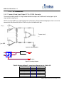
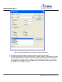
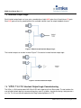
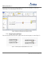
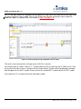
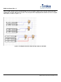
Relays can be connected to form various logic structures. The following example shows a combination of AND
and OR terms.
Figure 7-21 More complex logic structure
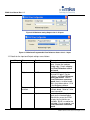
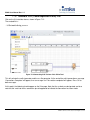
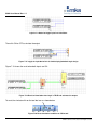
The logic term represented by this structure would be:
Out1 = (1 and 2 or 3 and 4) and 5 and 6 and (7 and 9 or 8 and 10)
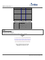
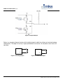
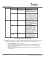
Figure 7-22 Equivalent logic gate for figure 14
Note
The logic above depicts the equivalent logic equation for
interlock logic condition, not the actual TTL gate level for timing
analysis purposes.
Page 105 of 121
© MKS Instruments CIT Products 2012, All rights reserved