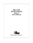
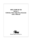
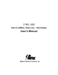
1
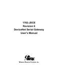
W5-JDB16 DeviceNet™ I/O Mux User’s Manual W estern Reserve Controls, Inc. Western Reserve Controls PUB 21.0 W5-JDB16 User’s Manual Although every effort has been made to insure the accuracy of this document, all information is subject to change without notice. WRC takes no liability for any errors in this document or for direct, indirect, incidental or consequential damage resulting from the use of this manual. Document PUB 21.0 Rev 1.00 July 2000 Copyright © 1999, 2000 WRC Western Reserve Controls, Inc. 1485 Exeter Road Akron OH 44306 330-733-6662 (Phone) 330-733-6663 (FAX) [email protected] (Email) http://www.wrcakron.com (Web) SmartMux, SmartMux-Lite and WRC are trademarks of Western Reserve Controls. DeviceNet is a trademark of the Open DeviceNet Vendor Association (“ODVA”). All other trademarks are property of their respective companies. Western Reserve Controls PUB 21.0 W5-JDB16 User’s Manual TABLE OF CONTENTS 1 OVERVIEW ............................................................................................................................................................................ 1 1.1 FEATURES............................................................................................................................................................................1 1.2 BASIC I/O OPERATION.......................................................................................................................................................2 1.2.1 Polled I/O ...................................................................................................................................................................... 3 1.2.2 Change-of-State (not implemented in Version 1.xx of the JDB16)..................................................................... 3 2 QUICK START....................................................................................................................................................................... 4 3 HARDWARE INSTALLATION AND CONFIGURATION............................................................................................ 7 3.1 OVERVIEW ...........................................................................................................................................................................7 3.2 LED OPERATION ................................................................................................................................................................7 3.3 DISCRETE I/O......................................................................................................................................................................8 3.4 A NALOG I/O.......................................................................................................................................................................9 3.5 POWER REQUIREMENTS..................................................................................................................................................10 3.5.1 Device power ..............................................................................................................................................................10 3.5.2 Output power ..............................................................................................................................................................11 3.6 SOFTWARE CONFIGURATION.........................................................................................................................................11 3.7 NETWORK CONFIGURATION ..........................................................................................................................................13 3.7.1 Network Termination ................................................................................................................................................13 1.1.1. DeviceNet Connection Wiring............................................................................................................................14 4 4.1 4.2 5 5.1 I/O ASSEMBLY FORMATS..............................................................................................................................................16 INPUT DATA .....................................................................................................................................................................16 OUTPUT DATA .................................................................................................................................................................16 GENERAL SPECIFICATIONS ..........................................................................................................................................17 I/O SPECIFICATIONS ........................................................................................................................................................19 6 ACCESSORIES AND OTHER WRC PRODUCTS .......................................................................................................21 7 TROUBLESHOOTING.......................................................................................................................................................22 LIST OF TABLES TABLE 2-1 BAUD RATE SELECTION ..............................................................................................................................................4 TABLE 2-2 A DDRESS SELECTION ...................................................................................................................................................5 TABLE 3-1 M ODULE STATUS LED (LABELED MS)...................................................................................................................8 TABLE 3-2 NETWORK STATUS LED (LABELED NS) .................................................................................................................8 TABLE 3-3 DISCRETE OUTPUT FIELD W IRING CONNECTIONS ................................................................................................9 TABLE 3-4 DISCRETE INPUT FIELD W IRING CONNECTIONS...................................................................................................9 TABLE 3-5 DISCRETE OUTPUT FIELD W IRING CONNECTIONS ..............................................................................................10 TABLE 3-6 POWER SELECTION OPTIONS ...................................................................................................................................10 TABLE 3-7 CONFIGURATION PARAMETERS..............................................................................................................................12 TABLE 3-8 NETWORK M AXIMUM LENGTHS............................................................................................................................13 i Western Reserve Controls PUB 21.0 W5-JDB16 User’s Manual TABLE 3-9 DEVICE NET W IRING TERMINATION .....................................................................................................................14 TABLE 3-10 DEVICE NET CONDUCTOR SIZES...........................................................................................................................15 LIST OF FIGURES FIGURE 1-1 W5-JDB16......................................................................................................................................................................1 FIGURE 3-1 W5-JDB16 OUTLINE DRAWING.................................................................................................................................7 FIGURE 3-2 DEVICE NET CABLE CONNECTOR.............................................................................................................................15 FIGURE 3-3 DEVICE NET CABLE SPECIFICATIONS....................................................................................................................15 TABLE 6-1 WRC REPLACEMENTS, SPARE PARTS AND OTHER PRODUCTS..........................................................................21 ii Western Reserve Controls PUB 21.0 W5-JDB16 User’s Manual PRELIMINARY 1 Overview The W5-JDB16 is a family of remote industrial I/O devices that multiplex discrete data acquisition and control signals in industrial or commercial applications. The W5-JDB16 is panel-mounted and supports serial communications on a DeviceNet link. The W5-JDB16 multiplexes eight (8) discrete input points, eight (8) discrete output points and four (4) 0-10V analog inputs onto a DeviceNet communications system. There are 3 versions of the W5-JDB16 available: W5-JDB16A W5-JDB16B W5-JDB16F 120Vac discrete I/O 24Vdc discrete I/O, 1 A outputs 24Vdc discrete I/O, 4 A outputs All devices operate in the same fashion. Except where specifically noted, discussions refer to all versions and the device will be referred to generically as a W5-JDB16 or simple JDB16. The W5-JDB16 multiplexer is designed as a Group 2 Only Server on the DeviceNet system and its I/O is read by and written to another device on the link defined as a DeviceNet Master (Client). W5-JDB16 supports the Predefined Master/Slave Explicit Message Connection, Polled I/O, Change-of-state I/O, Cyclic and Bit-Strobe. The device address and data rate are both switch selectable and software-configurable (using a third-party configuration tool). Each W5-JDB16 has 2 standard DeviceNet green/red LEDs - one for module status and one for network status. Section 3 of this document describes the installation of the W5-JDB16 multiplexer. WRC also provides numerous other DeviceNet I/O and DeviceNet bus extender products. Please refer to Section 6. Figure 1-1 W5-JDB16 1.1 Features General • DeviceNet compatible • ODVA Conformance tested to DeviceNet Spec 2.0 1 Western Reserve Controls PUB 21.0 W5-JDB16 User’s Manual • Defined as a DeviceNet Communications Device Profile 12 (0x0C) • Multiple I/O Message Data Options: Polled, (Cyclic, Change of State, Bit-Strobe – FUTURE) • Address and Baud Rate set with hardware switches or via software configuration • Panel mount • 2 standard DeviceNet module and network status LED’s • Pluggable 5-pin DeviceNet connection • Device powered from DeviceNet 11-25 Vdc network power or optional 24 Vdc auxiliary power • Isolated DeviceNet connection Discrete Inputs • 8 points – Vac or Vdc, depending upon model selected • 2500 V isolation • Isolation in groups of 4 • Input status LED indicator Discrete Outputs • 8 points – Vac or Vdc, depending upon model selected • Vdc outputs - 1 A bipolar or 4 A FET, depending upon model selected • 2500 V isolation • Each channel individually isolated • Each channel individually fused • Command output status LED indicator Analog Inputs • 4 analog input channels – 0-10 V • Software Configurable analog input resolution • Auxiliary 12 Vdc power output for external analog sensors • Selectable 8-bit or 10-bit resolution 1.2 Basic I/O Operation The W5-JDB16 operates as a combined discrete input and discrete output device on the DeviceNet network. It is a slave device which can be allocated by the system implementer to one specific master. There are several parameters that may be configured / modified by the user. These are collected in a block of data called the Parameter Object. (See Section 3.6.) They need not be modified and may be left as defaults, depending upon your application. The Polled I/O feature follows the “conventional” method of a master requesting data from and/or sending data to one slave at a time. This requires both a command message from the master and a response message from each slave for every set of I/O. To improve throughput on the network Change-of- 2 Western Reserve Controls PUB 21.0 W5-JDB16 User’s Manual State, Cyclic I/O and Bit-Strobe functions have been defined by the DeviceNet protocol. These functions are supported by WRC’s W5-JDB16 devices The discrete data returned to the master will contain both input and output point status data. 1.2.1 Polled I/O The master can poll (interrogate) the input and output statuses from the W5-JDB16, and it can energize/de-energize the discrete outputs at the W5-JDB16. The LEDs report the actual state of the input signals; i.e., they are lighted when the input to the circuit is energized and extinguished when the input signal is not present. Likewise, the output channel statuses and LED states indicate the commanded state (or control signal) of each output channel. Discrete outputs are energized by the master upon a poll command to the discrete output points. The LEDs report the commanded state of the output signals; i.e., they are lighted when commanded to energize (turn ON) and extinguished when commanded to turn OFF. If no data is sent to the JDB16 during a poll, then the outputs are put into the “idle” state and their actions are then governed by the Idle Action and Idle Value attributes of the Discrete Output Point objects. Both idle and fault operation are implemented for discrete outputs. The outputs can be set individually to hold last state or to implement user-defined states upon receipt of an “idle” command or upon a “fault” condition. You can implement these actions via the Parameter Object. Analog input data is reported in the bytes immediately following the discrete data byte. Each AI datum can be 1or 2 bytes long, depending upon your selection of resolution in Parameter 1. 1.2.2 Change-of-State (not implemented in Version 1.xx of the JDB16) A change-of-state (COS) message is an unsolicited message containing discrete input data sent by the W5-JDB16 to the host whenever any selected input changes ON-to-OFF or OFF-to-ON. You can individually select no, any or all inputs to cause a COS message. This selection is done by setting the Parameter 2 in the Parameter Object. When an appropriate COS occurs the entire input data (all eight input points) are transmitted to the master. Both acknowledged and unacknowledged COS messages are supported. By definition within the DeviceNet spec, a COS will also occur after a specified time interval if no inputs have changed state. 3 Western Reserve Controls PUB 21.0 W5-JDB16 User’s Manual 2 Quick Start To quickly and easily install your W5-JDB16 in your DeviceNet system, follow the instructions below. For more details, see Section 3. To Install and Establish DeviceNet Communications 1. Connect the DeviceNet cable to the 5-pin plug (supplied) according to DeviceNet cable wiring specifications. 2. Make sure that the DeviceNet network is terminated properly. (See Section 3.7 below.) 3. Set the baud rate and address of the JDB16 if different from default (see below). 4. Make sure that there is power on the DeviceNet network and that it is plugged into a Master device. 5. Plug the DeviceNet cable into the W5-JDB16. 6. The W5-JDB16 will undergo its initialization sequence, flashing both LEDs. After approximately 4 seconds, the Module Status LED (labeled “MS”) will go on solid green and network LED will flash green. 7. The green Network Status LED (labeled “NS”) will go on solid once the Master recognizes the unit on the link and allocates the connection. 8. The W5-JDB16 is now operating on the network. To Configure the Node Address and Baud Rate with the Switches 1. The address and baud rate can be set using the 8-position DIP switch block, SW1. 2. Switches 7 and 8 define the baud rate selection as follows: Table 2-1 Baud Rate Selection Baud Rate 125k 250k 500k SW S S S S DIP Switch Position 7 8 OFF OFF OFF ON ON OFF ON ON 7 OFF and S 8 OFF = 125k 7 ON and S 8 OFF = 250k 7 OFF and S 8 ON = 500k 7 ON and S 8 ON = Software settable baud rate and address (A switch in the OFF position represents a value of 0.) 3. Switches 1 through 6 define the address selection as follows: 4 Western Reserve Controls PUB 21.0 W5-JDB16 User’s Manual Table 2-2 Address Selection Node Address 0 1 2 3 4 5 … 62 63 1 2 32 OFF OFF OFF OFF OFF OFF 16 OFF OFF OFF OFF OFF OFF ON ON ON ON Switch Positions 3 4 Switch Position Values 8 4 OFF OFF OFF OFF OFF OFF OFF OFF OFF ON OFF ON ON ON ON ON 5 6 2 OFF OFF ON ON OFF OFF 1 OFF ON OFF ON OFF ON ON ON OFF ON (A switch in the OFF position represents a value of 0 and in the ON position represents a 1.) 4. Switch setting changes to NOT take effect until the devi ce is reset with either a RESET command or a power cycle. To Configure the Node Address and Baud Rate via Software 1. If switches 7 and 8 are ON, you can change the device address and/or the baud rate in software using your configuration tool or any command from the Master. (Defaults are 63 and 125k baud.) 2. If you change the device address via software, the W5-JDB16 will reset and assume the desired address after restart. 3. If you change the baud rate, the new baud rate will not become effective until the unit is power cycled or a Reset command is received from the Master. CAUTION: When using software to set the baud rate and address, the address indicated by DIP switches 1 – 6 may not reflect the device’s actual operating address at that time. This may be confusing to the user. To Read Discrete and Analog Input Data 1. Power down the JDB16. 2. Connect your discrete input signal cables to the 10 positions on the 20-pin connector plug so they line up with positions IN1 – IN8 on the INPUTS header connector, using one common line for each set of four input signals. 3. Connect your four 0-10 V analog input signals to the 8 positions on the 20-pin connector plug so they line up with position pairs COM-AINx on the INPUTS header connector. Plug the connector into the JDB16. 4. Reconnect the JDB16 and allocate a Poll Connection (Connection Instance 2) to the W5-JDB16 from the Master. 5. Perform a poll command to the W5-JDB16 from the Master. The discrete input channel values will be available in the first data byte returned, one bit per input signal. That, is input 1 is assigned to bit 0, input 2 is assigned to bit 1, etc. The analog input values will be in the next four bytes, starting with AI1. 5 Western Reserve Controls PUB 21.0 W5-JDB16 User’s Manual To Energize and De-energize Discrete Outputs 1. Power down the JDB16. 2. Connect your discrete output signal cables to the 16 positions on the 18-pin connector plug so they line up with positions 0x1-/0x+ on the OUTPUTS header connector. The “+” is used for the dc positive voltage or ac L1/L2 and the “-“ is used for the dc return or ac L2/L1. 3. Plug the connector into the JDB16. 4. Reconnect the JDB16 and allocate a Poll Connection (Connection Instance 2) to the W5-JDB16 from the Master. 5. Issue a Poll command from the Master with a data value of 00-FF hex. Each output will be turned ON or OFF, as defined by a corresponding bit value of 1 or 0. Output channel 1 is defined from bit 0, output 2 is defined from bit 1, etc. 6 Western Reserve Controls PUB 21.0 W5-JDB16 User’s Manual 3 Hardware Installation and Configuration 3.1 Overview The W5-JDB16 contains two LEDs to indicate the status of the device and the status of the network. The device can be connected to the main DeviceNet trunk line or to a drop line via screw terminations on the open, pluggable 5-pin DeviceNet connector supplied with your unit. Field wiring to the I/O circuits is also provided by screw terminations on pluggable 18- and 20-pole connectors. These are supplied with your unit. Figure 3-1 W5-JDB16 Outline Drawing 3.2 LED Operation A W5-JDB16 Multiplexer has two LEDs that provide visual status information to the user about the product and the DeviceNet network. See Table 3-1 and Table 3-2. 7 Western Reserve Controls PUB 21.0 W5-JDB16 User’s Manual Table 3-1 Module Status LED (labeled MS) LED State Module Status Meaning OFF No Power There is no power through DeviceNet. Green Device Operational W5-JDB16 is operating normally. Flashing Green Device in Standby W5-JDB16 needs commissioning. Flashing Red Minor Fault Recoverable fault. Red Unrecoverable Fault W5-JDB16 may need replaced. Flashing Red/Green Device Self-Testing W5-JDB16 is in self-test mode. Table 3-2 Network Status LED (labeled NS) LED State Module Status Meaning OFF No Power / Not on-line Flashing Green On-line, not connected Green On-line W5-JDB16 has no power or has not completed the Dup_MAC_ID test. W5-JDB16 is on-line but is not allocated to a Master. W5-JDB16 is operating normally. Flashing Red Connection time-out One or more I/O connections are timed out. Red Critical link failure W5-JDB16 has detected an error which makes it incapable of communicating on the link. (Bus off or Duplicate MAC ID). 3.3 Discrete I/O Each discrete I/O signal is isolated up to 2500 volts from the system electronics providing a high degree of reliability and performance in noisy or high EMI/RFI environments. The output signals are also point-to-point isolated and the input channels are isolated from each other in groups of 4. The field I/O is connected to the W5-JDB16 via pluggable (“quick disconnect”) connectors. The mating connectors are PCD ELFP18210 and ELFP20210. (Use this or equivalent component for spares or replacements.) This allows the user the convenience of wiring the I/O to the connector at a location remote to the actual W5-JDB16. It is also convenient during commissioning, maintenance and trouble-shooting of the field wiring. Table 3-3 and Table 3-4 define which terminations are used for each I/O channel. 8 Western Reserve Controls PUB 21.0 W5-JDB16 User’s Manual Table 3-3 Discrete Output Field Wiring Connections Channel No. Positive Terminal (dc) Negative Terminal (dc) 1 O1+ O1- 2 O2+ O2- 3 O3+ O3- 4 O4+ O4- 5 O5+ O5- 6 O6+ O6- 7 O7+ O7- 8 O8+ O8- Table 3-4 Discrete Input Field Wiring Connections Channel No. Positive Terminal (dc) Negative Terminal (dc) 1 IN1 1/4COM 2 IN2 1/4COM 3 IN3 1/4COM 4 IN4 1/4COM 5 IN5 5/8COM 6 IN6 5/8COM 7 IN7 5/8COM 8 IN8 5/8COM Important: All dc output circuits and dc input circuits are polarized. Proper operation requires that they be wired per the above chart. They will not work and the JDB16 may be damaged if the field wiring does not conform to the above chart. The pluggable wiring connector can accept I/O wire gage sizes 12 to 22 AWG. Each output channel is individually protected with a 4 Amp button fuse. 3.4 Analog I/O 9 Western Reserve Controls PUB 21.0 W5-JDB16 User’s Manual The analog I/O is connected to the W5-JDB16 via a pluggable (“quick disconnect”) connector. The mating connector is a PCD ELFP20210. (Use this or equivalent component for spares or replacements.) This allows the user the convenience of wiring the I/O to the connector at a location remote to the actual W5-JDB16. It is also convenient during commissioning, maintenance and trouble-shooting of the field wiring. Table 3-5 defines which terminations are used for each analog input. Table 3-5 Discrete Output Field Wiring Connections Channel No. Positive Terminal (dc) Negative Terminal (dc) 1 AIN1 COM 2 AIN2 COM 3 AIN3 COM 4 AIN4 COM The pluggable wiring connector can accept I/O wire gage sizes 12 to 22 AWG. Important: The analog input signals are not isolated from the system. Therefore, care must be taken in applying the signals to the JDB16. Important: The analog circuits are polarized. Proper operation requires that they be wired per the above chart. They will not work and the JDB16 may be damaged if the field wiring does not conform to the above chart. 3.5 Power Requirements 3.5.1 Device power The W5-JDB16 can be powered either from the DeviceNet connection power supply or from an external 24 Vdc power supply. The selection is made using a jumper on the 3-pole stake jumper labeled POWER. In the DNET position, the W5-JDB16 is powered from the 11-25 Vdc provided by the DeviceNet network. In the AUX position, the JDB16 is power from a user-supplier dc source connected at terminals 1 and 2 (labeled +24V and COM) on the OUTPUTS terminal block. The W5-JDB16 consumes 45 mA of current at 24 Vdc, or 1.1 Watts, typical. Table 3-6 Power Selection Options Power source Voltage POWER Jumper Connections DeviceNet 11-25 Vdc E1-E3 DeviceNet cable V+ and V- External PS 11-25 Vdc E1-E2 OUTPUTS terminal block +24V and COM Fuse 1AMP next to DNet connector 1AMP next to OUTPUTS connector Using the external power source reduces the load on the DeviceNet power supply and provides a degree of electrical isolation between the JDB16 and the network. 10 Western Reserve Controls PUB 21.0 W5-JDB16 User’s Manual Power to and from the field actuators and sensors connected to the I/O circuits is supplied by the user from the field wiring. No other external power supply is required to operate the W5-JDB16. 3.5.2 Output power The JDB16 provides a convenient +12 Vdc power supply that may be used to energize analog sensors. It can source up to 15O mA and is provided at terminals 1 and 2 (COM and +12V) on the INPUTS connector. 3.6 Software Configuration A W5-JDB16 Multiplexer is software-configured for several parameters. The Table 3-7 below defines the legal values and the default values for the device address (referred to as the device’s MacID), baud rate and I/O configuration selections available. 11 Western Reserve Controls PUB 21.0 W5-JDB16 User’s Manual Table 3-7 Configuration Parameters Param. Instance Parameter Parameter Choices Default Setting Default Value Definition / Comments 0 8-bit contained in 1 byte; 10bit contained in 2 bytes 4 Adjusting this value changes the poll response size. 0x00 Each DO defined independently. 1 bit per DO. Bit 0 = DO 1; Bit 7 = DO 8. 0 Each DO defined independently. 1 bit per DO. Bit 0 = DO 1; Bit 7 = DO 8. 0 Each DO defined independently. 1 bit per DO. Bit 0 = DO 1; Bit 7 = DO 8. 0 Each DO defined independently. 1 bit per DO. Bit 0 = DO 1; Bit 7 = DO 8. 0 = 8-bit Analog Data Resolution 1 8-bit 1 = 10-bit Number of Analog Inputs 2 0 – 4 AI’s 4 0 = Fault Value 1 = Hold Last State Output Fault Action 3 Fault Value (for each bit) Range = 0x00 – 0xFF 0 = OFF 1 = ON Output Fault Value 4 Turn OFF (for each bit) Range = 0x00 – 0xFF 0 = Idle Value 1 = Hold Last State Output Idle Action 5 Idle Value (for each bit) Range = 0x00 – 0xFF 0 = OFF 1 = ON Output Idle Value 6 Turn OFF (for each bit) Range = 0x00 – 0xFF Definitions of these parameters are as follows: 1. Analog Data Resolution: The JDB16 can report the analog inputs with either 8-bit resolution or 10-bit resolution. 8 bits can be represented in 1 byte of data and provides 1 in 12 Western Reserve Controls PUB 21.0 2. 3. 4. 5. 6. W5-JDB16 User’s Manual 256, or 0.39%, resolution, which is 39 mV. 10 bits require 2 data bytes and provides 1 in 1024, or 0.10%, resolution, which is 10 mV. Number of Analog Signals: Your pole response size can be optimized to reduce bandwidth on the DeviceNet link if you are using less than all 4 analog channels, or none at all. Each implemented analog channel requires 1 or 2 bytes of data, as described above. Output Fault Action: Selection to determine whether each output will hold its last state or assume the value identified in the next parameter upon a device fault, 1 bit per channel. Output Fault Value: The value each output will assume after a Fault if Fault Value is selected above (hold last state is not selected), 1 bit per channel. Output Idle Action: Selection to determine whether each output will hold its last state or assume the value identified in the next parameter if an Idle Command is issued by the Master, 1 bit per channel. Output Idle Value: The value each output will assume upon an Idle Command if Idle Value is selected above (hold last state is not selected), 1 bit per channel. 3.7 Network Configuration DeviceNet specifications provide for a maximum network distances for the main trunk line and drop lines, depending upon the baud rate used on the network. They are: Table 3-8 Network Maximum Lengths Trunk Line Length Drop Length Maximum Distance Maximum Cumulative Baud Rate Meters Feet Meters Feet Meters Feet 125k baud 5OO m 164O ft 6m 2O ft 156 m 512 ft. 25Ok baud 25O m 82O ft 6m 2O ft 78 m 256 ft. 5OOk baud 1OO m 328 ft 6m 2O ft 39 m 128 ft. 3.7.1 Network Termination A DeviceNet system must be terminated at each end of the trunk line. The host controller and the last W5-JDB16 or other DeviceNet device on the network must always be terminated to eliminate reflections, even if only two nodes are present. The DeviceNet specifications for the terminating resistor are: • 121 ohm • 1% metal film • 1/4 Watt An appropriate terminating resistor kit, WRC part number RM121DN, is included with your W5JDB16. Important: Per the DeviceNet spec -- do not terminate devices on drop lines. 13 Western Reserve Controls PUB 21.0 W5-JDB16 User’s Manual 1.1.1. DeviceNet Connection Wiring The supplied DeviceNet connection plug accepts cable sizes from 12 AWG - 24 AWG. The maximum wire size (12 AWG) has an area of 653O circular mils and the smallest (24 AWG) has an area of 3265 circular mils. Where not prohibited by local government or wiring regulations or company policy, multiple wires can be inserted each connection point on the plug as long as the total wire area does not exceed that of a 12 AWG wire. Use the chart below as a guide. Phoenix Contact recommends using the same size wires be used when connecting more than one wire in a screw termination. UL may require the use of crimped ferrules to connect multiple wires together. Table 3-9 DeviceNet Wiring Termination Wire AWG Wire area (circular mils) Maximum Wires per Terminal 12 653O 1 14 411O 1 15 3265 2 16 258O 2 18 162O 4* 2O 1O22 6* 22 645 9* 24 4O4 16 * * WRC does not recommend using more than 2 wires in any wire terminal. The conductor sizes for DeviceNet cables are: 14 Western Reserve Controls PUB 21.0 W5-JDB16 User’s Manual Table 3-10 DeviceNet Conductor Sizes Function Thick Wire Thin Wire Power 15 AWG 22 AWG Signal 18 AWG 24 AWG Figure 3-2 DeviceNet cable connector Figure 3-3 DeviceNet cable specifications 15 Western Reserve Controls PUB 21.0 W5-JDB16 User’s Manual 4 I/O Assembly Formats The following tables define the format of the data bytes sent to and received from the JDB16. 4.1 Input Data The format of the input data is defined by the resolution of the analog input signal, as defined in Parameter 1. For 8-bit resolution Instance 1 is used; for 10-bit resolution Instance 3 is used. JDB16 Input Assembly Data Attribute Format - Instance 1 (default) Byte 0 1 2 3 4 Bit 7 Input 8 Bit 6 Input 7 Bit 5 Input 6 Bit 4 Bit 3 Input 5 Input 4 Analog Input Point 1 Analog Input Point 2 Analog Input Point 3 Analog Input Point 4 Bit 2 Input 3 Bit 1 Input 2 Bit 0 Input 1 Bit 1 Input 2 Bit 0 Input 1 AI1,MSB AI1, bit8 AI2,MSB AI2, bit8 AI3,MSB AI3, bit8 AI4,MSB AI4, bit8 JDB16 Input Assembly Data Attribute Format - Instance 3 Byte 0 1 2 3 4 5 6 7 8 Bit 7 Input 8 Bit 6 Input 7 Bit 5 Bit 4 Bit 3 Input 6 Input 5 Input 4 Analog Input Point 1, bits 0 0 Analog Input Point 2, bits 0 0 Analog Input Point 3, bits 0 0 Analog Input Point 4, bits 0 0 Bit 2 Input 3 –7 –7 –7 –7 4.2 Output Data JDB16 Object Assembly Instance Data Format (Instance 2) Byte 0 Bit 7 Output 8 Bit 6 Output 7 Bit 5 Output 6 Bit 4 Output 5 16 Bit 3 Output 4 Bit 2 Output 3 Bit 1 Output 2 Bit 0 Output 1 Western Reserve Controls PUB 21.0 W5-JDB16 User’s Manual PRELIMINARY 5 General Specifications Product: W5-JDB16 – DeviceNet 16-Point Discrete I/O with Analog Multiplexer Description: Remote multiplexer, compatible with ODVA’s DeviceNet protocol for discrete I/O. This is a product family which supports eight (8) discrete inputs, eight (8) discrete outputs and four (4) analog inputs. The family members include: § W5-JDB16A – 120Vac discrete I/O, 0-10V analog input § W5-JDB16B – 24Vdc discrete I/O, 0-10V analog input § W5-JDB16F – 24Vdc high-power discrete I/O, 0-10V analog input Device Profile: General Purpose Discrete I/O, Class 07, with objects: - Identity (Class 01 hex) - Message Router (Class 02 hex) - DeviceNet (Class 03 hex) - Assembly (Class 04 hex) – 3 instances - Connection (Class 05 hex) - Discrete Input (Class 08 hex) – 8 instances - Discrete Output (Class 09 hex) – 8 instances - Analog Input (Class 0A hex) – 4 instances - Parameter (Class 0F hex) – 6 instances DeviceNet Conformance: Designed to conform to the ODVA DeviceNet Specification Volume I, Version 2.0 and Volume II, Version 2.0. Communications: Predefined Master/Slave Connection Set, Group 2 Only Server DeviceNet I/O Protocols: Poll (Change-of-state (COS), Cyclic – future) Baud rate: 125k, 250, 500k - switch selectable or software selectable (default = 125k) DIP Switch: Switches 7 and 8 on 8-position DIP switch S7 OFF & S8 OFF = 125K S7 ON & S8 OFF = 250K S7 OFF & S8 ON = 500K S7 ON & S8 ON = SOFTWARE SETTABLE BAUD AND ADDRESS Address selection: Address number 1 to 63, switch selectable or software selectable (default = 63) Switches 1 – 6 on 8-position DIP switch All switches OFF: address = 0 All switches ON: address = 63 S7 ON & S8 ON = SOFTWARE SETTABLE BAUD AND ADDRESS DeviceNet Connection: W5-JDB16: 5-pin pluggable header (male) Phoenix Contact MSTBA 2.5/5-G-5.08/AU DeviceNet Cable: 5-contact plug (female contacts) – color-coded Phoenix Contact MSTB 2.5/5-ST-5.08/AU (not included, user supplied) Network Termination: None required Status Indicators: Module Status: green/red bi-color LED 17 Western Reserve Controls PUB 21.0 W5-JDB16 User’s Manual Network Status: green/red bi-color LED Voltage Isolation: 2500V for each output circuit, 2500V for each group of 4 Input Circuits Maximum power: 200 mA @ 11 Vdc - 90 mA @ 25V dc unregulated power supply, not including Output loads (power provided by the DeviceNet network, or Auxiliary 24VDC power) Discrete Inputs: 8 discrete isolated inputs, 2 groups of 4, each group with one common Discrete Outputs: 8 discrete outputs, isolated channel-to-channel and channel-to-system 2 amp AC (A), 1 amp DC (B), 4 amp DC (F) max per output Analog I/O: 4, 0-10 volt inputs with individual common terminals, all same common (4 terminals) I/O Refresh Rate: Discrete I/O: 400 us for all points (2.5 kHz) Analog I/O: 400 us per input (2.5 kHz for 1 point, 625 Hz for 4 points) Aux Power Output: +12 VDC+/-5%, @ 150 mA I/O Wiring: discrete outputs: 16 positions on an 18-pole open, header connector: Phoenix MSTBA 2.5/18G-5.08 or equivalent Mates to pluggable connector MSTB 2.5/18-ST-5.08 or equivalent (included) I/O wire size: 12 - 24 AWG discrete inputs: 10 positions on a 20-pole on-board header connector Phoenix MSTBA 2.5/20G-5.08 or equivalent Connectors labeled on PCB Mates to pluggable connector: MSTB 2.5/20-ST-5.08 or equivalent (included) I/O wire size: 12 - 24 AWG analog inputs: 8 positions on a 20-pole on-board header connector Phoenix MSTB 2.5/20-G5.08 or equivalent I/O wire size: 12 - 24 AWG I/O Fuses: One 1A (B version) or 4A (A & F versions), 250V button fuse per output I/O LEDs: 16, one LED per each discrete input and output point – LED defines microprocessor status of input or output Mounting: Panel mount 4.1” x 6.6” mounting hole dimensions 4/40 mounting hole with 0.75” diameter clear space Size: 4.5” x 7.0” overall dimensions with 0.188” clear space on 4.5” dimension Operating Temp: 0-60 ºC Humidity: 0-95% RH, non-condensing Agency Approvals: UL listed (pending), CE (pending) 18 Western Reserve Controls PUB 21.0 W5-JDB16 User’s Manual 5.1 I/O Specifications Ratings Min Typical Max Units Comments Power (DeviceNet) 11 24 25 Vdc per DeviceNet spec Power (aux input) 11 24 27 Vdc Power (aux output)* 11.4 12 12.6 Vdc *Vin>Vout +1V 120 5 140 6 25 30 Vac mA rms ms ms Vrms each channel plus DNet communication time plus DNet communication time Between groups & DNet common 24 10 50 21 8 25 30 Vdc mA Vdc ms ms Vrms each channel each channel plus DNet communication time plus DNet communication time Between groups & DNet Common 120 140 2.0 400 2.5 100 200 10 10 Vdc A V mA A rms V/µs ms ms Vrms 60 1.0 60 1.0 5 10 10 Vdc A V mA A peak ms ms Vrms 48 4.0 50 0.01 10 1 1 Vdc A V mA A peak ms ms Vrms +10 Vdc Discrete inputs – W5-JDB16A On voltage 90 Input On current 3 Turn-on time Turn-off time Isolation 2500 Discrete inputs – W5-JDB16B, F On voltage 15 Input On current 6 Off voltage Turn-on time Turn-off time Isolation 2500 Discrete outputs – W5-JDB16A Line voltage 12 Output current 0.05 Peak off-state voltage Off-state leakage Surge current Static dv/dt Turn-on time Turn-off time Isolation 2500 Discrete outputs – W5-JDB16B Line voltage 3 Output current 0.01 Peak off-state voltage Off-state leakage Surge current Turn-on time Turn-off time Isolation 2500 Discrete outputs – W5-JDB16F Line voltage 0 Output current 0.0 Peak off-state voltage Off-state leakage Surge current Turn-on time Turn-off time Isolation 2500 Analog input Operating input voltage 0 24 0.1 24 19 10 A total, all channels @120Vac 1 cycle plus DNet communication time plus DNet communication time Between outputs & DNet Common 7.5 A @ 25 oC total, all channels plus DNet communication time plus DNet communication time Between groups & DNet Common all channels simultaneously plus DNet communication time plus DNet communication time Between groups & DNet Common Western Reserve Controls PUB 21.0 Max input voltage Resolution Isolation W5-JDB16 User’s Manual +20 0.1 0 20 Vdc % full scale (10-bits) Vrms Between AIs & DNet Common Western Reserve Controls PUB 21.0 W5-JDB16 User’s Manual 6 Accessories and Other WRC Products The following components can be used with a JDB16x for replacements or spare parts, or as complementary devices as a part of your DeviceNet system. Table 6-1 WRC Replacements, Spare Parts and Other Products Part WRC Part Number DIN rail WRC 50022 Terminating resistor, axial lead RM121DN Terminal block connector plug, 18-position KPELFP18210 Terminal block connector plug, 20-position KPELFP20210 Discrete I/O block – 4 channels 1782-JDB4 Discrete I/O block – 8 channels 1781-JDB8 Analog Input block – 4 channels, 10-bit 1782-JDA4 Analog I/O block – 8 channels, 12-bit 1782-JDA8 DeviceNet to Serial I/O Gateway 1782-JDC DeviceNet to Modbus Gateway 1782-JDM Discrete I/O block – 24 channels WRC1-JDB24 Discrete I/O block – 48 channels WRC1-JDB48 Discrete I/O, Analog Input block – 24 DIO, 32 AI WRC1-JDA/24 Discrete I/O, Analog Input block – 48 DIO, 32 AI WRC1-JDA/48 Analog I/O block - 32 channels WRC1-JDAIO Discrete and Analog I/O block – 24 DIO, 32 AIO WRC1-JDAIO/24 Discrete and Analog I/O block – 48IO, 32 AIO WRC1-JDAIO/48 Discrete I/O block – 8 DIs, 8 DOs, 4 AIs W5-JDB16x DeviceNet, CANopen Extender, DIN mount WRC-CANX-DIN-DN SDS Extender, DIN mount WRC-CANX-DIN-SD DeviceNet, CANopen Extender, DIN mount WRC-CANX-DIN-C7 DeviceNet, CANopen Extender, NEMA box WRC-CANX-NEM-AU DeviceNet, CANopen Extender, NEMA box WRC-CANX-NEM-DN SDS Extender, NEMA box WRC-CANX-NEM-SD DeviceNet, CANopen Extender, Fiber Optic, NEMA box WRC-CANR-DF-DN 21 Western Reserve Controls PUB 21.0 W5-JDB16 User’s Manual 7 Troubleshooting This section identifies some of the common problem observed when commissioning or operating a DeviceNet and W5-JDB16. Problem: Module Status LED is solid Green Network Status LED is flashing Green Device will not communicate on the network Possible Solutions: 1. Network does not have a terminating resistor. Add a 121 ohm resistor across the CAN_H and CAN_L signals at the first and last nodes. Problem: Module Status LED is solid Red Network Status LED is flashing Green or solid Green Device will not perform I/O Possible Solutions: 1. One or more channels were configured as Discrete Outputs and an input module with an active input signal is located in one or more of those channel positions. Problem: An output device does not turn on when commanded. Module LED is OFF. Possible Solutions: 1. An output module is not plugged into the channel selected. 2. The selected channel was not configured as an output. 3. The unit is damaged. Problem: An output device does not turn on when commanded. Module LED is ON. Possible Solutions: 1. The fuse is blown. 2. There is a loose connection in the field wiring. 3. The field wiring is not properly connected from hot to the module to the actuator to common. 4. If it is a dc module, the wiring to the module is the wrong polarity. 5. The module is damaged. 22