1
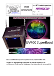
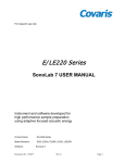
W CS™ W ater Conditioning System
USER MANUAL
A system developed for maintaining bath water quality in Covaris
AFA™ instrumentation
Product Name:
Water Conditioning System
Product Number:
WCS
UNIVERSAL PRECAUTIONS
Universal Precautions should be followed on all specimen samples, regardless of whether a sample is known to
contain an infectious agent. Laboratories handling specimen samples are advised to comply with applicable parts of
the following governmental and clinical standards, or their equivalent in the country of use:
•
Centers for Disease Control (CDC), Universal Precautions for Prevention of Transmission of HIV and Other
Bloodborne Infections, published 1987, updated 1996
•
Clinical and Laboratory Standards Institute (CLSI), GP17-A2 Clinical Laboratory Safety; Approved
Guideline - Second Edition, published 2004, ISBN 1-56238-530-5
•
Clinical and Laboratory Standards Institute (CLSI), M29-A3 Protection of Laboratory Workers from
Occupationally Acquired Infections; Approved Guideline, Third Edition, published 2005, ISBN 1-562385674
•
Occupational Safety and Health Administration (OSHA), 29 CFR 1910.1030 Bloodborne Pathogens
•
International Standards Organization (ISO) 15190:2003, Medical Laboratories – Requirements for Safety
Trademarks
Patented or patent pending and registered or registration-pending trademarks of Covaris are protected.
Registered names and trademarks used in this document, even when not specifically marked as such, are not to be
considered unprotected by law.
WCS and AFA are either registered trademarks or trademarks of Covaris, Inc. in the United States and/or other
countries.
Clorox is a registered trademark of The Clorox Company.
Information subject to change without notice
For Research Use Only
Not for use in diagnostic procedures
Publication P/N 010100 Rev C
May 2011
Products covered by Patent No. US6, 719,449, US6, 948,843, and other pending applications
Copyright ©2011 Covaris, all rights reserved.
Covaris, Incorporated
14 Gill St, Unit H
Woburn, Massachusetts
01801-1721 USA
WCS User Manual
Printed in U.S.A.
2
Warranty
When used in accordance with written instruction and under normal operating conditions, the Covaris
instruments are guaranteed to be free of defects in MATERIAL and WORKMANSHIP for one (1) year from
the date of original delivery. Any component which proves defective during the stated period will be repaired
free of charge or replaced at the sole discretion of Covaris, F.O.B., Woburn, Massachusetts, provided the
defective component is returned properly packaged with all transportation charges prepaid. The customer is
expected to perform basic diagnostics and component replacement with telephone support from Covaris
personnel. If Covaris personnel are required to perform on-site repair, all travel costs are paid by the
customer. A limited warranty as specified may apply to certain components of the equipment.
Warranty Exceptions
This warranty is void if failure of the software or hardware has resulted from accidents, abuse, improper
maintenance, or repair, or misapplication by the customer. It is also void if damage is caused by any
unauthorized attachments or if modifications are made to the equipment. Removing or tampering with the
Safety Enclosure will void the warranty, and the customer will assume all liabilities.
This warranty is limited to the original purchaser and is not transferable.
CONTACT COVARIS, INC. SHOULD YOU HAVE ANY QUESTIONS CONCERNING THIS EQUIPMENT.
Warranty Services
The purchased equipment is covered by a twelve (12) month warranty which includes all the service and
support necessary so that the customer can operate the equipment successfully. Extended warranties are
available at the end of the original 12 month warranty period.
Services included with the original purchase of the system are:
Installation and Training – Setup and installation of the equipment and operator training can be purchased
at time of initial acquisition of the equipment. Both will be performed by a qualified Covaris service
representative. One half day will be scheduled to perform the installation and on-site training.
•
The operators’ training will include valuable hands-on time with the equipment.
•
Preventative maintenance and troubleshooting tips will also be covered.
Technical Support – On-going assistance with the operation or application of the equipment and/or
troubleshooting is provided via:
•
Telephone (+1 781 932 3959) during the hours of 9:00am to 4:00pm, Monday through Friday,
o
o
•
United States, Eastern Standard Time (EST).
Greenwich Mean Time (GMT-05:00)
E-mail queries to [email protected]
Parts Replacement – Replacement of parts (excluding consumables) for normal operation of equipment are
provided on a priority basis. Shipping charges are included. Failure due to accident, abuse, or improper
operation is not covered.
WCS User Manual
3
This page intentionally left blank.
WCS User Manual
4
TABLE OF CONTENTS
INTRODUCTION.............................................................................................................................. 6
1.0
1.1
Overview of the Manual ............................................................................................................... 6
1.2
Safety Symbols and Warnings..................................................................................................... 6
1.3
For the safety of operating personnel .......................................................................................... 7
1.4
To prevent damage to the equipment:......................................................................................... 7
1.5
Acronyms employed in this User Manual .................................................................................... 7
1.6
Product Description ..................................................................................................................... 8
2.0
System Installation and Setup ...................................................................................................... 9
3.0
Indicators and Controls ............................................................................................................... 12
4.0
System Operation ........................................................................................................................ 13
5.0
Optional Laptop Computer Tray ................................................................................................. 14
6.0
Cleaning ........................................................................................................................................ 15
7.0
Specifications ............................................................................................................................... 15
8.0
Service .......................................................................................................................................... 16
Appendix A – Periodic Maintenance ....................................................................................................... 17
Appendix B – User Guidelines and Troubleshooting .............................................................................. 22
Appendix C – Bio-safety References ...................................................................................................... 23
WCS User Manual
5
1.0
INTRODUCTION
1.1
Overview of the Manual
This manual contains operation and service instructions for the Covaris WCS™ Water
Conditioning System. It contains background information essential to the proper use and care of
this equipment.
Should any unforeseen problems occur with the normal operation of the equipment, contact
Covaris Technical Support immediately.
The following definitions apply in this manual:
1.2
NOTE:
Inconvenience if disregarded.
CAUTION:
Equipment damage may occur.
WARNING:
Personal injury may occur.
Safety Symbols and Warnings
The following symbols are employed in product labeling and in this manual. Where these relate to
safety risks, failure to observe the associated precautions could result in injury to people or
damage to property.
This is the general alert symbol. It may be used to alert you to potential safety hazards. Obey all
safety messages that follow this symbol.
This symbol is used to identify an ELECTRICAL SHOCK hazard.
This symbol is used to identify an ULTRAVIOLET LIGHT hazard.
This symbol is used to identify a potential BIOLOGICAL hazard.
WCS User Manual
6
1.3
For the safety of operating personnel
1. Make sure that the power supply module is properly grounded. Employ a power cable
with a grounding prong, plugged to a power receptacle with a grounded receptacle. DO
NOT operate the unit if it is not properly grounded.
2. The unit is equipped with a power plug appropriate for the destination country. DO NOT,
under any circumstances, remove the grounding prong from the power cord.
3. Always disconnect power to the equipment (unplug) before performing any service or
maintenance. Reconnect power only as instructed.
4. Employ only the 12 volt DC power module provided with the unit, or a replacement
provided by Covaris.
5. Follow all precautions when changing the UV lamp. Avoid exposure to direct or strongly
reflected germicidal ultraviolet rays. Germicidal ultraviolet rays are harmful to the eyes
and skin.
6. THE ULTRAVIOLET LAMP CONTAINS MERCURY (Hg). Handle carefully to avoid
breaking the lamp. Dispose of used lamps according to disposal laws. For further
information, see one of the following websites or contact Covaris.
www.lamprecycle.org (North America)
www.lamprecycling.com (North America)
www.mercuryrecycling.co.uk (UK)
www.malampe.org (France)
7. If there is a safety related malfunction, DO NOT operate the equipment and contact
Covaris immediately.
8. If the equipment is used in a manner not specified by the manufacturer, the protection
provided by the equipment may be impaired. Do not remove safety labeling.
1.4
To prevent damage to the equipment:
1. The WCS is designed for indoor use and to operate in typical ambient laboratory
conditions e.g., 15 to 32°C (60 to 90°F). DO NOT operate the instrument in a cold room
environment. The system is designed to operate with a water bath and re-circulating
heater/chiller apparatus to control sample temperature.
2. The WCS is designed for use with chilled or room temperature bath water.
Condensation, however, may form on interior surfaces and drip onto the bench top when
the WCS is employed to condition chilled bath water.
3. Distilled or de-ionized water should be used to fill the water bath.
4. Do not employ isopropyl alcohol, ammonia-based or abrasive cleaners on the water tank,
as these will damage the acrylic surfaces.
5. When bleaching the AFA system, turn off and disconnect the hoses to the WCS. The
WCS fittings are not compatible with bleach solutions.
6. The WCS requires periodic filter and UV lamp replacement, as described in this manual.
7. Do not directly handle the UV lamp – only handle it while wearing cotton or laboratory
gloves to avoid fingerprints on the lamp glass.
1.5
Acronyms employed in this User Manual
WCS – Water Conditioning System
UV – Ultraviolet
AFA™ – Adaptive Focused Acoustics
WCS User Manual
7
1.6
Product Description
The Water Conditioning System (WCS) is an accessory that may be used with any Covaris
AFA™ instrument. The WCS automatically circulates water through a particulate filter and
ultraviolent (UV) sterilizer to ensure that water remains clean and free of algae growth for up
to one month. The system is designed to run continuously, maintaining water quality and
relieving the need for daily water changes in Covaris Adaptive Focused Acoustics (AFA™)
systems.
Figure 1 – The Covaris Water Conditioning System
The WCS incorporates an elapsed hours timer and maintenance due indicator for filter and
UV lamp replacement after one year of use. Filter and UV lamp replacement may be
performed by the user by following instructions included in this manual. In case of a blockage
in the system’s water flow, a “Check Flow” indicator warns the user that maintenance or
service is required. These indicators and the circulation hose hookups are located on the
front panel of the system.
The system’s power is supplied by a small external converter that operates with any
worldwide AC power source (100 to 240 volts AC) and connects to a power jack on the rear
panel of the WCS.
The WCS connects via a hose kit to any water bath tank, as depicted in Figures 4 and 5 of
this User Manual. The following tanks and hose kits are available for Covaris S and E Series
instruments:
For Covaris S Series instruments:
• 500170 Water Tank with Fittings, S Series
• 500173 Hose Kit for S Series
For Covaris E Series instruments:
• 500171 Water Tank with Fittings, E Series
• 500174 Hose Kit for E Series
WCS User Manual
8
The following block diagram depicts bath water circulation through the WCS pump, filter and
UV lamp system:
WATER
UV LAMP
FILTER
PUMP
IN
OUT
HI PRESSURE
SHUTOFF
UV
POWER
12V POWER
TIMER &
INDICATORS
100-240 VAC
INPUT
Figure 2 – Water Conditioning System block diagram
The Particulate Filter is rated for 5 micron, so will catch most particulates and many cell
types.
The WCS also includes an optional rack for the AFA system laptop computer, allowing the
laptop computer to sit above the WCS and save on bench space.
2.0
System Installation and Setup
Unpacking:
• Remove the accessories and cardboard accessory tray.
• Pull the WCS unit out of the box and remove side foam packaging.
The shipping container should contain the following items:
• This User’s Manual
• The WCS unit
• 12 volt “universal” input power supply module
• AC power line cord
• UV lamp (packaged separately in a cardboard tube to avoid shipping damage)
• One pair of laboratory gloves
®
• One laptop computer tray with two thumbscrews and Velcro disks
Two water circulation hoses with “quick connect” fittings are required to connect the WCS to
the water tank. These hoses are provided as part of the tank kit, so are not included in the
WCS shipping container.
WCS User Manual
9
The WCS unit is approximately 35 cm (14 inches) deep, 24 cm (9.25 inches) wide and 265
cm (10.5 inches) high. Please place the WCS unit on a lab bench or table. Identify the
ON/OFF switch, indicators, and hose connect fittings as shown in the following diagram:
Figure 3 – The WCS front panel
NOTE: The WCS unit is shipped with the UV lamp not installed. Install the UV lamp
before powering the unit or using it in any way. See Appendix A for UV lamp
installation and replacement instructions.
CAUTION: The WCS is designed to operate with hoses connected to a filled water
tank as depicted in the following illustrations. Avoid running the WCS either dry or
disconnected from a source of water.
WCS User Manual
10
With the lamp is installed and the WCS cover replaced and secured, position the WCS next
to the Covaris unit. Connect the water hoses between the WCS and water tank as shown in
the following images. Adequate bench space will be needed for the WCS unit as well as the
two hoses used to establish water circulation between the AFA bath and the WCS. Please
note that the hose fittings are identical: The “input” and “output” hoses may be connected to
either position on the water bath tank, but it is recommended for ease of setup to follow the
layout depicted in the following figures:
Figure 4 – The WCS connected to a Covaris S System
Figure 5 – The WCS Connected to a Covaris E System
For the E System, the WCS typically must be positioned to the right side to avoid interference
with the chiller system connections. For the S system, the WCS unit may be positioned to
the left or the right.
NOTE: The Quick Connect fittings on the Covaris water bath tank are the same type
as those employed for the system chiller. Do not connect the chiller directly to the
tank, or the WCS to the chiller coil inputs.
WCS User Manual
11
With the WCS ON/OFF switch in the OFF position, unpack the power supply and plug it into
12V socket on the rear panel of the WCS unit. Plug the power supply to AC power (100 to
240 volts AC, 50 or 60 Hz).
3.0
Indicators and Controls
There are four operating status indicators on the front panel of the WCS, as shown in the
following figure:
Figure 6 – Detail of the WCS Status Indicators
These indicators operate as described below:
• ON/OFF – When the system is powered ON, the ON/OFF switch is illuminated.
• CHECK FLOW – When illuminated, this indicates that flow through the system has
been blocked, causing pump pressure to rise and trip an internal shutoff. Please
refer to Appendix B for troubleshooting instructions, or contact Covaris Service.
• HOUR METER – This display shows total elapsed hours of operation in hours and
tenths of an hour. When the counter reaches any multiple of 9500.0 hours
(approximately 13 months), the MAINTENANCE indicator will illuminate and a CHG
lamp icon will appear on the display, indicating that the internal particulate filter and
UV lamp should be replaced within 500 hours of additional operation.
• MAINTENANCE – When illuminated, this indicates that the UV lamp and particulate
filter should be replaced. The WCS will continue to operate effectively for up to 500
hours after the indicator illuminates, but it is recommended that the UV lamp and filter
be replaced as soon as is practical after the MAINTENANCE indicator illuminates.
The indicator is shut off by pressing an internal RESET button once replacement is
performed. Please see Appendix A for UV lamp and filter replacement instructions.
This indicator will also illuminate if the UV lamp is missing or damaged.
NOTE: The hour meter displays to 0.1 hour resolution. 500 hours will appear as 500.0
and 5000 hours will appear as 5000.0.
WCS User Manual
12
4.0
System Operation
NOTE: The WCS is designed to operate continuously, except when water is being
changed in the AFA system water tank.
To minimize water condensation in a chilled application, the WCS may be employed
only when the AFA system is not in use and water is not being chilled. The WCS may
also be turned on and off to save power. Frequent power cycling will, however, reduce
the life and effectiveness of the UV lamp.
Fill the Covaris system water bath tank with distilled or de-ionized water. Approximately one
liter of water will be drawn into the WCS upon first use, so keep extra water on hand.
Turn the WCS ON/OFF switch to the ON position. The switch will illuminate, the hour meter
will start and the WCS pump will start to draw water from the water bath. Bubbles will briefly
appear in the Covaris System bath as air is purged from the WCS system. Once the air is
fully purged from the WCS, add distilled or de-ionized water to the bath tank to restore the
water level in the bath.
Please note that a new WCS will have a small number of hours elapsed as part of its initial
testing.
The WCS system, when operating, will automatically circulate bath water, filter it and retard
the growth of algae or bacteria by irradiation with UV light. It is recommended that the WCS
be run continuously for longest UV lamp life and best cleansing effect upon bath water.
When employing the WCS with a Covaris water bath, users may refrain from changing bath
water for up to one month. Please note that evaporation will occur, so the bath water level
should be verified daily and distilled or de-ionized water added to the bath as needed.
If the WCS is employed with chilled bath water, condensation may form on internal fittings
and hoses, causing some water to drip onto the laboratory bench beneath the WCS. This
condensation is normal and should abate when the WCS is turned off or the bath water is not
chilled. The WCS may be placed on an absorbing mat to contain this condensation. While
the recommended mode of operation is continuous, to minimize condensation with chilled
bath water, the WCS may be turned off during AFA system operation and run when the
Covaris system is not being employed and its chiller is shut off. The filter and UV light
sterilization will still greatly retard the growth of algae in the water bath.
Water dripping from the WCS when it is not powered or when employed with room
temperature bath water may indicate a leak. The cover may be opened and the fittings
examined to determine the source. (See Appendix A for instructions on opening and closing
the WCS. See Appendix B for troubleshooting instructions).
Please note that the WCS will only filter and treat the bath water with disinfecting UV
radiation. The WCS does not:
• Make up for evaporated water
• Chill the water
• Degas the water
Bath water temperature should be controlled with a chiller system via the chiller coil of the
Covaris system and the water should be degassed by running the Covaris system degas
pump.
WCS User Manual
13
Please note that the addition of the WCS to your AFA system will cause a small rise in bath
temperature. Lowering the chiller set point by an equivalent amount will restore the desired
water bath temperature.
5.0
Optional Laptop Computer Tray
The WCS is delivered with an optional Laptop Computer Tray, which can be attached to the
top surface of the WCS to hold the Covaris System laptop and minimize use of laboratory
bench space.
Figure 7 – Top and Rear View - Laptop Tray attached to the WCS
To install the laptop tray, simply place the tray on top of the WCS cabinet as shown in Figure
7. Align the mounting holes with the two threaded receptacles in the upper corners of the
WCS rear panel. Insert the two thumbscrews into the threaded receptacles and tighten by
®
hand. The system laptop may now be placed on top of the tray and secured with Velcro
disks to minimize use of laboratory bench space.
®
To secure the laptop, peel the adhesive protector from several of the Velcro disks and stick
the disks to available surfaces on the bottom of the laptop (away from battery packs or other
®
controls). Attach the mating Velcro disks, remove their adhesive protector and press the
laptop into place on the tray. The laptop will be secure, but can be removed at any time.
WCS User Manual
14
6.0
Cleaning
The outside surfaces and switch panel can be cleaned with a water-dampened cloth and mild
detergent.
NOTE: When bleaching the AFA System, turn the WCS OFF and disconnect the
circulating hoses to the WCS. The filter and fittings of the WCS are not compatible
with dilute bleach.
Submersion or excess liquid in the electronics cabinet may harm the electronics and
subsequent problems will not be covered under warranty. Do not use abrasives or solvents.
7.0
Specifications
Model
Power Requirements:
Dimensions
Weight
Safety
EMC
WCS User Manual
WCS
100 – 240 VAC, 50-60 Hz, 1.0 A
35 cm (14 inches) deep, 24 cm (9.25 inches) wide
and 265 cm (10.5 inches) high.
Approximately 7.3 kilograms (16 lbs)
Certified compliant to Low Voltage Directive
2006/95/EC, EN/UL/CSA 61010-1 “Safety
Requirements for Electrical Equipment for
Measurement, Control and Laboratory Use, Part 1:
General Requirements
Complies with emissions and immunity standards
per EMC Directive 2004/108/EC, EN 61236-1, FCC
Part 15, and ICES-003 for Class A equipment.
15
8.0
Service
The UV lamp and particulate filter are designed for replacement by the user following a
MAINTENANCE warning indication on the WCS front panel.
There are no other user-serviceable repairs. Please contact Covaris or your local Covaris
representative for assistance.
Please direct any queries to:
Tel: +1 781-932-3959
Fax: +1 781-932-8705
Email: [email protected]
To place orders: [email protected]
Shipping to Covaris, please employ the following address:
Covaris, Inc.
14 Gill Street, Unit H
Woburn, Massachusetts
01801-1721
USA
CAUTION - PREPARING THE WCS FOR SHIPMENT:
PURGE THE WCS OF WATER AND REMOVE THE UV LAMP
Please purge the WCS of standing water prior to return shipment, particularly in cold
weather, to prevent freezing damage.
To purge water from the system, turn the WCS completely over (so the unit is upsidedown). Connect the hoses to an empty tank and turn the WCS power on. Running the
unit for about two minutes into an empty tank will remove approximately 750 ml of
water from the WCS and prevent damage during shipment due to freezing water.
Tip the tank while it fills so that only air is being drawn into the WCS. Stop the unit and
disconnect the hoses when purging is complete.
Please also remove the UV lamp prior to shipment. The UV lamp is fragile and may
break if shipped inside the WCS. If returning the lamp with the WCS, please package
the lamp separately, ideally in its original shipping tube, or inside a stiff tube or box
with adequate packing material to prevent impact and breakage.
See Appendix A for instructions on removing the UV lamp.
WCS User Manual
16
Appendix A – Periodic Maintenance
The WCS incorporates an elapsed operating hour meter. When this meter reached 9500
(approximately 13 months of elapsed operation), the MAINTENANCE indicator will illuminate.
The WCS will continue to operate effectively for up to 500 hours following this indication, but
it is recommended that the UV lamp and filter be replaced as soon as is practical after the
MAINTENANCE indicator illuminates. Once these items have been replaced, the
maintenance alert should be reset using an internal RESET button.
Replacement accessories are available from Covaris using the following part numbers:
•
•
•
•
•
•
500175 - Replacement Water Filter
500176 - Replacement UV lamp
500170 – S Series tank with Quick Connect fittings for use with the WCS
500171 – E Series tank with Quick Connect fittings for use with the WCS
500173 – Replacement circulating hose set for S Series
500174 – Replacement circulating hose set for E Series
Ultraviolet (UV) Lamp Installation or Replacement
WARNING: Disconnect power to the WCS before changing the UV lamp and follow
the lamp replacement instructions. Exposure to UV light is hazardous to exposed skin
and eyesight.
1. Turn the WCS power OFF and disconnect the 12V power pack from the rear panel of
the WCS unit. Disconnect the two circulation hoses from the front of the WCS.
2. Remove 5 knurled head screws on the rear cover of the WCS. Remove the optional
laptop tray if it is being employed.
3. Remove 2 knurled head screws on the front of unit located on each side of indicator
panel.
4. Carefully remove the outside cover of the WCS by pulling it up and off the WCS
chassis.
5. Identify the UV lamp enclosure and the silver cap on the forward end of the tube –
the cap is marked with the words “PULL OFF” and it has a cable exiting from its
center.
WCS User Manual
17
Figure 8 – UV lamp enclosure cap and cable
6. Remove the cap on the UV filter tube by pulling it off the end of the UV lamp
enclosure. Gently pull on the cable to withdraw the lamp socket from the enclosure.
7. If a lamp is already installed in the enclosure, it will be drawn out with the socket.
Gently disconnect the socket from the lamp and pull the lamp from the enclosure.
THE ULTRAVIOLET LAMP CONTAINS MERCURY (Hg). Handle carefully to avoid
breaking the lamp. Dispose of used lamps according to disposal laws. For further
information, see one of the following websites or contact Covaris.
www.lamprecycle.org (North America)
www.lamprecycling.com (North America)
www.mercuryrecycling.co.uk (UK)
www.malampe.org (France)
8. While wearing cotton or laboratory gloves (to avoid getting fingerprints on the UV
lamp glass), open the round cardboard cylinder (marked LAMP), remove the foam
spacer and carefully remove the glass UV tube.
9. Plug the UV tube into the lamp socket (The orientation of the bulb is not important).
Figure 9 - UV plug and lamp
WCS User Manual
18
10. Slide the UV tube into the lamp housing and replace the silver cap. Ensure that the
silver cap is seated as originally shown in Figure 8.
Particulate Filter Replacement
WARNING: If the Covaris system has been employed for processing of
infectious or hazardous biological samples, laboratory gloves should be worn
and the used filter cartridge treated as biohazard waste, in case any biological
sample accidentally entered the bath and was captured by the filter system.
WARNING: Disconnect the WCS from power and disconnect the two
circulation hoses from the front of the unit before changing the lamp or filter.
11. Note the orientation of the tubes and filter cartridge on the left side of the open WCS
cabinet. The flow arrows should point towards the front of the WCS cabinet as shown in
Figure 10.
Figure 10 – Filter cartridge orientation
WCS User Manual
19
12. Position a paper towel under the front Quick Connect fitting on the filter cartridge. Push
the locking tab sideways to release the fitting. See Figure 11 below.
Push tab to release
the fitting.
Figure 11 - Quick Connect Fitting
13. While holding the WCS cabinet down, pull on the used filter cartridge to remove it
from the plastic grips. The tubing to the upper fitting is sufficiently long that the filter
can be lifted partially away from the chassis.
14. Press the locking tab to the side to release the fitting. The quick release fittings will
seal and prevent water from draining from the cartridge or tubing.
15. Install the replacement filter by pressing it down into the plastic grips, taking care that
the flow arrows point towards the rear panel of the WCS cabinet. Reconnect the
fittings as originally found by pressing them into each Quick Connect socket until they
snap securely.
WARNING: Moderate pinch hazard - Do not place your fingers under the filter
cartridge near the retaining clips while pressing the cartridge into place.
Inspect and Prepare the WCS for Use
16. With the WCS cover off, verify that the UV lamp enclosure is fully closed (the silver
cover replaced and the UV lamp is not visible). Fill the Covaris bath with distilled or
de-ionized water, and reconnect the 12V power module. Turn the WCS ON.
17. Verify that bubbles briefly appear in the bath as air is purged from the WCS filter.
Inspect fittings to ensure there are no water leaks.
18. Once the system is verified to be operating correctly, press the RESET button
located above the UV lamp enclosure (See Figure 12). This action turns the
MAINTENANCE indicator off. (It will turn on again at the next multiple of 9500
hours.) Verify that the MAINTENANCE indicator turns off and remains off.
WCS User Manual
20
Figure 12 – MAINTENANCE RESET button
NOTE: The MAINTENANCE indicator will remain illuminated if the UV lamp
has not been correctly plugged in or is not operating.
19. Turn power OFF and disconnect the 12V power module.
20. Replace the WCS cover. Reinstall 5 knurled head screws in the rear of the cover,
and reinstall the 2 screws on either side of the front panel display. Hand-tighten to
secure each screw. Re-install the laptop tray if this is being used.
21. Reconnect the 12V power module. Restart the WCS. Add water as necessary to the
water bath.
WCS User Manual
21
Appendix B – User Guidelines and Troubleshooting
•
•
•
•
•
•
•
Use only DI or distilled water in the acoustic bath.
Daily water change is not required - the water is sterilized and filtered by the WCS.
Check and top-off the water level prior to daily use, to make up for evaporation.
Bleach the degas pump lines and bath monthly to remove any hidden algae colonies – even with
the WCS operating, some colonies may take hold in tubing or crevasses.
When the WCS is running, set the chiller set point 4 to 5 degrees below the desired bath
temperature. The WCS adds some by-product heat to the bath water so the chiller must be set
lower to compensate.
Energy Saver option: Run the WCS only when the AFA instrument and chiller are not in use.
Turn the WCS off when the instrument is in use, allowing the chiller to be set only 2 to 3 degrees
below the desired bath temperature. It is important, however, to switch the WCS back on and
switch the chiller off when the system is not in active use.
If the chiller and WCS must operate together, and the chiller set point must be below 2°C to
achieve a low desired bath temperature, water may freeze in the chiller. Using a solution of
approximately 20% ethylene or propylene glycol anti-freeze in the chiller will reduce the freezing
point to approximately -7°C and remove this risk. Please note – do not employ any anti-freeze
solutions in the acoustic bath water. Do not employ automotive anti-freeze in the chiller, as the
additives in this product may foul the interior of the heat exchanger and reduce chiller
effectiveness.
Problem
CHECK FLOW indicator
illuminates or blinks
Possible Cause
Particulate filter is clogged. WCS
outlet hose not connected
Water is dripping onto the
laboratory bench
Condensation from circulation of
chilled water, leaks from a hose
fitting
No operation, no power
No +12V supply to the WCS
MAINTENANCE indicator
is illuminated, and CHG
lamp icon is blinking
MAINTENANCE indicator
is illuminated, no CHG
lamp icon
More than 9500 hours have
elapsed since last filter and UV
lamp replacement
UV lamp is not installed or is
damaged.
WCS User Manual
Recommendation
Replace filter, restart WCS.
Connect WCS outlet hose to AFA
instrument water tank
If conditioning chilled water,
change to room temperature
water to test if dripping stops. If
not, open unit and visually check
fittings
Verify that power pack is plugged
into AC wall power and
connected to the 12V jack on the
rear panel of the WCS
See Appendix A for filter and
lamp replacement instructions
See Appendix A for lamp
replacement instructions
22
Appendix C – Bio-safety References
1. Centers for Disease Control (CDC), Universal Precautions for Prevention of Transmission of HIV
and Other Bloodborne Infections, published 1987, updated 1996
2. Clinical and Laboratory Standards Institute (CLSI), GP17-A2 Clinical Laboratory Safety; Approved
Guideline - Second Edition, published 2004, ISBN 1-56238-530-5
3. Clinical and Laboratory Standards Institute (CLSI), M29-A3 Protection of Laboratory Workers
from Occupationally Acquired Infections; Approved Guideline, Third Edition, published 2005,
ISBN 1-56238-5674
4. Occupational Safety and Health Administration (OSHA), 29 CFR 1910.1030 Bloodborne
Pathogens
5. International Standards Organization (ISO) 15190:2003, Medical Laboratories – Requirements for
Safety
WCS User Manual
23