1
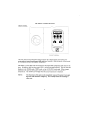
OPERATING MANUAL
EchoThermJ
DIGITAL CHILLING INCUBATOR
MODEL IN/IN-VDC
DOCUMENT NUMBER IN-
TABLE OF CONTENTS
GENERAL
PAGE
I.
INTRODUCTION
3
II.
WARRANTY
3
III.
RETURN OF ITEMS
3
IV.
CAUTIONS
3, 4
V.
SET UP
4, 5
VI.
GENERAL DESCRIPTION
5
VII.
FRONT AND REAR PANEL
6, 7
VIII.
DISPLAY
8
IX.
SETTING TEMPERATURE, TIMER, AND AUTO-OFF
8, 9
X.
CALIBRATION & POWER FAILURE PROTECTION
10, 11
XI.
OTHER OPERATIONS, RS232
11, 12
OPERATION
I. INTRODUCTION
Congratulations on your purchase of a Torrey Pines Scientific EchoThermJ Model IN30 or
IN40 Digital Chilling Incubator. You will find it easy to use and maintain. Please read
these instructions carefully to insure that you receive the maximum benefit from it.
II. WARRANTY
Torrey Pines Scientific warrants this unit to be free from defects in material and
workmanship for a period of one year from the date of purchase. If repair or adjustment is
necessary within the one year period, and has not been the result of abuse or misuse,
please return the unit, freight prepaid, and correction will be made without charge. Out of
warranty products will be repaired on a charge basis. Be sure to fill in and return the
enclosed warranty registration card.
III. RETURN OF ITEMS
Authorization must be obtained before returning items for any reason. When applying
for authorization, please include data regarding the reason the items are to be returned.
For your protection, items must be carefully packed to prevent damage in shipment and
insured against possible damage or loss. Torrey Pines Scientific will not be liable for
damage resulting from careless or insufficient packing. A 15% restocking charge will be
made on all unauthorized returns.
NOTE: Torrey Pines Scientific reserves the right to make improvements in design,
construction and appearance without notice
IV. CAUTIONS
HEATED SURFACES
The Model IN30/IN40 Chilling Incubator has a temperature range from 4ΕC (39.2ΕF) to
70ΕC (158.0ΕF).
At 70ΕC the wire racks and other metal surfaces inside the chamber
are hot enough to cause burns if touched. Please use care when placing samples into or
removing samples from a heated chamber.
ELECTRICAL
The IN30/IN40 Chilling Incubators are made to operate from a universal, bench top power
supply that takes AC inputs from 100VAC to 260VAC, 50/60Hz and converts that to 12
volts DC for the unit. This make the instrument intrinsically safe since it uses only low
voltage DC to operate.
Even so, take the normal care and precautions one would use
with any electrical appliance.
This product is suitable for installation category II, pollution degree II.
3
ENVIRONMENTAL OPERATING CONDITIONS
The IN30/IN40 is intended for indoor use. Ambient temperatures for the lab should not
exceed the range of 15ΕC to 22ΕC for proper performance of the instrument.
Temperatures from 5ΕC to 40ΕC will not affect the structure of the unit. Maximum relative
humidity of 80% for temperatures up to 31ΕC decreasing to 50% for relative humidity at
40ΕC should not be exceeded.
CONDENSATION
Condensation can occur in the sample chamber when working at very low temperatures for
long
periods in a humid environment. Precautions should be taken to assure that your
samples are not affected. Something as simple as placing a paper towel on the bottom of
the chamber can help. If condensation needs to be completely eliminated, a good amount
of desiccant may be needed. If condensation occurs, it will run toward the front of the
chamber where it can easily be cleared.
GENERAL
The IN30/IN40 is designed for laboratory or field use and for use only as instructed in
this manual. If the instrument is used in a manner not specified by the manufacturer, the
protection provided in the design of the equipment may be impaired.
V. SET UP INSTRUCTIONS
The IN30/IN40 Digital Chilling Incubator is an extremely simple to use, set and forget,
unit. The digital, microprocessor design and PID temperature control will assure that the
correct temperature as set is attained and held . . . exactly.
SET UP
1.
Unpack the unit carefully. Be sure to save the packing material in case the unit
needs to be returned to the factory for service.
2.
The unit weighs 45/65 pounds (20.4 kg/29.4kg), is bulky, and has no handles.
It is best to have two people remove the unit from its box and place it on the lab
bench. Always cradle the unit from the underside. Two people should always be
used to move the unit.
3.
Plug the power supply cable into the jack on the rear of the unit. Plug the line
cord into the power supply. Plug the other end of the line cord into a properly
grounded three-wire outlet of proper voltage.
4.
Position the unit on a bench where it has at least 6" (15.24 cm) clearance from
the back of the unit to the wall, bench or other obstruction. The cooling fan on
the rear of the unit needs to draw air clearly to cool the Peltier unit. Also, there
must be about 12" (30.48 cm) clearance on either side of the unit to allow proper
venting.
5.
Place the wire racks provided into the slots selected.
6.
Turn the unit on by the main On/Off switch on the rear panel. The LCD on the
front panel will illuminate and be in the temperature display mode. The fans on
the rear panel and inside the instrument chamber will start to run. The
instrument is now ready to use.
VI. GENERAL DESCRIPTION
The Torrey Pines Scientific IN30/IN40 Chilling Incubators are digitally controlled, Peltier
driven chilling incubator. Because they are Peltier driven, they have no CFC=s or other
refrigerating gas. Also, being Peltier driven, these units have the ability to heat and cool
and control exactly at or near ambient room temperature. These units can hold
temperatures accurately, and reproduce temperatures exactly. The chamber is molded
ABS plastic and the racks are electropolished steel.
Since the unit is Peltier driven there is a fan in the chamber and one on the rear of the
unit. The internal fan is used to keep the chamber at a uniform temperature throughout.
There is an inner chamber door of clear lexan to help hold the chamber temperature while
viewing the sample.
Temperature is sensed by a microchip inside the chamber. The settable temperature
range is from 4.0ΕC to 70.0ΕC. The unit has a membrane keypad with tactile touch and
audible feedback for setting temperature, timer, and auto-off.
The timer is in hours and minutes when displaying hours. When the timer counts down to
minutes only the display will show minutes and seconds. The timer can be set to 99:99
hours/minutes maximum. When the timer counts to zero, it will sound the audible alarm.
The unit can be set to turn off the heater/chiller at the end of a timed event by using the
AUTO-OFF function.
The IN30/IN40 is supplied with an RS232 port for taking data or for instructing the unit
from a computer. Programming the unit to do complex profiles is possible through the
RS232 port. More information is available on this in a later chapter.
REAR PANEL
The rear panel of the IN30/IN40 has an connector jack for the power supply input, and
the main On/Off switch. In addition, the rear panel has the I/O port for the RS232 and
the reorder label. The I/O port will be discussed later in the chapter on the RS232. The
reorder label tells the model number, serial number, operating voltage of the unit, power
consumption and the address information for Torrey Pines Scientific.
The I/O port will, when used with the proper connector, allow the user to write software to
control the unit remotely by a computer.
This can be simple settings or complex
temperature/time profiles.
VIII. DISPLAY
The display is a liquid crystal type with four 5/8" high digits. When in the temperature
mode there is a decimal between the unit and tenth degree with a AC@ for degrees
centigrade in the last place on the right. When in the timer mode the display will show a
colon between the middle two digits. The display will show only temperature or timer.
In the timer mode the display will show 99:99 hours/minutes maximum settable. When
the timer counts down past the last hour, the display will switch and show
minutes/seconds.
When the display is in the temperature mode, the green LED under the TEMP button will
be on.
When the display is in the timer mode, the green LED under the TIMER button will be on.
IX. SETTING TEMPERATURE, TIMER, AND AUTO-OFF
All of these functions are easily set from the keyboard. Please note that the keyboard has
both tactile and audible feedback.
SETTING TEMPERATURE
1.
Depress and release the TEMP key (if the unit has just been turned on it will
already be in this mode).
2.
Depress and hold the UP or DOWN ARROW until the display scrolls to the target
temperature desired (this range is from 4.0Ε C to 70.0ΕC). Release the arrow
key. The unit will now proceed to the target temperature instructed.
NOTE: The display will now toggle between the target and actual
This will show the user both parameters. The LED under
illuminate only when the actual temperature is displayed.
the minimum temperature of Ε
ΕC the
temperatures.
TARGET will toggle and
Also, note that to achieve
ambient temperature of your laboratory should
not be over Ε
ΕC for the IN and :ºC to ºC for the IN. The units have a
below ambient
temperature range from ambient room temperature. This range is
about ΕC to Ε
ΕC and is load dependent. It may take longer to reach very low
temperatures when the chamber is filled with large samples.
3.
To target a new or different temperature simply depress and hold the UP or DOWN
ARROW until the display shows the new temperature desired. Please
unit must be displaying temperature to do this. If the unit is in the
note that the
timer mode then the
TEMP key must be depressed first.
4.
To turn off the target temperature the unit has to be turned off at the AC input.
Scrolling the target temperature back to room temperature will cause the unit to
target this as a new temperature. Only turning the unit off and on again will
remove the target temperature.
The user can easily see if a target temperature exists by seeing if the TEMP LED
is flashing. The only exception to this is when AUTO-OFF is used. When AUTOOFF is activated and the timer counts down to zero, the heater/chiller will
turn off and
will not
LED is not
have a target temperature (note at this point that the TEMP
toggling).
SETTING TIMER
1.
Depress and release the TIMER key. This will shift the display to the timer mode.
2.
Depress and hold the UP ARROW until the time wanted is in the display.
Depressing and holding the DOWN ARROW will move the timer setting to a lower
value. When the UP or DOWN ARROW is released the timer will start to count
down to zero. When the timer counts down to zero the audible alarm will sound
ten times.
NOTE: Switching between TIMER and TEMP on the display can be done any
time during a run without affecting the target temperature or timer. To
do this,
simply depress and release either the TEMP or TIMER keys.
SETTING AUTO-OFF
AUTO-OFF is an on/off toggle key which activates the AUTO-OFF function. When the
key is depressed, the AUTO-OFF light will come on. This then tells the heater/chiller to
turn off when the timer counts down to zero. If no timer value is set, the AUTO-OFF
function will not have any affect on the operation of the unit. Also, AUTO-OFF can be
deactivated at any time during a timer count down without affecting the timer.
1.
Depress and release the AUTO-OFF key. This activates this function and
illuminates the Auto-Off LED and tells the unit to turn off the heater/chiller when
the timer counts down to zero.
2.
To turn off this function, simply depress and release the AUTO-OFF key again.
The AUTO-OFF LED will go off.
X. CALIBRATION & POWER FAILURE PROTECTION
NOTE: The unit stores calibration and target temperature information in memory even
through power failures. The temperature calibration is set at the factory and should be
accurate enough for most applications. However, the user may wish to calibrate the unit
to his own standard. This can be done in the field following the instructions below. The
calibration may be done at a single point or at two separate temperatures for straight line
interpolation.
CALIBRATION
Single point calibration is used for maximum accuracy. However, the unit is sent to the
user with two point calibration for accuracy at every temperature. If single point calibration
is used be sure to clear the memory first. Follow the instructions below for both single
point and two point calibration. If single point calibration is used, then the calibration
must be reset each time the target temperature is set. The calibration set at the
factory (two-point) is very accurate and should do well for all applications.
Single Point Calibration
1.
Clear the calibration in memory by first turning the unit off. Then depress and hold
the TIMER key while turning the unit on again. The memory will now be cleared.
2.
Set the unit to the target temperature to be calibrated. Measure the chamber
temperature using your laboratory standard. Be sure to allow the chamber and
your thermometer time to equilibrate at the target temperature you desire.
3.
Push and hold the TIMER key for five seconds until the display shows the
chamber temperature of the instrument.
4.
Touch the UP or Down arrow until the temperature in the display of the IN30/IN40
agrees with the temperature as measured in the chamber by your standard.
5.
Touch the TIMER key again. After a second or two the unit will display all zeros.
Touch the TEMP key and the display will show the target and actual temperatures.
The unit is
now calibrated at that temperature.
Two Point Calibration
For two point calibration, one calibration temperature must be above 37.0 C and the other
must be below 37.0 C. For best results, use temperatures around 10.0 C and 60.0 C.
Follow the calibration procedure as for a single point. Then repeat the procedure at the
second point. When you calibrate the second point, the calibration of the first point is not
affected. However, all other temperatures will adjust to a straight -line through the two
calibration points.
NOTE: Measuring the chamber temperature is easy to do, but not necessarily accurately.
Generally speaking, glass thermometers found around a lab are not accurate enough or
readable enough to do a good job. Good, certified glass thermometers are available from
lab supply dealers as are fairly accurate digital thermometers.
POWER FAILURE PROTECTION
The IN30/IN40 stores the targeted temperature in memory. If power fails and returns, the
unit will return to the temperature it was running before the power failure. Also, the
AUTO-OFF light will be flashing to tell the user that a power interruption has occurred. To
turn off the AUTO-OFF light simply touch the TEMP key. The user can then determine if
the interruption has caused a problem with the samples being run. It should be noted that
the unit does not distinguish between a power interruption and when the unit is
intentionally turned off. Therefore, when the unit is turned back on, it will go back to the
target temperature that was running before the unit was turned off.
XI. OTHER OPERATIONS
The IN30/IN40 Chilling Incubator has been designed with an RS232 interface. The port
is on the rear of the unit and is a standard D subminiature connector. This interface is
input and output. This means that the unit can be controlled remotely from a computer to
perform any number of procedures or routines as complicated as you wish. The interface
also can be used to collect data from the unit for record keeping or for regulatory agencies
as needed. The instructions for connection and use follow.
RS232 INTERFACE SPECIFICATION
Parameters: 2400 baud, 8 data bits, 1 stop bit, no parity. No handshake hardware or
software is necessary. It will work well on a Windows terminal program per these settings.
All communications settings and queries are done using ASCII characters with the
carriage return as the terminating character (CR1).
Pins in use on the RS232 jack are:
Pin 2 - RXD (data from incubator to PC)
Pin 3 - TXD (data from PC to incubator)
Pin 5 - Ground
Query
Command
Request current temperature
a
Request current timer
b
Request auto mode status
c
Request target temperature
d
For example: to request current temperature program you need to send two characters:
aCR where ACR@ is carriage return.
and the unit responds xx.xCR, where xx.x is the present temperature.
Note: If there is no Target Temperature, the unit will send the message A no target
set@CR
Auto status is reported as A Auto On@CR or AAuto Off@CR
Set
Command
Target Temperature
A
Timer
B
Auto
C
Change display to temperature indicator
D
Change display to Timer indicator
E
For example:
To set a temperature target of 50.0ΕC , the command string is as follows:
A(space)50.0CR
To set a Timer for one hour:
B(space)010000CR
To set Auto-off on
C(space)ONCR
To set Auto-off off
C(space)OFFCR
To change the display mode to temperature indicator
D(space)CR
To change the display mode to timer indicator
E(space)CR
If the command string is valid the unit will respond with the message ACommand OK@CR
and if the command is incorrect A Command Failed@CR