1
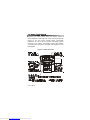
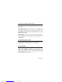
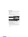
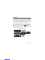
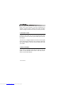
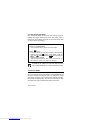
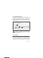
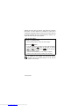
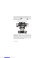
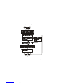
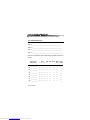
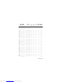
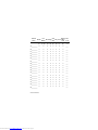
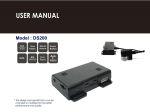
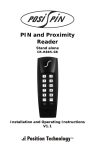
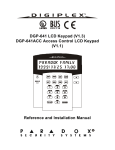
Digiplex LCD Keypad
DGP-641
User’s Manual
Downloaded from www.Manualslib.com manuals search engine
Downloaded from www.Manualslib.com manuals search engine
TABLE OF CONTENTS
1.0 INTRODUCTION ........................................................ 7
1.1 Legend ...................................................................... 7
2.0 BASIC OPERATION .................................................. 8
2.1 Auditory Feedback (Beep Tones) ............................. 9
2.2 Keypad Indicator Lights ............................................. 9
2.3 LCD Screen ............................................................... 9
2.4 User Menu ................................................................ 11
2.5 Partitioned System ................................................... 12
2.6 Area Status Display .................................................. 12
3.0 ARMING .................................................................... 14
3.1 Exit Delay Timer ....................................................... 14
3.2 Regular Arming ........................................................ 14
3.3 Stay Arming .............................................................. 15
3.4 Instant Arming .......................................................... 16
3.5 Force Arming ............................................................ 17
3.6 One-Touch Buttons .................................................. 19
3.7 Keyswitch Arming ..................................................... 20
3.8 Auto-Arming ............................................................. 20
3.9 Bypass Programming ............................................... 21
4.0 DISARMING .............................................................. 24
4.1 Entry Delay Timer .................................................... 24
4.2 Disarming an Armed System ................................... 24
4.3 Alarm Memory Display ............................................. 26
Downloaded from www.Manualslib.com manuals search engine
5.0 ACCESS CODES ......................................................27
5.1 Keypad Lock-out ...................................................... 27
5.2 Erasing Access Codes ............................................. 27
5.3 System Master Code ................................................ 28
5.4 User Access Codes ................................................. 28
6.0 TROUBLE DISPLAY .................................................34
6.1 Event Record Display .............................................. 39
7.0 ADDITIONAL FEATURES ........................................41
7.1 Programmable Outputs (PGMs) .............................. 41
7.2 Keypad Settings ....................................................... 41
7.3 Set Time & Date ....................................................... 43
7.4 Programming Chime Zones ..................................... 43
7.5 Panic Alarms ............................................................ 45
7.6 Quick Function Buttons ............................................ 46
7.7 Access Control ......................................................... 46
8.0 FIRE AND BURGLAR ALARMS ..............................47
8.1 Standard Fire Zone .................................................. 47
8.2 Delayed Fire Zone ................................................... 47
8.3 Fire Safety Tips ........................................................ 50
8.4 Minimizing Home Fire Hazards ................................ 50
8.5 Home Fire Warning System ..................................... 51
8.6 Burglar Alarm ........................................................... 51
Downloaded from www.Manualslib.com manuals search engine
9.0 TESTING AND MAINTENANCE .............................. 52
9.1 Burglar Alarm Testing .............................................. 52
9.2 Fire Alarm Testing .................................................... 52
9.3 System Maintenance ................................................ 52
9.4 System Test ............................................................. 53
10.0 SYSTEM CHECKLIST ............................................ 54
10.1 Zone Description .................................................... 54
10.2 Access Codes ........................................................ 57
10.3 Special Buttons and Features ................................ 63
10.4 Other Information ................................................... 64
Downloaded from www.Manualslib.com manuals search engine
6 User’s Manual
Downloaded from www.Manualslib.com manuals search engine
1.0 INTRODUCTION
Your Security System is an advanced technology security
system that will provide you with reliable security protection and
powerful features that are easy to use. The elegant and userfriendly LCD Keypad will allow you easy access to your security
system's functions and information at the touch of a button. The
32-character LCD screen will display messages and menus to
guide you through the system’s operations. Your installer can
even customize the messages for your home or business.
Since you will communicate your instructions to your system
through the keypad, please read this manual carefully and have
your installer explain basic system operation.
1.1 LEGEND
Indicates a warning or an important note.
Indicates useful information or tip.
[WORD ]
[NUMBER]
keypad.
Indicates information that must be entered on the
Italics
Indicates references to features, options or sections.
LCD Keypad 7
Downloaded from www.Manualslib.com manuals search engine
2.0 BASIC OPERATION
Everything you need to know about your security system is
clearly displayed on the large LCD screen. The menus and the
prompt on the LCD screen provide simple, step-by-step
instructions on how to use your system and display what is
occurring in your system. The following sections will introduce
you to the roles of the buttons, the lights, and messages on your
LCD Keypad.
Figure 2-1: Basic Overview
8 User’s Manual
Downloaded from www.Manualslib.com manuals search engine
2.1 AUDITORY F EEDBACK (BEEP T ONES)
When you enter information on the keypad, the keypad will guide
you with beep tones to communicate acceptance or rejection of
your entries.
Confirmation Beep: When an operation (i.e. arming/disarming)
is successfully entered or when the system switches to a new
status/mode, the keypad emits an intermittent beep tone (“BEEPBEEP- BEEP- BEEP- BEEP”).
Rejection Beep: When the system reverts to previous status, or
when an operation is incorrectly entered, the keypad emits a tone
(“ BEEEEEEEEEEP”).
2.2 KEYPAD I NDICATOR LIGHTS
The state of the two colored lights on the keypad (see Figure 2-1
page8) represents a specific condition in your system.
2.3 LCD S CREEN
The LCD (liquid crystal display) is a 32-character screen that
communicates messages, instructions, and the status of your
system. The backlight, contrast, and scrolling speed are
adjustable (see section 7.2). Your installer can customize many of
the messages to suit your needs.
LCD Keypad 9
Downloaded from www.Manualslib.com manuals search engine
2.3.1 Normal Mode
When no actions are being performed on the keypad, the keypad will
remain in Normal Mode as shown in Figure 2-2 on page10 and will
automatically display:
• The current status of the zones for every area the keypad is
assigned
• The Alarm Memory Display (see section 4.3) if any alarms have
occurred
• The Trouble Display (see section 6.0) if any troubles are occurring
• The current state of the Indicator Lights
Figure 2-2: Normal and Confidential Mode
2.3.2 Confidential Mode
The installer can program keypads not to display the status of your
system automatically by changing the LCD screen to Confidential
Mode. In Confidential Mode:
• The zones and status messages will NOT be displayed
• The Indicator Lights will not illuminate
• Depending on how your keypad was programmed by the installer,
you must either press a button or enter your User Access Code to
illuminate the Indicator Lights and activate Normal Mode.
10 User’s Manual
Downloaded from www.Manualslib.com manuals search engine
2.4 USER M ENU
Once you enter your User Access Code and are granted access
to the system, the LCD screen will display the User Menu as
shown in Figure 2-3. From this menu you can access various
features and other menus. Depending on the User Options
programmed on your User Access Code , you will have access to
some or all of the features and menus in the User Menu .
Press the desired Action Button (see Figure 2-1, page8), or
scroll through the menu by using the
and
buttons on
the right of the keypad and press the
button. Once you
have completed an action (i.e. arming, disarming, etc.), the LCD
screen will return to Normal Mode.
Figure 2-3: User Menu
LCD Keypad 11
Downloaded from www.Manualslib.com manuals search engine
2.4.1 Multiple-action
The Multiple-action feature permits you to complete more than one
action after entering the User Menu. If your installer has enabled this
feature, the LCD screen will return to the User Menu after each
action so you may perform another action without re-entering your
User Access Code. Press the
button to exit the User Menu.
2.5 PARTITIONED SYSTEM
Your installer can design your system to recognize up to four
separate protected areas. A separated system is called a
Partitioned System, which can be useful in situations where
shared security systems are more practical. For example, a
company that has both an office area and a warehouse area can
arm and disarm each area separately and control the access to
each area. Therefore, one person may have access to only one
area, whereas another person may have access to all areas.
Access to the areas is determined by the User Access Code .
2.6 AREA STATUS DISPLAY
In Area Status Display you will be able to see the status of the
areas in a Partitioned System (see section 2.5) for the area(s)
the keypad is assigned. If your LCD screen is in Confidential
Mode (see section 2.3.2), you must first press a button or enter
your User Access Code to activate Normal Mode depending on
how your keypad is programmed.
12 User’s Manual
Downloaded from www.Manualslib.com manuals search engine
How do I see the status of the zones?
1) Enter [ ACCESS CODE] then press the button corresponding to
the area:
= Area 1
= Area 3
= Area 2
= Area 4
2) Press
to exit.
In Area Status Display the following will scroll on the LCD
screen:
•
•
•
•
•
“ready” if all zones in the selected area are closed
“not ready” if zones in the selected area are open
open zones within that area
“Trouble(s)” (see section 6.0) if a trouble has occurred
“Alarms in Memory” (see section 4.3) if an alarm has occurred
LCD Keypad 13
Downloaded from www.Manualslib.com manuals search engine
3.0 ARMING
When the system is armed, the alarm system will respond to any
breach in the zones according to the zone’s programming. For
example, if someone opens a window that is armed, the alarm
system will trigger the alarm and can alert your Security Company.
3.1 EXIT DELAY T IMER
When you arm the system, it will start the Exit Delay Timer to
provide you with enough time to exit the protected area before
the system is armed. The Status Light will flash green while the
time elapses.
The timer can be assigned different time limits and the keypad
can be programmed to display the time remaining and/or beep
while the time elapses on the timer. Discuss these options with
your installer.
3.2 REGULAR A RMING
This method is used for the everyday arming of the system. All
zones within the protected area must be closed to arm the
system. To check the status of the zones in each area, refer to
section 2.6 Area Status Display.
14 User’s Manual
Downloaded from www.Manualslib.com manuals search engine
How do I Regular Arm the system?
1) Enter your [ ACCESS CODE].
After Confirmation Beep, “Valid Code” should appear.
2) Press the
button.
If you have access to more than one area, press the area’s
number, press the
button for all areas, or use the
and
buttons and press
when the area you
want to arm appears.
After the Confirmation Beep, “Regular Arming” should appear
on the LCD screen and the exit delay timer will begin the
countdown to arming.
If enabled by the installer, the One-Touch Buttons
(section 3.6) or a keyswitch (section 3.7) can also be
used to arm the area.
3.3 STAY ARMING
Stay Arming will partially arm your system to permit you to
remain in the protected area. Based on your instructions, your
installer will program specific zones as Stay Zones. These zones
will not arm when you Stay Arm. For example, you can arm your
doors and windows at home without arming the motion detectors
so you will be protected while you sleep. Only User Access
Codes with the Stay and Instant Arm option enabled can Stay
Arm the system. Also, see section 3.8 Auto-Arming for another
everyday arming option.
LCD Keypad 15
Downloaded from www.Manualslib.com manuals search engine
3.3.1 Stay Arming with Delay
Stay Arming with Delay functions like Stay Arming except the
installer can program armed zones with an Entry Delay Timer. If
these zones are accidently triggered, the timer will start to allow
you time to disarm the area(s).
How do I Stay Arm?
1) Enter your [ ACCESS CODE].
After Confirmation Beep, “Valid Code” should appear.
2) Press
button.
If you have access to more than one area, press the area’s
number, press the
button for all areas, or use the
and
buttons and press
when the area you
want to Stay Arm appears.
After the Confirmation Beep, “Stay Arming” should appear on
the LCD screen and the exit delay timer will begin.
If enabled by the installer, the One-Touch Buttons (section
3.6) or a keyswitch (section 3.7) can be used to arm the area.
3.4 INSTANT ARMING
This feature is similar to Stay Arming. Instant Arming will partially
arm your system to permit you to remain in the protected area, but
all zones, including the entry/exit point, are changed to instant
alarm zones. Therefore, if any armed zone is breached, the alarm
will instantly be triggered. Only User Access Codes with the Stay
and Instant Arm option enabled will be able to Instant Arm.
16 User’s Manual
Downloaded from www.Manualslib.com manuals search engine
3.4.1 Instant Arming with Delay
Instant Arming with Delay functions like Instant Arming except
the installer can program certain armed zones within the
protected area(s) with an Entry Delay Timer. If these zones are
accidently triggered, the timer will start to allow you enough time
to disarm the area(s).
How do I Instant Arm?
1) Enter your [ ACCESS CODE].
After Confirmation Beep, “Valid Code” should appear.
2) Press the
button.
If you have access to more than one area, press the area’s
number, press the
button for all areas, or use the
and
buttons and press
when the area you want
to Instant arm appears.
After the Confirmation Beep, “Instant Arming” will appear
briefly on LCD screen and the exit delay timer will begin.
If enabled by the installer, the One-Touch Buttons
(section 3.6) or a keyswitch (section 3.7) can also be
used to arm the area.
3.5 FORCE A RMING
Force Arming allows you to arm your system when specific
zones are open. Certain zones can be programmed by the
installer to remain unarmed when you initiate Force Arming.
Once the open zone is closed, however, the system will then arm
it as well. Only User Access Codes with the Force Arm option
LCD Keypad 17
Downloaded from www.Manualslib.com manuals search engine
enabled can Force Arm the system. This feature is commonly
used when a motion detector is protecting an area that is
occupied by a keypad. During Force arming, the motion detector
will remain unarmed until you exit the area that it protects. The
system will then arm the motion detector.
How do I Force Arm?
1) Enter your [ ACCESS CODE].
After Confirmation Beep, “Valid Code” should appear.
2) Press the
button.
If you have access to more than one area, press the area’s
number, press the
button for all areas, or use the
and
buttons and press
when the area you
want to Force Arm appears.
After the Confirmation Beep, “Force Arming” will appear
briefly on LCD screen and the exit delay timer will begin.
If enabled by the installer, the One-Touch Buttons
(section 3.6) or a keyswitch (section 3.7) can also be
used to arm the area.
18 User’s Manual
Downloaded from www.Manualslib.com manuals search engine
3.6 ONE-T OUCH BUTTONS
At the touch of a button you can view the Area Status Display
(see section 2.6) for a Partitioned System (see section 2.5).
Press and hold:
Your installer can also program your system to respond to
certain features with just a touch of a button. You will then have
access to the following features without using your User Access
Code by pressing and holding the desired button.
Press and hold:
For more information on these features, please refer to their
sections.
LCD Keypad 19
Downloaded from www.Manualslib.com manuals search engine
3.7 KEYSWITCH ARMING
Your installer can add a keyswitch to arm and disarm your
system. The keyswitch can be programmed to Regular, Stay,
Force, or Instant Arm, and Disarm a specific area. The keyswitch
will also be programmed by the installer to function as a
Maintained or Momentary keyswitch.
3.7.1 Maintained Keyswitch
To arm the system, place in the “on” position.
To disarm the system, place in the “off” position.
3.7.2 Momentary Keyswitch
To arm the system, place in the “on” position briefly then place it back
in the “off” position. Repeating this process will disarm the system.
3.8 AUTO-ARMING
Your installer can program your system to allow you to arm your
system automatically if specific conditions occur.
3.8.1 Timed Auto-Arming
If enabled, you can set the time that an area will arm itself
automatically.
20 User’s Manual
Downloaded from www.Manualslib.com manuals search engine
How do I set the Auto-Arming timer?
1) Enter your [ ACCE SS CODE].
After Confirmation Beep, “Valid Code” should appear.
2) Press the
button.
3) Press the
button.
If you have access to more than one area, press the area’s
number or use the
and
buttons and press the
button when the area you want to program appears
on screen.
4) Enter the [ TIME] you want the area to be armed according to
the 24-hour clock (i.e. 9 a.m. is 09:00 and 9 p.m. is 21:00).
5) Press the
button to save and exit.
3.8.2 No Movement Auto-Arming
Your system can be programmed to send a report to the Security
Company and/or arm the system if there is no activity in the area
during a specified period of time. Speak to your installer about this
feature.
3.9 BYPASS PROGRAMMING
The installer can program certain zones with the bypass option
so you can program the system to bypass certain zones when
you arm the protected area. When a zone is bypassed, it will
remain unarmed once the system is armed. This option may be
useful, for example, when renovating part of the protected area.
LCD Keypad 21
Downloaded from www.Manualslib.com manuals search engine
Bypassed zone(s) will be kept in memory until the area is armed.
Once the area is disarmed, the system will unbypass the zones.
To bypass a zone:
• The zone must have the Bypass option programmed by the
installer.
• Your User Access Code must be programmed to enable the
Bypass option.
• Your User Access Code must have access to the zone's Area
Assignment.
Fire Zones cannot be bypassed.
3.9.1 Zone Bypass
How do I bypass a zone?
1) Enter your [ ACCE SS CODE].
After Confirmation Beep, “Valid Code” should appear.
2) Press the
button.
3) Enter the zone number or use the
and
buttons
and press
once the zone you want to bypass appears.
If “zone bypassed” does not appear on the screen and the keypad emits the Rejection Beep, the zone may not have the
bypass feature enabled.
4) Press the
22 User’s Manual
Downloaded from www.Manualslib.com manuals search engine
button to exit.
3.9.2 Bypass Recall
Bypass Recall reinstates all the zones that were bypassed the last
time the system was armed.
How do I activate Bypass Recall?
1) Enter your [ ACCE SS CODE].
After Confirmation Beep, “Valid Code” should appear.
2) Press the
button.
3) Press the
button.
Zones bypassed during the last time the system was armed are
bypassed.
4) Press the
button to exit.
If you have a Partitioned System , only the zones in the
area(s) assigned to your User Access Code will be
affected.
Use the
and
buttons if you want to verify which zones
were bypassed the last time the system was armed after you
press the
button (Step 3). “Bypassed” or “Zone Normal” will
appear below the zones. If you want to unbypass a zone or vice
versa, press the
button.
LCD Keypad 23
Downloaded from www.Manualslib.com manuals search engine
4.0 DISARMING
When the system is disarmed, the alarm system deactivates the
zones so the alarm will not be triggered if zones are breached.
Any user can disarm the system unless their code has been
assigned the Arm Only option.
4.1 ENTRY D ELAY T IMER
Your installer will program designated entry points (i.e. the front
door) with an entry delay. This delay will allow you enough time
to enter your code to disarm the system before the alarm is
triggered.
4.2 DISARMING AN A RMED SYSTEM
You can only disarm the area to which your User Access Code is
assigned. User Access Codes with the Arm Only option cannot
disarm area(s).
24 User’s Manual
Downloaded from www.Manualslib.com manuals search engine
How do I disarm the system?
If you are disarming a Stay or Instant Armed area, go to step 2.
1) Enter through a designated entry.
The keypad will beep and begin the Entry Delay Timer.
2) Enter your [ ACCE SS CODE].
3) Press the
button.
If you have access to more than one area, press the area’s
number, press the
button for all areas, or scroll and
press
when the area you want to disarm appears.
After Confirmation Beep, “Success Disarm” should appear on
LCD screen.
If enabled by the installer, a One-Touch Button (section
3.6) or a keyswitch (section 3.7) can also be used to
disarm the area.
How do I disarm an accidentally triggered system?
1) Enter your [ ACCE SS CODE].
2) Call your Security Company quickly to advise them of the false
alarm.
LCD Keypad 25
Downloaded from www.Manualslib.com manuals search engine
4.3 ALARM M EMORY DISPLAY
Your system will record all the alarms that occurred during the
last armed period. If an alarm was triggered, the keypad will
display “Alarms in Memory” .
In case of a burglar alarm, leave the premises and
call your Security Company from a safe place.
How do I view the list of the alarms that occurred?
When an alarm has occurred, the LCD screen will display
“Alarms in Memory [ MEM ] to View”.
1) Press the
button.
Each zone whose alarm was triggered will appear below “Alarm in:”.
2) Press the
button to exit the Alarm Memory Display.
The zones in alarm will remain in the Alarm Memory until
the next time that area is armed.
26 User’s Manual
Downloaded from www.Manualslib.com manuals search engine
5.0 ACCESS CODES
Access Codes allow access the system. These codes can be
programmed to permit access to all or some features and areas.
The installer will program User Access Codes to be four digits,
six digits, or variable from one to six digits in length. Each digit
can be any value between zero and nine. If the installer
programmed your system to accept a variable code length, you
may have to press the
button after entering their User
Access Code. Only the System Master Code cannot be less than
4 digits.
5.1 KEYPAD L OCK-OUT
If a consecutive number of invalid codes are entered on the
keypad, the installer can program the system to lock-out access
from the keypad for a specified period of time.
5.2 ERASING A CCESS CODES
To delete existing Access Codes, follow the directions in Figure
5-2 on page30, but press the
button in Steps 5, 6, and 7.
Once the information is erased, press the
button to save
and exit.
LCD Keypad 27
Downloaded from www.Manualslib.com manuals search engine
5.3 SYSTEM MASTER CODE (Default 123456)
The System Master Code will give you access to all the features
available on your system as well as the ability to add, modify, or
delete any User Access Codes. We suggest that you change this
code to prevent others from accessing and changing your
options without authorization.
How do I change the System Master Code?
1) Enter the current [ SYSTEM MASTER CODE].
After Confirmation Beep, “Valid Code” should appear.
2) Press the
button.
3) Press the
button.
“User code [ ] Enter a number” should appear on LCD screen.
4) Enter the numbers [0] and [1].
5) Enter a [ NEW CODE].
6) Press the
button to exit.
5.4 USER A CCESS CODES
Your system supports up to 95 User Access Codes. Codes are
given a User Number between 02 and 96 (User Number 01 is the
System Master Code).User Access Codes can be programmed
with various options that will allow you to control the access to
your system. The System Master Code and codes with the
Master feature can program User Access Codes with their User
Options and Area Assignment.
28 User’s Manual
Downloaded from www.Manualslib.com manuals search engine
If the keypad emits a Rejection Beep once you have
completed all the steps, you may have chosen an existing
User Code or the Master code used to modify or create the
code does not have access to the User Options or Area
Assignment programmed.
You grant users access to the features or areas by turning ON or
OFF the number corresponding to the option or area. The option
is considered ON when the number appears within the brackets.
You turn options ON and OFF by pressing the number buttons
on the keypad (see example Figure 5-1).
Figure 5-1: Example of Activating Options
LCD Keypad 29
Downloaded from www.Manualslib.com manuals search engine
Figure 5-2: Programming User Access Codes
30 User’s Manual
Downloaded from www.Manualslib.com manuals search engine
Table 1: User Options
Options on the User Access Codes that activate access to
features.
Press option on/off Option Description
off
off
on
off
on
on
off
on
off
on
Master feature disabled.
Master feature enabled.
Modifies User Code only.
Full Master feature enabled.
Create or modify other User Codes, User
Options, and Area Assignment according
to its own User Options and Area
Assignment.
Duress feature disabled.
Duress feature enabled.
Can arm, disarm, and send a silent alarm
to the Security Company. For use when
someone forces you to arm or disarm
areas.
Bypass feature disabled.
Bypass feature enabled.
Can deactivate zones using the Bypass
feature
LCD Keypad 31
Downloaded from www.Manualslib.com manuals search engine
Press option on/off Option Description
off
on
off
on
off
on
off
on
32 User’s Manual
Downloaded from www.Manualslib.com manuals search engine
Arm Only feature disabled.
Arm Only feature enabled.
Can arm assigned areas, but CANNOT
disarm.
Stay & Instant Arm feature disabled.
Stay & Instant Arm feature enabled.
Can Stay or Instant Arm the system
Force Arm feature disabled.
Force Arm feature enabled.
Can Force Arm the system.
User Access Code obeys the keypad's
area assignment in a Partitioned System.
When you enter your User Access Code,
the keypad will permit access only to areas
it controls.
Keypad obeys the User Access
Code's area assignment.
The keypad will permit access to all the
areas assigned to the User Access Code
regardless which areas the keypad
controls.
Table 2: Area Assignment
In a Partitioned System the system can be divided into four
distinct protected areas. Programming access to a specific area
or areas is called Area Assignment. User Access Codes are only
able to perform actions (arming, disarming, etc.) in the area(s)
the code is assigned.
Press button on/off Area Assignment
on
on
on
on
All four buttons off
Access to Area 1
Access to Area 2
Access to Area 3
Access to Area 4
Controls PGMs only (if PGMs are
programmed by the installer).
When the area's number is OFF, the User Access Code
does not have access to that protected area.
LCD Keypad 33
Downloaded from www.Manualslib.com manuals search engine
6.0 TROUBLE DISPLAY
If your system is tampered with or experiences problems, the
Trouble Display will appear on the LCD screen. Most of the trouble
conditions can be programmed by your installer to be reported
directly to your Security Company. A keypad will only display
troubles that occur in the area(s) to which it has been assigned.
Potential troubles have been sorted into eight groups. The
messages that the LCD screen will display after experiencing the
trouble are listed below with a brief explanation of the cause.
We strongly suggest that you inform your Security
Company of the trouble and allow them to service your
system.
How do I view the Trouble Display?
1) When in Normal Mode (see section 2.3.1) and “Trouble(s)
[TRBL] to View” appears on the LCD screen.
2) Press the
button.
The Group heading will appear with the particular trouble
causing the problem. The Troubles by Group are listed below.
3) Use the
and
buttons to view the specific trouble.
If your keypad is in Confidential Mode (see section 2.3.2), “Troubles
[TRBL] to View” will not appear on the LCD screen until you enter
your User Access Code or press a button, depending on how your
keypad was programmed.
34 User’s Manual
Downloaded from www.Manualslib.com manuals search engine
6.0.1 Group 1: System
AC Failure
The control panel has detected a power failure. This means that your
system is running on the back-up battery. This trouble can be
programmed not to appear on the LCD screen when it occurs. The
AC Light on your keypad will be turned off during a power failure. If
this trouble occurs when your establishment is not experiencing a
power failure, call your Security Company for repairs.
Battery Trouble
The back-up battery is disconnected, needs to be recharged, or
replaced.
AUX Current Limit
Devices connected to the control panel have exceeded current limits.
The Auxiliary Output will shutdown until the trouble has been
rectified.
Bell Current Limit
The bell or siren connected to the control panel has exceeded
current limits. The Bell/Siren Output will be shutdown until the trouble
is rectified.
Bell Absent
The control panel has detected that the bell or siren is not connected.
ROM check Error
The control panel registers a memory error.
LCD Keypad 35
Downloaded from www.Manualslib.com manuals search engine
6.0.2 Group 2: Communicator
TLM (Telephone Line Monitor)
The control panel is unable to access the telephone line.
Fail to Communicate 1
Fail to Communicate 2
Fail to Communicate 3
Fail to Communicate 4
The control panel has tried all assigned telephone numbers and has
failed to communicate with the Security Company.
Fail to Communicate PC
The control panel is unable to communicate with the Security
Company's diagnostic software.
6.0.3 Group 3: Modules Trouble
Module Tamper
The control panel registers that someone has triggered the tamper
switch on a module.
ROM Check Error
The control panel registers a memory error in a module.
TLM Trouble
A module is unable to access the telephone line.
Fail to Communicate
A module has failed to communicate with the Security Company.
Printer Trouble
The control panel registers a problem with the printer. Check printer
for problems (paper jam, no paper, no power, etc.) before calling
installer.
36 User’s Manual
Downloaded from www.Manualslib.com manuals search engine
AC Failure
Module power failure.
Battery Failure
Module's battery is disconnected, needs to be recharged, or
replaced.
Supply Output
Module has exceeded current limits.
6.0.4 Group 4: Bus Troubles
Missing Keypad
A keypad is no longer communicating with the control panel.
Missing Module
A device no longer communicating with the control panel.
Safety Mismatch
A locked module is installed on the bus and its locking code does not
match that of the control panel. System cannot be armed.
General Failure
No communication between devices and the control panel.
Bus Overload
Too many devices are connected on the Bus.
Bus Communication Error
The Bus is having difficulty communicating with the devices and the
control panel.
6.0.5 Group 5: Zone Tamper
The zone or zones that were tampered with will be displayed on the
LCD screen.
LCD Keypad 37
Downloaded from www.Manualslib.com manuals search engine
6.0.6 Group 6: Zone Low Battery
If a wireless device's battery needs to be replaced, the zone that it is
assigned to will be displayed on the LCD screen. Also, the light on
the device will flash to indicate this trouble.
6.0.7 Group 7: Zone Fault
A wireless device is no longer communicating with its receiver or a
Fire Loop connection trouble is occurring.
6.0.8 Group 8: Clock Loss
The time and date have been reset to the default. This is the only
trouble that we recommend that you correct. “Clock Loss [8] to Set”
will appear on the LCD screen after you press the
button.
To correct the date and time from Normal Mode, enter your
[ ACCESS CODE ], press the
button, then follow the
instructions below.
How do I reset the time and date?
1) Press the
button.
2) To change the time, place the underline under the desired
number by using the
button and enter the hour and
minutes according to the 24-hour clock (i.e. 9pm is 21:00).
3) To change the date, place the underline under the desired number and enter the correct date according to year/month/day.
4) Press the
38 User’s Manual
Downloaded from www.Manualslib.com manuals search engine
button to exit.
6.1 EVENT RECORD DISPLAY
The Event Record Display will record the user-initiated actions
that occurred in your system as well as any alarms or troubles.
For example, when a valid code is entered, the User Access
Code and the action taken (arm, disarm, etc.) is recorded.
You have the choice to view the events in all the areas assigned
to your User Access Code or by individual area. In either case
the most recent event is displayed first (see Figure 6-1).
You will only be able to view the events that occurred in
the areas assigned to your User Access Code.
How do I view the Event Record?
1) Enter your [ ACCESS CODE].
2) Press the
button.
3) To view events:
Press the
button for all areas
Press the
button for only the First Area
Press the
button for only the Second Area
Press the
button for only the Third Area
Press the
button for only the Fourth Area
4) Use the
button to view subsequent events.
5) Press the
button to exit.
LCD Keypad 39
Downloaded from www.Manualslib.com manuals search engine
Once you have entered the Event Record Display, you can
change the order that the Event Record screens (see Figure 6-1)
appear by pressing the
button. If you already know the
number of the event you want to view, press the
button and
then enter the event's number.
Figure 6-1: Event Record screens
Messages like “First Area” and “Code 01” shown in Figure 6-1 are
pre-programmed messages that your installer may have
customized to suit your system. For example, “First Area” could be
replaced by “Warehouse”. The Number of the Event may cut off
the last few letters of these custom messages. For example,
“Warehouse” may appear as “Wareh001”.
40 User’s Manual
Downloaded from www.Manualslib.com manuals search engine
7.0 ADDITIONAL FEATURES
7.1 PROGRAMMABLE OUTPUTS (PGMS)
Your system includes five programmable outputs (PGMs) that
can be programmed by your installer. A PGM triggers when a
predetermined event or series of events occurs in your system.
The PGMs can be programmed to reset smoke alarms, turn on
light switches, open or close garage doors and much more. Ask
your installer about this useful feature.
7.2 KEYPAD S ETTINGS
You can modify the keypad settings to suit your needs (see
Figure 7-1).
1) Scrolling Speed is how long the messages stay on the screen
before moving to the next message.
2) Backlight refers to the illumination behind the buttons and
LCD screen.
3) Contrast refers to how dark or pale characters on the screen
will appear.
LCD Keypad 41
Downloaded from www.Manualslib.com manuals search engine
Figure 7-1: Modifying LCD screen settings
42 User’s Manual
Downloaded from www.Manualslib.com manuals search engine
7.3 SET T IME & DATE
If the wrong time and /or date are displayed on the Normal Mode
screen, you can reset them.
How do I reset the time and date?
1) Enter your [ ACCESS CODE] and press the
2) Press the
button
button.
3) To change the time, place the underline under the number
you want to change by using the
button and enter the
hour and minutes according to a 24-hour clock (i.e. 9 a.m. is
09:00 and 9 p.m. is 21:00).
4) To change the date, place the underline under the number
you want to change and enter the correct date according to
year/month/day.
5) Press the
button to exit.
7.4 PROGRAMMING C HIME Z ONES
You can program the keypads to emit a rapid, intermittent beep
whenever designated zones are opened or only when opened
between certain hours. These zones are referred to as Chime
Zones. Your installer can program your Chimed zones to also
beep upon closure.
LCD Keypad 43
Downloaded from www.Manualslib.com manuals search engine
Figure 7-2: Programming Chime Zones
44 User’s Manual
Downloaded from www.Manualslib.com manuals search engine
7.5 PANIC ALARMS
Your system can be programmed to send an alarm to your
Security Company to request help from the police, a medical
facility, the fire department, or anyone you wish when you press
a pre-determined combination of buttons. Ask your installer
about programming these features in your system.
Emergency Panic
Press & hold the
and
buttons simultaneously for two
seconds to generate an alarm. The alarm can be programmed by
the installer to be either silent or audible according to your
preference.
Auxiliary Panic
Press & hold the
and
buttons simultaneously for two
seconds to generate an alarm. The alarm can be programmed by
the installer to be either silent or audible according to your
preference.
Fire Panic
Press & hold the
and
buttons simultaneously for two
seconds to generate an alarm. The alarm can be programmed by
the installer to be either silent or audible according to your
preference.
LCD Keypad 45
Downloaded from www.Manualslib.com manuals search engine
7.6 QUICK FUNCTION B UTTONS
You will only need to use the Quick Function Buttons upon your
installer or Security Company's request. Only the System Master
Code or User Access Codes with the Master feature enabled will
be able to access these functions.
How do I access the Quick Function Buttons?
1) Enter your [ ACCESS CODE]
2) Press the
button.
3) Press one of the following for the system to:
button: send a test report to the Security Company
button: call the diagnostic software.
button: answer the diagnostic software.
button: cancel communication with the diagnostic software .
7.7 ACCESS C ONTROL
The Access Control feature is an option that can be used with the
Alarm system. This feature will allow you to monitor and control
the access to designated doors. If Access Control is enabled in
your system, refer to the Access Control User’s Manual for more
details.
46 User’s Manual
Downloaded from www.Manualslib.com manuals search engine
8.0 FIRE AND BURGLAR ALARMS
8.1 STANDARD FIRE ZONE
During a fire alarm, the bell/siren emits an intermittent sound
( BEEP- BEEP- BEEP) until silenced or reset. If the zone is a Standard
Fire Zone, the system can immediately send an alert to your
Security Company.
How do I disarm a false alarm?
1) Enter your [ ACCE SS CODE] on the keypad.
2) Call your Security Company quickly to advise them of the
false alarm.
The Fire Zone may reset itself once the problem has
cleared. If it does not, simultaneously press and hold
the
and
buttons for two seconds.
8.2 DELAYED F IRE Z ONE
During a fire alarm, the bell/siren will emit an intermittent sound
( BEEP- BEEP- BEEP) until silenced or reset. If the zone is a Delayed
Fire Zone, there is an automatic delay before the system
contacts the Security Company (see Figure 8-1). This will
prevent unnecessary reporting of false alarms.
If you are unable to cancel the fire alarm, the system will
send an alert. Call your Security Company to advise
them of the false alarm.
LCD Keypad 47
Downloaded from www.Manualslib.com manuals search engine
What do I do if the fire alarm is accidentally triggered?
1) Press the
button within 30 seconds of the alarm.
2) Clear the problem from the area.
3) If problem remains after 90 seconds, the alarm will sound
again. Press
again.
The system will delay reporting the alert for another 30 seconds.
The Fire Zone may reset itself once the smoke has
cleared. If it does not, simultaneously press and hold
the
and
buttons for two seconds or speak
to your installer.
48 User’s Manual
Downloaded from www.Manualslib.com manuals search engine
Figure 8-1: Delayed Fire Zone
LCD Keypad 49
Downloaded from www.Manualslib.com manuals search engine
8.3 FIRE SAFETY T IPS
How should you prepare in case of a fire in your home or business?
1) Remind everyone to escape first, then call for help.
2) Develop a fire escape plan and designate a meeting place outside.
3) Practice the escape plan frequently.
4) Plan two ways to escape from every room, if possible.
5) Practice feeling the way out with eyes closed.
6) Tell everyone never to stand up during a fire, always crawl under
the smoke and keep mouths covered.
7) Instruct everyone never to return to a burning building for any
reason; it may cost them their life.
8) Check smoke alarms regularly; working smoke alarms dramatically
increase everyone's chances of surviving a fire.
8.4 MINIMIZING H OME FIRE H AZARDS
How can you avoid the three most common causes of fires at home?
1) Never leave cooking food unattended. It's also the leading
cause of fire injuries. Cooking fires often result from
unattended cooking and human error, rather than mechanical
failure.
2) Stay alert when smoking. Careless smoking is the leading
cause of fire deaths. Smoke detectors and smolder-resistant
bedding and upholstered furniture are significant fire
deterrents.
3) Maintain your heating system. Heating is the second leading
cause of residential fires. However, heating fires are a larger
problem in single family homes than in apartments. Unlike
apartments, the heating systems in single family homes are
often not professionally maintained.
50 User’s Manual
Downloaded from www.Manualslib.com manuals search engine
8.5 HOME F IRE W ARNING S YSTEM
Household fires are especially dangerous at night. Fires produce
smoke and deadly gases that can overcome occupants while
they sleep. To warn against fire, smoke detectors should be
installed outside each separate sleeping area in the immediate
vicinity of the bedrooms and on each additional story of the
family living unit, including basements.
8.6 BURGLAR ALARM
If your armed system is breached, the burglar alarm devices
specific to your system will be triggered. If your keypad is in
Normal Mode :
• The Status Light may flash red
• “In Alarm” will appear on LCD screen.
• Bell or siren may be activated
In case of a burglar alarm, leave the premises and
call the police station from a safe place.
LCD Keypad 51
Downloaded from www.Manualslib.com manuals search engine
9.0 TESTING AND MAINTENANCE
9.1 BURGLAR ALARM T ESTING
Two people are needed to complete this test. One person will
watch the LCD screen on the keypad while the other person
walks around the protected area and open the zones (i.e. open
the doors and window that are protected, walk in the path of the
motion detectors, etc.). The LCD screen will display the opened
zones. If a zone does not register, contact your installer. Your
installer will provide details on the best way to test your system.
9.2 FIRE ALARM TESTING
Do NOT use an open flame or burning materials to test your fire
detection devices. Your installer will provide details on the best
way to test your system.
9.3 SYSTEM MAINTENANCE
Under normal use your system requires no maintenance other
than regular testing. We recommend that your installer change
the battery every three years.
52 User’s Manual
Downloaded from www.Manualslib.com manuals search engine
9.4 SYSTEM T EST
Speak to your installer before conducting a system test since the
system must be programmed to respond to the test instructions.
It is normally recommended that you conduct the system test
once a week, but contact your installer for instructions
concerning your particular system.
How do I conduct the system test?
1) Call Security Company to advise them that you are testing
the system.
2) Enter your [ ACCESS CODE].
3) Press the
button.
The system will test all its connections and can send a report to
your Security Company. If the system detects a problem, the
Trouble Display will show on the LCD screen (see section 6.0).
Call your installer for repairs.
LCD Keypad 53
Downloaded from www.Manualslib.com manuals search engine
10.0 SYSTEM CHECKLIST
Important: Keep this information in a secure location.
10.1 ZONE DESCRIPTION
Is this a Partitioned System?
Yes l
No
l
Area 1 = __________________________________________
Area 2 = __________________________________________
Area 3 = __________________________________________
Area 4 = __________________________________________
Place a
(if any).
[ indicate the options and area(s) enabled for that zone
Zone # and
Description
1
Area
24Hr/ Entry
Byp Stay Force
2 3 4
Fire Delay
01:___________ l l l l
l
l
l
l
____
02:___________ l l l l
l
l
l
l
____
03:___________ l l l l
l
l
l
l
____
04:___________ l l l l
l
l
l
l
____
05:___________ l l l l
l
l
l
l
____
06:___________ l l l l
l
l
l
l
____
07:___________ l l l l
l
l
l
l
____
08:___________ l l l l
l
l
l
l
____
54 User’s Manual
Downloaded from www.Manualslib.com manuals search engine
Zone # and
Description
1
Area
24Hr/ Entry
Byp Stay Force
2 3 4
Fire Delay
09:___________ l l l l
l
l
l
l
____
10:___________ l l l l
l
l
l
l
____
11:___________ l l l l
l
l
l
l
____
12:___________ l l l l
l
l
l
l
____
13:___________ l l l l
l
l
l
l
____
14:___________ l l l l
l
l
l
l
____
15:___________ l l l l
l
l
l
l
____
16:___________ l l l l
l
l
l
l
____
17:___________ l l l l
l
l
l
l
____
18:___________ l l l l
l
l
l
l
____
19:___________ l l l l
l
l
l
l
____
20:___________ l l l l
l
l
l
l
____
21:___________ l l l l
l
l
l
l
____
22:___________ l l l l
l
l
l
l
____
23:___________ l l l l
l
l
l
l
____
24:___________ l l l l
l
l
l
l
____
25:___________ l l l l
l
l
l
l
____
26:___________ l l l l
l
l
l
l
____
27:___________ l l l l
l
l
l
l
____
28:___________ l l l l
l
l
l
l
____
LCD Keypad 55
Downloaded from www.Manualslib.com manuals search engine
Zone # and
Description
1
Area
24Hr/ Entry
Byp Stay Force
2 3 4
Fire Delay
29:___________ l l l l
l
l
l
l
____
30:___________ l l l l
l
l
l
l
____
31:___________ l l l l
l
l
l
l
____
32:___________ l l l l
l
l
l
l
____
33:___________ l l l l
l
l
l
l
____
34:___________ l l l l
l
l
l
l
____
35:___________ l l l l
l
l
l
l
____
36:___________ l l l l
l
l
l
l
____
37:___________ l l l l
l
l
l
l
____
38:___________ l l l l
l
l
l
l
____
39:___________ l l l l
l
l
l
l
____
40:___________ l l l l
l
l
l
l
____
41:___________ l l l l
l
l
l
l
____
42:___________ l l l l
l
l
l
l
____
43:___________ l l l l
l
l
l
l
____
44:___________ l l l l
l
l
l
l
____
45:___________ l l l l
l
l
l
l
____
46:___________ l l l l
l
l
l
l
____
47:___________ l l l l
l
l
l
l
____
48:___________ l l l l
l
l
l
l
____
56 User’s Manual
Downloaded from www.Manualslib.com manuals search engine
Exit Delay:
Area 1 is ___________ seconds.
Area 2 is ___________ seconds.
Area 3 is ___________ seconds.
Area 4 is ___________ seconds.
The entry delays appear in the Zone Description table.
10.2 ACCESS C ODES
For security reasons, write only the user’s name and not his or
her access code. Place a
in the squares to identify which
options are enabled.
[
If your system has the Access Control feature enabled, do
not complete this table. Use the Access Code table in the
Access Control User’s Manual.
4-Digit Codes l
User # &
Name
Master
[1]
6-Digit Codes l
Keypad
Full
Arm
Area
Duress Byp
Stay Force obeys
Master
Only
1234
code
[1] [2]
[3]
[
System Master
Code
1 to 6 Digit Codes l
[4] [5]
[6]
[7]
[8]
1234
[
[ [
[
1234
02: _______
l
l
l
l
l
l
l
l
___
03: _______
l
l
l
l
l
l
l
l
___
04: _______
l
l
l
l
l
l
l
l
___
05: _______
l
l
l
l
l
l
l
l
___
06: _______
l
l
l
l
l
l
l
l
___
LCD Keypad 57
Downloaded from www.Manualslib.com manuals search engine
User # &
Name
Master
Keypad
Full
Arm
Area
Duress Byp
Stay Force obeys
Master
Only
1234
code
[1]
[1] [2]
[3]
[4] [5]
[6]
[7]
[8]
1234
07: _______
l
l
l
l
l
l
l
l
___
08: _______
l
l
l
l
l
l
l
l
___
09: _______
l
l
l
l
l
l
l
l
___
10: _______
l
l
l
l
l
l
l
l
___
11: _______
l
l
l
l
l
l
l
l
___
12: _______
l
l
l
l
l
l
l
l
___
13: _______
l
l
l
l
l
l
l
l
___
14: _______
l
l
l
l
l
l
l
l
___
15: _______
l
l
l
l
l
l
l
l
___
16: _______
l
l
l
l
l
l
l
l
___
17: _______
l
l
l
l
l
l
l
l
___
18: _______
l
l
l
l
l
l
l
l
___
19: _______
l
l
l
l
l
l
l
l
___
20: _______
l
l
l
l
l
l
l
l
___
21: _______
l
l
l
l
l
l
l
l
___
22: _______
l
l
l
l
l
l
l
l
___
23: _______
l
l
l
l
l
l
l
l
___
24: _______
l
l
l
l
l
l
l
l
___
58 User’s Manual
Downloaded from www.Manualslib.com manuals search engine
User # &
Name
Master
Keypad
Full
Arm
Area
Duress Byp
Stay Force obeys
Master
Only
1234
code
[1]
[1] [2]
[3]
[4] [5]
[6]
[7]
[8]
1234
25: _______
l
l
l
l
l
l
l
l
___
26: _______
l
l
l
l
l
l
l
l
___
27: _______
l
l
l
l
l
l
l
l
___
28: _______
l
l
l
l
l
l
l
l
___
29: _______
l
l
l
l
l
l
l
l
___
30: _______
l
l
l
l
l
l
l
l
___
31: _______
l
l
l
l
l
l
l
l
___
32: _______
l
l
l
l
l
l
l
l
___
33: _______
l
l
l
l
l
l
l
l
___
34: _______
l
l
l
l
l
l
l
l
___
35: _______
l
l
l
l
l
l
l
l
___
36: _______
l
l
l
l
l
l
l
l
___
37: _______
l
l
l
l
l
l
l
l
___
38: _______
l
l
l
l
l
l
l
l
___
39: _______
l
l
l
l
l
l
l
l
___
40: _______
l
l
l
l
l
l
l
l
___
41: _______
l
l
l
l
l
l
l
l
___
42: _______
l
l
l
l
l
l
l
l
___
LCD Keypad 59
Downloaded from www.Manualslib.com manuals search engine
User # &
Name
Master
Keypad
Full
Arm
Area
Duress Byp
Stay Force obeys
Master
Only
1234
code
[1]
[1] [2]
[3]
[4] [5]
[6]
[7]
[8]
1234
43: _______
l
l
l
l
l
l
l
l
___
44: _______
l
l
l
l
l
l
l
l
___
45: _______
l
l
l
l
l
l
l
l
___
46: _______
l
l
l
l
l
l
l
l
___
47: _______
l
l
l
l
l
l
l
l
___
48: _______
l
l
l
l
l
l
l
l
___
49: _______
l
l
l
l
l
l
l
l
___
50: _______
l
l
l
l
l
l
l
l
___
51: _______
l
l
l
l
l
l
l
l
___
52: _______
l
l
l
l
l
l
l
l
___
53: _______
l
l
l
l
l
l
l
l
___
54: _______
l
l
l
l
l
l
l
l
___
55: _______
l
l
l
l
l
l
l
l
___
56: _______
l
l
l
l
l
l
l
l
___
57: _______
l
l
l
l
l
l
l
l
___
58: _______
l
l
l
l
l
l
l
l
___
59: _______
l
l
l
l
l
l
l
l
___
60: _______
l
l
l
l
l
l
l
l
___
60 User’s Manual
Downloaded from www.Manualslib.com manuals search engine
User # &
Name
Master
Keypad
Full
Arm
Area
Duress Byp
Stay Force obeys
Master
Only
1234
code
[1]
[1] [2]
[3]
[4] [5]
[6]
[7]
[8]
1234
61: _______
l
l
l
l
l
l
l
l
___
62: _______
l
l
l
l
l
l
l
l
___
63: _______
l
l
l
l
l
l
l
l
___
64: _______
l
l
l
l
l
l
l
l
___
65: _______
l
l
l
l
l
l
l
l
___
66: _______
l
l
l
l
l
l
l
l
___
67: _______
l
l
l
l
l
l
l
l
___
68: _______
l
l
l
l
l
l
l
l
___
69: _______
l
l
l
l
l
l
l
l
___
70: _______
l
l
l
l
l
l
l
l
___
71: _______
l
l
l
l
l
l
l
l
___
72: _______
l
l
l
l
l
l
l
l
___
73: _______
l
l
l
l
l
l
l
l
___
74: _______
l
l
l
l
l
l
l
l
___
75: _______
l
l
l
l
l
l
l
l
___
76: _______
l
l
l
l
l
l
l
l
___
77: _______
l
l
l
l
l
l
l
l
___
78: _______
l
l
l
l
l
l
l
l
___
LCD Keypad 61
Downloaded from www.Manualslib.com manuals search engine
User # &
Name
Master
Keypad
Full
Arm
Area
Duress Byp
Stay Force obeys
Master
Only
1234
code
[1]
[1] [2]
[3]
[4] [5]
[6]
[7]
[8]
1234
79: _______
l
l
l
l
l
l
l
l
___
80: _______
l
l
l
l
l
l
l
l
___
81: _______
l
l
l
l
l
l
l
l
___
82: _______
l
l
l
l
l
l
l
l
___
83: _______
l
l
l
l
l
l
l
l
___
84: _______
l
l
l
l
l
l
l
l
___
85: _______
l
l
l
l
l
l
l
l
___
86: _______
l
l
l
l
l
l
l
l
___
87: _______
l
l
l
l
l
l
l
l
___
88: _______
l
l
l
l
l
l
l
l
___
89: _______
l
l
l
l
l
l
l
l
___
90: _______
l
l
l
l
l
l
l
l
___
91: _______
l
l
l
l
l
l
l
l
___
92: _______
l
l
l
l
l
l
l
l
___
93: _______
l
l
l
l
l
l
l
l
___
94: _______
l
l
l
l
l
l
l
l
___
95: _______
l
l
l
l
l
l
l
l
___
96: _______
l
l
l
l
l
l
l
l
___
62 User’s Manual
Downloaded from www.Manualslib.com manuals search engine
10.3 SPECIAL BUTTONS AND F EATURES
One-Touch Buttons:
Place a
if the One-Touch Button is activated.
[
l
Stay Arm
l
Bypass Programming
l
Force Arm
l
Instant Arm
l
Regular Arm
l
Disarm Stay/Instant Arm
[
l
Keypad Settings
Event Record Display
Panic Alarms:
Place a
if the Panic Button is activated and if alarm is
silent or audible.
[
l
&
l
&
l
&
Emergency or ____________ l Silent l Audible
Auxiliary or ______________ l Silent l Audible
Fire or __________________ l Silent l Audible
LCD Keypad 63
Downloaded from www.Manualslib.com manuals search engine
PGMs:
PGM When this occurs:
This is activated:
1
__________________ __________________
2
__________________ __________________
3
__________________ __________________
4
__________________ __________________
5
__________________ __________________
10.4 OTHER INFORMATION
Installed By:___________________ Date:_________________
Service provided by:_________________Tel:______________
Monitoring Station:_________________Tel:________________
Your account number is: ______________________________
Alarm transformer location:__________ on circuit #:__________
Location of Telephone Connections:______________________
64 User’s Manual
Downloaded from www.Manualslib.com manuals search engine
Warranty
The Seller warrants its products to be free from defects in
materials and workmanship under normal use for a period of
one year (except as indicated otherwise). Except as
specifically stated herein, all express or implied warranties
whatsoever, statutory or otherwise, including without limitation,
any implied warranty of merchantability and fitness for a
particular purpose, are expressly excluded. Because Seller
does not install or connect the products and because the
products may be used in conjunction with products not
manufactured by Seller, Seller cannot guarantee the
performance of the security system. Seller obligation and
liability under this warranty is expressly limited to repairing or
replacing, at Seller's option, any product not meeting the
specifications. In no event shall the Seller be liable to the buyer
or any other person for any loss or damages whether direct or
indirect or consequential or incidental, including without
limitation, any damages for lost profits, stolen goods, or claims
by any other party caused by defective goods or otherwise
arising from the improper, incorrect or otherwise faulty
installation or use of the merchandise sold.
Downloaded from www.Manualslib.com manuals search engine
Downloaded from www.Manualslib.com manuals search engine