1
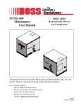
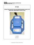
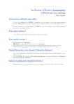
CONTROLS
ADVANTAGE AIR SINGLE VAV CONTROL SYSTEM
TYPICAL DAMPER ACTUATOR
TYPICAL ZONE CONTROLLER
TYPICAL CABLE
TYPICAL CABLE
JOINER
FEATURES
APPLICATIONS
•
•
•
•
•
•
•
•
•
•
•
•
•
Low cost.
Suitable for a limited number of VAV controls off a
central air conditioning system such as corner
offices, conference rooms, and computer rooms or
executive offices.
Provides occupant with independent, adjustable
temperature control in each zone.
Automatically adjusts the required air quantity to
maintain the required room/zone temperature.
All damper motors are pre installed and tested on
Advantage Air Exact Air fittings.
Can be used in conjunction with any make of air
conditioning, heating or evaporative unit.
Can be easily retro fitted to existing systems.
Supplied with all the necessary wiring and fittings.
The only electrical work necessary is a power point
in the ceiling.
Detects if the A/C unit is in a cooling or heating
mode and will automatically inverse operation.
Attractive simple to use digital room thermostats
with touch pad will maintain room temperature
+ - o
/ 1 C.
within
Intelligent 24Volt damper motor with quick connect
colour coded wiring does not require an electrician.
Simple commissioning eliminates the need to
balance air to zones.
•
•
Suitable for small commercial or residential,
ducted, reverse cycle, air conditioning systems.
Can be used on ducted gas heating systems.
Care should be taken to ensure there are
sufficient constant volume outlets on the system
to handle the additional air volume when the
VAV zone(s) are fully closed.
DIMENSIONS
25 O/A
TYPICAL CABLES
73 O/A
TYPICAL ZONE
CONTROLLER
115 O/A
CABLE
LENGTH 6M,
12M OR 25M
OPTIONS
TYPICAL DAMPER ACTUATOR
88 O/A
55 O/A
136 O/A
REVISION 05/10/02
I-VAV 1 ADVANTAGE AIR SINGLE VAV
CONTROLS
ADVANTAGE AIR SINGLE VAV
INSTALLATION INSTRUCTIONS
1. Ensure the Air Conditioning system is designed,
7. Connect RED – CABLES from ZONE CONTROL-
installed and running correctly.
LER to the corresponding DAMPER ACTUATORS
2. Switch A/C unit off.
3. Locate the ZONE CONTROLLER in it’s respec-
(ROOM TEMP. SENSOR )
8.
tive zones as follows:
•
Approx 1.6 metres above the floor.
•
Not exposed to direct sunlight through
windows.
•
Not exposed to drafts or air discharge
from the A/C outlet.
•
In a position representative of the zone in
which it is installed.
•
Do not place furniture such as book
cases etc in front of the controller.
port. Observe colour coding.
Connect BLUE – CABLE (DUCT TEMP SENSOR)
to the DAMPER ACTUATOR (SUPPLY AIR TEMP SENTSOR)
port.
•
Do not locate heat generating appliances
such as computers, TV’s fridges etc under the ZONE CONTROLLER .
4. Use the ZONE CONTROLLER back plate (right
side up) as a template. Provide a 22mm cable
access hole and a minimum of 2 x 4mm mounting
holes.
5.
Install RED – CABLES in wall cavity / conduit
for each ZONE.
9.
Locate a suitable position up stream of the controlled damper for the SUPPLY AIR TEMPERATURE probe to be installed (maximum 1.5 metersfrom the DAMPER ACTUATOR ).
10. Drill one 6mm holes on the EXACTAIR. Ensure the
6.
Install back plate using the mounting screws
and plugs provided.
hole is clear of all gears or damper blades.
11. Insert the probe into the EXACTAIR and fasten the
grommet using the 4 screws supplied.
12. Provide a 3 pin power point in the ceiling space
REVISION 05/10/02
I-VAV 2 ADVANTAGE AIR SINGLE VAV
CONTROLS
ADVANTAGE AIR SINGLE VAV - INSTALLATION
INSTRUCTIONS
within 25 metres of the new VAV damper.
a. Switch A/C unit on and set temperature to cooling at 15oC.
b. Set the ZONE CONTROLLER to “15oC”
c.
Assuming the room temperatures are above
15oC, after 5 minutes, check that the following
has occurred :
•
f.
g.
13. Connect BEIGE – CABLES from DAMPER AC-
Zone should open fully.
Set all A/C unit to 30oC
Assuming the room temperatures are below
TUATOR (24V POWER SUPPLY ) port to the POWER
30oC, after 5 minutes, check that the following
SUPPLY. Do not substitute standard telephone
has occurred:
cable for the beige cable as the polarity is incor-
•
h.
rect.
Zone should close fully.
Readjust the A/C unit to required operating set
point.
14. Connect POWER SUPPLY to an RCD protected
i.
Readjust the ZONE CONTROLLER to required
operating set point.
j.
Instruct occupant in the use and limitations of
the VAV control system
k.
Handover the user manual and installation instructions to the owner.
switched sockett and switch power on.
15. By pressing the STANDBY/AUTO button the
ZONE CONTROLLER display will be changed
from “STANDBY” TO “AUTO” MODE.
16. Test the VAV as follows
STANDBY
STANDBY / AUTO BUTTON
Advantage Air
No liability
Make sure you read and understand all the installation instructions before you install this VAV system. Advantage Air (Aust) Pty Ltd does not accept
any responsibility for any loss or damage that may be caused either directly or indirectly by the installation of this VAV system.
REVISION 05/10/02
I-VAV 3 ADVANTAGE AIR SINGLE VAV
CONTROLS
ADVANCED AIR SINGLE VAV - SPECIFICATIONS
ZONE CONTROLLER
PROCESSOR:
RISC microcontroller
DIMENSION:
73(W)x115(H)x 25(D) mm
OPERATING TEMPERATURE:
0 – 45°C
THERMAL CONSTANT:
3 mins.
CONFORMITY:
C-Tick Approved
DAMPER ACTUATOR, ADM24S
PROCESSOR:
RISC microcontroller
DIMENSION:
88(W)x55(H)x 136(D) mm
OPERATING TEMPERATURE:
0 – 70°C.
CONFORMITY:
C-Tick Approved.
REVISION 05/10/02
I-VAV 4 ADVANTAGE AIR SINGLE VAV
CONTROLS
ADVANTAGE AIR SINGLE VAV CONTROL
SEQUENCES
ZONE CONTROLLER ALGORITHM
Initialisation
STAND BY
Mode of operation
AUTO
Close damper
fully
Read :
• System supply air temperature
• Zone setpoint temperature
• Zone actual temperature
Setpoint oC > Actual oC = HEAT
Setpoint oC < Actual oC = COOL
Zone requirement
Supply air oC
< Actual oC = COOL
Damper
motor drive
direction
OPEN
System supply
air temperature
Supply air oC
> Actual oC = HEAT
Supply air oC
<Actual oC = COOL
Damper
motor drive
direction
CLOSE
System supply
air temperature
Damper
motor drive
direction
CLOSE
Supply air oC
> Actual oC = HEAT
Damper
motor drive
direction
OPEN
Calculate deviation from setpoint
Room oC minus Setpoint oC
> +/- 0.1 oC & < +/- 0.6 oC
Deviation
> +/- 0.6 oC
+/- 0.1 oC
Damper motor
drive response time
SLOW
Damper
motor drive
NO response
Damper
motor drive
response
FAST
Drive damper motor
Use direction & response time
REVISION 05/10/02
I-VAV 5 ADVANTAGE AIR SINGLE VAV
CONTROLS
ADVANTAGE AIR SINGLE VAV- ORDER FORM
CONTRACTOR:________________________________________________________________________
PROJECT NAME:_______________________________________________________________________
PROJECT ADDRESS:___________________________________________________________________
PROJECT OR ORDER NUMBER:_________________________________________________________
MARK WITH AN X WHERE APPLICABLE
TOTAL NUMBER OF
VAV KITS REQUIRED
VAV
RED CABLE
BEIGE CABLE
(ZONE CONTROLLER TO DAMPER
ACTUATOR)
(DAMPER ACTUATOR TO MASTER
CONTROLLER POWER)
6M
12M
25M
6M
12M
25M
1
2
3
4
5
6
7
8
9
10
TOTAL
NUMBER OF JOINERS
REQUIRED
ARE EXACTAIR ORDER
FORMS ATTACHED
BEIGE
RED
YES
NO
NOTES:
1. CABLE FOR EACH ZONE MUST NOT EXCEED: 37 METRES PER COLOUR.
2. DO NOT EXCEED 1 JOINER PER 37 METERS OF CABLE.
3. DO NOT SUBSTITUE BEIGE CABLES WITH STANDARD TELEPHONE CABLE.
REVISION 05/10/02
I-VAV 6 ADVANTAGE AIR SINGLE VAV
CONTROLS
ADVANTAGE AIR SINGLE VAV- USER MANUAL
ZONE REQUIRES COOLING TO
ACHIEVE SETPOINT TEMPERATURE
SCREEN
COOL
23 OC
SETPOINT TEMPERATURE
STANDBY / AUTO
BUTTON
SETPOINT
TEMPERATURE UP
BUTTON
ZONE CONTROLLER SHOWN IN
AUTO MODE
SETPOINT
TEMPERATURE DOWN
BUTTON
GETTING STARTED
HOW DOES THE ADVANCED AIR CONTROL SYS-
1. Ensure A/C unit is running
TEM WORK
2. Set ZONE CONTROLLER to required temperature
The Advantage Air single VAV works by measuring
3. To switch air off to zone set ZONE CONTROLLER
the temperature in the zone (room temperature) then
to “STAND BY”.
compares the zone temperature with the setpoint and
HOW TO GET THE BEST OUT OF YOUR SYSTEM
the system supply air temperature. The VAV then
1. In summer ensure the A/C unit control is set at or
takes the necessary action to reduce or increase the
slightly below the lowest ZONE CONTROLLER set
amount of air entering the room to enable the room
point. In winter ensure the A/C unit control is set at
temperature to match the setpoint.
or slightly above the highest ZONE CONTROLLER
set point.
2. Run the system for longer periods this will enable
the ZONE CONTROLLERS to stabilise the system.
It should be noted that the VAV can only make use of
the supply air temperature being provided by the airconditioning unit. The VAV cannot provide heating
3. Keep unused zones in STANDBY.
while the A/C unit is running in a cooling mode. In the
4. Run the A/C unit fan in continuous mode. (if appli-
event that the zone requires cooling while the A/C
cable)
5. If rapid response from your system is required, adjust the ZONE CONTROLLER setpoint to its ex-
unit is in a heating mode the VAV will close of the air
supply to the zone until such time as cool supply air is
available.
treme setting. For example if you enter the zone on
a very hot day and want to cool the zone down as
quickly as possible set the ZONE CONTROLLER
setpoint to 15oC. Remember to put it back to your
normal comfort level once the zone has reached the
desired temperature.
WHAT TO DO IF ZONES ARE NOT REACHING
YOUR COMFORT LEVEL
1. Change setting on zone controller.
2. Change setting on A/C unit controller.
REVISION 05/10/02
I-VAV 7 ADVANTAGE AIR SINGLE VAV
CONTROLS
ADVANTAGE AIR SINGLE VAV - USER MANUAL
SYMPTOM
Zone too hot
Zone too cold
POSSIBLE CAUSES
REMEDY
A/C unit not running
Switch A/C unit on
A/C unit control setpoint too high
Adjust A/C unit control setpoint
down
Zone controller on standby
Switch zone controller out of stand
by and into auto mode.
Zone controller setpoint too high
Adjust zone controller setpoint down
A/C unit not running
Switch A/C unit on
A/C unit control setpoint too low
Adjust A/C unit control setpoint up
Zone controller on standby
Switch zone controller out of stand
by and into auto mode.
Adjust zone controller setpoint up
Zone controller setpoint too low
REVISION 05/10/02
I-VAV 8 ADVANTAGE AIR SINGLE VAV