1
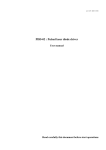
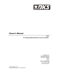
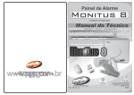
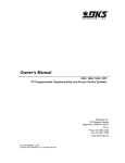
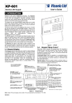
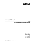
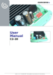
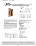
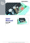
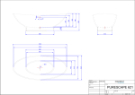
User Manual
C3CON1X
One-channel Control Box
concens control concept
Version 1.2 – December 2011
Installation
The one-channel C3CON1X control box
with wired hand control and rechargeable
NiMH battery from concens is a control
circuit with many features, which is
recommended
when
controlling
an
ac-tuator with DC motor.
The system normally consists of:
1.1) Controlbox (picture 1) with:
●● 2 pcs 6-pole connectors for motor and
handset.
●● 1 connector for the Patented
1400mAh NiMH
●● Rechargeable NiMH battery 24VDC,
1400mAh (picture 6)
1.2) Handset (picture 2) with 2 buttons
and spiral cable.
The control box is mounted by using the
U-shaped safety clip (item 1.5) delivered
with the system (pat. Appl). The bracket
is made of steel, and can be welded onto
the wanted location, or mounted by using
the holes in the bracket. The controlbox
(item 1.1) is hold in the bracket by the
strong neodymium magnets inside the
box. If the controlbox is to be mounted
in a direction where there is a risk for
falling off during mowing, then a springloaded safety clip (picture 5) is available
(optional).
The actuator and handset must be
installed by using the 6-pole (Molex
Minifit size 5556) connectors mounted
side by side. They are both wired equal
enabling flexibility in selecting the wanted
connector.
1
2
3
1.3) Charger (picture 3) 100-240VAC
1.4) Bracket (picture 4) for mounting C3
controlbox.
4
1.5) Safety clip (picture 5). To be used
if controlbox is mounted vertical or
upside down, or if strong fixation is
needed. Optional.
5
6
The handset (item 1.2) can be delivered with a hook (picture 7) or with a flat
backside (picture 8). The flat backside make the use of wall holder available
(picture 9) by utilizing the build-in neodymium magnets in the handset (pat. Appl).
Also a string can be used for holding the handset (picture 10).
7
8
9
Version 1.2 – December 2011
2
The manufacturer of this
equipment is not aware of
any harmful interference
caused by this equipment to
other equipment. However,
there is no guarantee that
interference will not occur in
particular installations and it
is recommended to test the
equipment in the actual
environment prior to putting
it into use.
10
Operation
Startup
The system is started by inserting the
battery into the circular holder in the end
of the controlbox (picture 11). Since the
battery is hold by eight strong neodymium
magnets (pat. Appl) , it will hold itself in
place with the correct position (picture
12), and a confirming BEEEEEEP is heard.
This indicates, that the connection is
made, the voltage level is accepted, and
the system can be used.
When one of the buttons on the handset
is pressed (picture 13), then the actuator
starts and is mowing until the button is
released again, or if the actuator has
reached the end of the stroke, whereby
the DC motor stalls which will let the
control circuit disconnect the voltage to the
motor, and switch on the braking system
to hold the actuator from mowing.
Features
The same will happen if the actuator
meets a resistance for mowing. The
controlbox can be programmed to have
“soft-start” of the actuator, which is
always recommended, since it gives a
more smooth movement, and this way
of starting a DC motor is avoiding the
big start current which is normal without
“soft-start”. “Soft-start” results in longer
lifetime of the motor. The controlbox is
programmed to control and protect the
actuator. It can be set to control 0-4
Ampere, or max 10 Ampere by internal
switch. The controlbox checks the battery
level every 24 seconds, and when the
battery reaches a low limit, then the
controlbox will give a double-beep every
24 seconds to indicate that the battery
needs recharging. The battery voltage
level is also checked every time the
actuator is used, and if the Voltage level
is under the pre-programmed level, then
the controlbox gives a doublebeep thereby
indicating the need for a re-commended
recharge of the battery, or exchange to
another recharged battery.
Battery
The battery is protected inside with a
thermostat which will disconnect the
connection to the outside when the inside
temperature has reached 55ºC. This
will prevent a shortcircuit or too heavy
use, from damaging the battery. The 2
poles on the end of the battery are the
negative voltage connection, and the
connector in the centre of the end of
the battery is the positive connection.
Handling of batteries
Insert battery: Clean the magnetic poles
for all dirt or metal chips. Push the
battery into the C3 housing, turn it right
or left until it is being pulled into the right
position by the magnets in the end of that
battery. The C3-controller is confirming
connection with a BEEEEEEEEP. Remove
battery: Turn the battery 90 degrees
(right- or left) - the battery will be
”pushed out” due to the magnets at the
top end of the battery. Keep the battery
poles free of dirt and metal chips.
Charging battery: Shall be done in
the ”C3-charger”, full re-charging
takes 5-8 hours, depending on state
of charge. The battery (NiMH-type)
can be recharged from any state of
charge without reducing battery life
or battery-capacity.
When connecting the ”C3-charger” to the
mains (100 – 240 V AC), the red diode
lights up continuously and a single flash
in the green diode appear before it turns
off again. When inserting the battery
into the charger, the green diode starts
flashing with an interval of 1/sec during
the charging process.
When charging is finishing, the green diode
stops flashing and turns on continuously,
the battery is fully charged, can be
removed and is ready for use in the C3
controller. Repeated runs at a high rate
with heavy loads, may create overheating
inside the battery – a safety interlocktemperature sensor will disconnect the
power. When the battery has cooled down
to accepted working temperature the
power switch on automatically.
The battery ”is pulled-into” the C3housing by heavy magnets. Take care
with dirt, such as metallic particles and
other small magnetic parts ! – in serious
cases it may prevent electrical contact
and the C3-controller / C3 charger shall to
be returned for repair. Always - check for
dirt on the battery poles before inserting
it into the C3-controller ! Batteries not
used: To secure long lifetime of NiMH
batteries, we recommend to recharge the
battery at least every 3 months.
Do not dispose batteries in the
ordinary household waste.
Some communities offer recycling
or collection of batteries —
contact your local government for
disposal practices in your area.
11
12
13
Beep signals:
BEEEEEEEP: Power on (battery inserted)
BEEP..BEEP: Every 24 seconds (when the system is not in use): = indicating low battery level, please recharge.
BEEP..BEEP: When starting the actuator = low voltage, please change battery soon, or recharge—the battery will still give power,
but only limited time.
BEEEEEEEP: When running the actuator = battery lower than 17,6Volt (only down/in movement will be accepted thereafter)
BEEP..BEEP..BEEP..BEEP (Temperature inside control box too high, please take a break)
Version 1.2 – December 2011
3
Specifications
C3 System
Components
1. Control box (491 grams)
2. Hand control (93 grams)
Standard cable length 75 cm
(200 cm stretched)
3. Battery charger box (500 grams)
4. Bracket (318 grams)
5. Battery (573 grams)
1
2
Black (RAL 9005) is standard
colour and beige (Pantone 454)
foil on remote control
3
Foil design can be adapted to
customer requirements.
Fuse: T 5A located inside connector end. To be exchanged using T10 screwdriver.
Dimensions
Type
Power supply
Maximum continuous current
Capacity
Low-capacity warning
NiMH
24 V DC
7 A (Short-time peak current 10 - 20 A)
1400 mAh
Sound signal
54.5
40
156.2
7
5
91.5
Battery
Ø51.8
Battery
4
3.5
123
40
Battery
Attention, consult
45
Ø51.8
142
Hand control
ACCOMPANYING DOCUMENTS
- If faults are observed, the product must be replaced or returned to manufacturer for repair.
- If the C3 controller for some reason is not being used for a few days remove battery from the C3 controller
to protect the battery against deep discharge and permanent damage.
- Cleaning of product can be done using a damp cloth.
Version 1.2 – December 2011
4