1
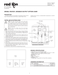
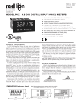
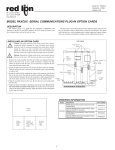
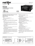
Bulletin No. PAXCDC5-C Drawing No. LP0549 Released 11/08 Tel +1 (717) 767-6511 Fax +1 (717) 764-0839 www.redlion.net MODEL PAXCDC - PROFIBUS-DP COMMUNICATIONS OPTION CARD ! CONNECTS PAX METER TO PROFIBUS-DP NETWORK ! STANDARD 9-PIN D-SUB CONNECTOR INTERFACE ! CYCLIC I/O DATA TRANSMISSION, UP TO 84 BYTES IN/OUT ! OPERATING RANGE FROM 9.6 KBAUD TO 12 MBAUD WITH AUTOMATIC BAUD RATE DETECTION ! STATION ADDRESS SET THROUGH ROTARY SWITCHES ! CONFIGURATION VIA SELECTION OF PRE-CONFIGURED MODULES FOR ANALOG OR DIGITAL PAX METER TYPE ! FREEZE MODE AND SYNC MODE SUPPORTED ! DIAGNOSTIC LEDs INDICATE CARD STATUS ! PNO CERTIFIED, CONFORMANCE TESTED SLAVE DEVICE DESCRIPTION The PAX PROFIBUS-DP Communications Option Card provides a direct connection for a PAX panel meter to a PROFIBUS-DP Network. This allows a PROFIBUS Master device, such as a PLC, to control and monitor the operation of the PAX meter. The meter functions as an intelligent PROFIBUS-DP Slave device on the Network. The PROFIBUS-DP Network connects through a 9-pin D-subminiature female connector on the rear of the card. The card is installed in the PAX meter using a slotted rear cover, allowing the PROFIBUS-DP Connector to extend beyond the rear of the PAX case. Power for the card is provided internally from the power supply of the PAX meter. The PROFIBUS-DP Network is isolated from the control electronics on the card using high-speed optocouplers. This fully featured communications card supports Automatic Baud Rate Detection, with an operating range of 9.6 Kbaud up to 12 Mbaud. The Station Address is set via rotary switches. The card’s address is read at power up. Data Exchange with the Master device occurs through cyclic I/O data transmission. The size of the I/O data block is determined by the selection of pre-configured Modules for Analog or Digital PAX meter type. All data values are in 32-bit integer format, Motorola byte ordering. The PROFIBUS-DP protocol per EN 50170 is implemented using the Siemens SPC3 ASIC. Three on-board Diagnostic LEDs indicate the status of Data Exchange (DATA), the SPC3 Watchdog (WD) and DP State Machine (DP). PNO Conformance and GSD File The PAX PROFIBUS-DP Card is PNO certified, having passed the conformance test for PROFIBUS-DP Slave devices, Certificate No. Z01170. The PNO Identifier for this PROFIBUS device is 0x09D0. The functional characteristics are described in GSD file REDL09D0.GSD. The GSD file and PAX bitmap can be downloaded from the Red Lion Controls website. SPECIFICATIONS 1. FIELDBUS TYPE: PROFIBUS-DP per standard EN 50170, implemented with Siemens SPC3 ASIC 2. BUS INTERFACE: Isolated RS485 through 9-Pin D-Sub connector 3. NETWORK ISOLATION: 500 Vrms for 1 minute (50 V working) between PROFIBUS-DP network and PAX Sensor & User Input commons. Not isolated from other PAX option card commons. 4. POWER: Card powered internally by the PAX meter 5. OUTPUT POWER: +5 VDC @ 90 mA max. available on the D-Sub connector pins 5 (GND) and 6 (+5 V) 6. BAUD RATES: 9.6 Kbaud to 12 Mbaud, Auto Baud Rate Detection 7. STATION ADDRESS: 0 to 125, set by rotary switches 8. SUPPORTED FUNCTIONS: FREEZE Mode: Supported SYNC Mode: Supported FAIL SAFE Mode: Not Supported EXTERNAL DIAGNOSTIC DATA: Not Supported 9. INSTALLATION REQUIREMENTS: Installed Depth: 4.88" (124 mm) from the rear of the PAX bezel Additional Height: 0.35" (9 mm) above the PAX case surface ORDERING INFORMATION MODEL NO. DESCRIPTION PAXCDC 1 PAX PROFIBUS-DP Communications Card PART NUMBER PAXCDC50 INSTALLING AN OPTION CARD TOP VIEW Caution: The option and main circuit cards contain static sensitive components. Before handling the cards, discharge static charges from your body by touching a grounded bare metal object. Ideally, handle the cards at a static controlled clean workstation. Also, only handle the cards by the edges. Dirt, oil or other contaminants that may contact the cards can adversely affect circuit operation. Warning: Exposed line voltage exists on the circuit boards. Remove all power to the meter AND load circuits before accessing the unit. 1. Remove the main assembly from the rear of the case. Squeeze the finger holds on the rear cover, or use a small screwdriver to depress the side latches to release it from the case. It is not necessary to separate the rear cover from the main circuit card. 2. Locate the option card connector for the serial communication card. Hold the unit by the rear cover, not the display board, when installing an option card. 3. Install the option card by aligning the option card with the slot in the rear cover. Be sure the connector is fully engaged and the tab on the option card rests in the alignment slot on the display board. 4. Slide the assembly back into the case. Be sure the rear cover latches fully into the case. PRINCIPLE OF OPERATION DIAGNOSTIC LEDs The PAX PROFIBUS-DP Card provides the PROFIBUS Network with access to an Input Data Block (data written to the PROFIBUS Network from the PAX) and an Output Data Block (data read from the PROFIBUS Network by the PAX). Using an internal high speed protocol, the card scans each PAX register in turn, continuously reading Input Data and only writing Output Data on demand. The PAX registers are mapped into each Input and Output Data Block, allowing the PROFIBUS Network read/write access to all the registers in the PAX. The structure of these Data Blocks is described in more detail in section Data Block Structure. The Input Data and Output Data Blocks are updated at the end of each scan of the host PAX Meter. In order to increase the rate that new data is made available to the PROFIBUS Network, a scheme is employed that reduces the number of registers polled by the card in each scan to only those that are required in the application. This Polled Read Mask maps each bit to a PAX register index which, when set, will force that register to be read from the PAX Meter. This Polled Read Mask is defined as User Parameter Data and is described in more detail in section Parameterization. Due to the cyclic nature of data exchange in the PROFIBUS network changing Output Data in a slave device, a scheme is employed that indicates which registers need to be written to the PAX Meter. This Demand Write Mask maps each bit to a register index which when set, will perform a “once only” write from the Output Data Block to the PAX Meter. Clearing and re-setting the bit in the Demand Write Mask will cause the value to be written again. The Demand Write Mask is part of the Data Block structure and is described in detail in section Demand Write and Store Request Masks. Three LEDs indicate the status of the SPC3 DP Control State Machine (DP), the Watchdog State Machine (WD) and the PROFIBUS-DP Data Exchange State (DATA) as shown in Table 1. The LEDs are viewable through the vents on the top of the PAX case. Table 1 - LED Indication of PROFIBUS-DP Card Status LED STATE STATION ADDRESS The station address is set using three rotary switches allowing the ID to be set in standard decimal notation (e.g. address = 123 - SWC = 1, SWB = 2, SWA = 3). Valid addresses range from 0 to 125. If an address greater than 125 is set, the card will default to a station address of 125. Note: The card will not default to 125 if set for 999, this number is a special test mode. 2 CARD STATUS DP (Red) WD (Green) DATA (Red) FLASHING FLASHING OFF Bus Not Connected OFF FLASHING OFF Baud Rate Search OFF ON OFF Baud Control FLASHING ON OFF Waiting for Parameterization ON ON OFF Waiting for Configuration OFF OFF ON Data Exchange PARAMETERIZATION DATA EXCHANGE The Polled Read Mask defines which PAX registers will be polled by the card and therefore updated in the Input Data Block. The Polled Read Mask is a 32bit integer with each bit mapped to a PAX register index. The Polled Read Mask is configured in the card by the Master sending a Parameterization telegram with 4 bytes of User Parameter Data representing the Polled Read Mask, in Motorola byte ordering. Table 2 shows the User Parameter bytes representing the Polled Read Mask and gives the default value and a typical example. The default Polled Read Mask indicates PAX register index 0 will be updated in the Input Block. The example Polled Read Mask indicates that PAX registers 0 and 8 will be updated in the Input Block. Table 2 - User Parameter Data Demand Write and Store Request Masks BYTE 0 DESCRIPTION - 1 2 3 4 The Demand Write Mask defines how data is written to the PAX. The Demand Write Mask is a 32-bit integer with each bit mapped to a PAX register index. Setting a bit in the Demand Write Mask of the Output Data Block will force the corresponding register to be written “once only” to the PAX. Clearing and re-setting the bit will cause the value to be written again. The Demand Write Mask is part of the Data Block structure. The Write Service Status register in the Input Data Block reports when the register has been written to the PAX by setting the corresponding bit. By monitoring this register a PLC program can detect when the Output Data has been serviced. The bit will be cleared in the Service Status register when the corresponding bit is cleared in the Demand Write Mask. The Store Mask defines how the written value is to be stored in the PAX. The PAX meters have some values stored in EEPROM so they may power up in the last saved state. For values that change often it is possible to exceed the life of an EEPROM with repeated writes to the same address location - this method inhibits writes to EEPROM. The Store Mask is a 32-bit integer with each bit mapped to a PAX register index. Setting a bit will inhibit the corresponding register from being saved to EEPROM. Polled Read Mask DEFAULT 0x00 0x00 0x00 0x00 0x01 EXAMPLE 0x00 0x00 0x00 0x01 0x01 CONFIGURATION Data Block Structure The 2 basic PAX meter types are the Analog PAX (5-digit units) and the Digital PAX (6-digit units). They differ in the number of registers available and therefore the size of the Data Block required to map all the registers completely. Each PAX register is represented as a 32-bit Integer requiring 2, 16-bit words or 4 bytes. Configuration of the Data Block is by the selection of pre-configured modules, identified in the GSD file as “PAX Digital (6-digit)” and “PAX Analog (5-digit)”, that correspond to the host PAX Meter type. Table 3 shows the Data Block Structure, consisting of the Write and Store Masks and the individual PAX Data Registers. Each Data Register value is a 32bit Integer, with Motorola byte ordering. For the Analog PAX meters, the Data Block size is 48 bytes Input, 48 bytes Output. For the PAXDP and the Digital PAX meters, the Data Block size is 84 bytes Input, 84 bytes Output. Table 3 - Data Block Structure PAX ANALOG INPUT METER (5-Digit) PAXDP ANALOG INPUT METER (5-Digit) PAXI DIGITAL COUNT / RATE (6-Digit) PAXCK DIGITAL CLOCK / TIMER (6-Digit) REGISTER INDEX (Mask Bit) DATA BLOCK BYTES - 1-4 - 5-8 0 9 - 12 Input * Input A (relative) * Count A Timer 1 13 - 16 Total * Input B (relative) * Count B Counter 2 17 - 20 Max. Input * Calculation * Count C RTC Time 3 21 - 24 Min. Input * Total * Rate RTC Date 4 25 - 28 Setpoint 1 Min Input * Min. Rate Setpoint 1 5 29 - 32 Setpoint 2 Max Input * Max. Rate Setpoint 2 6 33 - 36 Setpoint 3 Input A (absolute) * Scale Factor A Setpoint 3 7 37 - 40 Setpoint 4 Input B (absolute) * Scale Factor B Setpoint 4 8 41 - 44 AOR ** Input A (offset) Scale Factor C Setpoint Off 1 Demand Write Mask (Output) / Service Status (Input) Store Mask (Output) / Unused (Input) 9 45 - 48 CSR ** Input B (offset) Count Load A Setpoint Off 2 10 49 -52 ---- *** Count Load B Setpoint Off 3 11 53 - 56 ---- *** Count Load C Setpoint Off 4 12 57 - 60 ---- Setpoint 1 Setpoint 1 Timer Start 13 61 - 64 ---- Setpoint 2 Setpoint 2 Counter Start 14 65 - 68 ---- Setpoint 3 Setpoint 3 Timer Stop 15 69 - 72 ---- Setpoint 4 Setpoint 4 Counter Stop 16 73 - 76 ---- MMR ** MMR ** MMR ** 17 77 - 80 ---- AOR ** AOR ** RTC Day 18 81 - 84 ---- SOR ** SOR ** SOR ** * Indicates Read-Only parameters. All other parameters are Read/Write. ** Indicates PAX Manual Mode Registers. See next section for description. *** Indicates bit value must not be set in the Parameterization polled read masks. 3 PAX MANUAL MODE REGISTERS CSR - Control Status Register (PAX Analog Only) (AOR) Analog Output Register (Not applicable to PAXCK) The Control Status Register is used to directly control the meter’s outputs (setpoints and analog output), or view the state of the setpoint outputs and the status of the temperature sensor (PAXT only). The CSR register is bit mapped, with the bit positions of the least-significant byte assigned to specific control functions. The control functions are invoked by writing to the appropriate bit position. The bit position definitions are: The Analog Output Register value defines the signal level of the meter’s analog output. The range of values for this register is 0 to 4095 (0FFFh), which corresponds to the analog output signal ranges shown in Table 4. bit 0: Setpoint 1 Output 0 = output off bit 1: Setpoint 2 Output 1 = output on bit 2: Setpoint 3 Output bit 3: Setpoint 4 Output bit 4: Auto/Manual Mode 0 = automatic mode 1 = manual mode bit 5: Unused (always stays 0) bit 6: Sensor Status (PAXT only) 0 = sensor normal 1 = sensor fail bit 7: Unused (always stays 0) Setting bit 4 of the CSR selects Manual Mode. In this mode, the setpoint outputs are defined by the values written to bits b0, b1, b2, b3; and the analog output is defined by the value written to the Analog Output Register (AOR). Internal control of these outputs is then overridden. In Automatic Mode, the setpoint outputs can only be Reset off. The contents of the CSR may be read to interrogate the state of the setpoint outputs and to check the status of the temperature sensor (PAXT only). Table 4 - Analog Output Signal Ranges Output Signal* Register Value 0-20 mA 4-20 mA 0 0.000 4.000 0.000 1 0.005 4.004 0.0025 2047 10.000 12.000 5.000 4094 4095 19.995 20.000 19.996 20.000 9.9975 10.000 0-10 V *Due to the absolute accuracy rating and resolution of the output card, the actual output signal may differ 0.15% FS from the table values. The output signal corresponds to the range selected (0-20 mA or 0-10 V). In Automatic mode, the meter controls the analog output signal level. Reading the AOR will show the present value of the analog output signal. While in Automatic mode, this register may be written to, but it has no effect until the analog output is placed in the Manual mode. In Manual mode, writing to the AOR causes the analog output signal level to update per the value written. Manual mode is engaged by setting bit 4 of the CSR (PAX Analog meter) or bit 0 of the MMR (PAXDP/PAXI). If a value larger than 4095 is written to the AOR, 4095 will be loaded. MMR - Auto/Manual Mode Register (PAXDP/PAXI/PAXCK) This register sets the controlling mode for each output in the PAX meters. Each output may be independently changed to Auto or Manual mode. The MMR register is bit mapped, with the bit positions of the least-significant byte assigned to specific outputs. Auto or Manual mode is selected by writing to the appropriate bit position. The bit position definitions are: PAXDP/PAXI PAXCK bit 0: Analog Output bit 1: Setpoint 4 Output bit 2: Setpoint 3 Output bit 3: Setpoint 2 Output bit 4: Setpoint 1 Output bit 0: Setpoint 4 Output bit 1: Setpoint 3 Output bit 2: Setpoint 2 Output bit 3: Setpoint 1 Output INSTALLATION AND CONNECTION Installation Clearance Required - In Inches (mm) 0 = Auto Mode, 1 = Manual Mode In Auto Mode (0) the meter controls the setpoint output state and the Analog Output (PAXDP/PAXI only). In Manual Mode (1) the setpoint outputs are defined by the value in the Setpoint Output Register (SOR); and the Analog Output is defined by the value written to the Analog Output Register (AOR). When transferring from Auto Mode to Manual Mode, the meter holds the last output value (until the register is changed by a write). SOR - Setpoint Output Register (PAXDP/PAXI/PAXCK) The Setpoint Output Register is used to view or change the states of the setpoint outputs in the PAX meters. Reading this register will show the present state of all the setpoint outputs. A “0” means the output is inactive and a “1” means the output is active. In Auto Mode (see MMR description), the meter controls the setpoint output state. In Manual Mode, the four least-significant bits of the SOR are assigned to specific outputs. Writing to the appropriate bit position defines the state of the setpoint output. The bit position definitions are: bit 0: Setpoint 4 Output Status bit 1: Setpoint 3 Output Status bit 2: Setpoint 2 Output Status bit 3: Setpoint 1 Output Status PROFIBUS-DP Network Connection PROFIBUS plug connectors such as Siemens 6ES7 972-0BA10-0XA0 are recommended. When wiring the connector, be sure to observe the proper direction for data flows, indicated by the arrows on the connector. When the PAX meter is the last device on the network, set the terminating resistor switch on the connector to the “ON” position. 0 = Output Off 1 = Output On Red Lion Controls AP Red Lion Controls 20 Willow Springs Circle Red Lion Controls BV Printerweg 10 Unit 101, XinAn Plaza Building 13, No.99 Tianzhou Road York PA 17406 NL - 3821 AD Amersfoort Tel +1 (717) 767-6511 Tel +31 (0) 334 723 225 Tel +86 21 6113-3688 Fax +1 (717) 764-0839 Fax +31 (0) 334 893 793 Fax +86 21 6113-3683 ShangHai, P.R. China 200223