1
TECHNICAL & SERVICE MANUAL
SAP–K186ST
SAP–K256ST
+ SAP–C186ST
+ SAP–C256ST
FILE NO.
SPLIT SYSTEM AIR CONDITIONER
Indoor Model No. Product Code No.
Destination
Outdoor Model No. Product Code No.
Destination
SAP– K186ST
1 852 347 24
Asia / Russia (50Hz)
SAP – C186ST
1 852 347 26
Asia / Russia (50Hz)
SAP– K256ST
1 852 347 25
Asia / Russia (50Hz)
SAP – C256ST
1 852 347 27
Asia / Russia (50Hz)
Indoor Unit
Outdoor Unit
SAP – K186ST
SAP – C186ST
SAP – C256ST
SAP – K256ST
REFERENCE NO.
SMXXXXXX
,PSRUWDQW
3OHDVH5HDG%HIRUH6WDUWLQJ
:KHQ7UDQVSRUWLQJ
Be careful when picking up and moving the indoor and
outdoor units. Get a partner to help, and bend your
knees when lifting to reduce strain on your back. Sharp
edges or thin aluminum fins on the air conditioner can
cut your fingers.
This air conditioning system meets strict safety and
operating standards. As the installer or service person,
it is an important part of your job to install or service the
system so it operates safely and efficiently.
:KHQ,QVWDOOLQJd
)RU VDIH LQVWDOODWLRQDQGWURXEOHIUHHRSHUDWLRQ\RX
PXVW
d,QD&HLOLQJRU:DOO
Make sure the ceiling/wall is strong enough to hold the
units weight. It may be necessary to construct a strong
wood or metal frame to provide added support.
ƽCarefully read this instruction booklet before
beginning.
ƽFollow each installation or repair step exactly as
shown.
d,QD5RRP
Properly insulate any tubing run inside a room to
prevent “sweating” that can cause dripping and water
damage to walls and floors.
ƽObserve all local, state, and national electrical codes.
ƽPay close attention to all warning and caution notices
given in this manual.
:$51,1*
&$87,21
d,Q0RLVWRU8QHYHQ/RFDWLRQV
Use a raised concrete pad or concrete blocks to
provide a solid, level foundation for the outdoor unit.
This prevents water damage and abnormal vibration.
7KLV V\PEROUHIHUVWRDKD]DUGRU
XQVDIHSUDFWLFHZKLFKFDQUHVXOW
LQ VHYHUHSHUVRQDO LQMXU\RU
GHDWK
d,QDQ$UHDZLWK+LJK:LQGV
Securely anchor the outdoor unit down with bolts and a
metal frame. Provide a suitable air baffle.
7KLV V\PEROUHIHUVWRDKD]DUGRU
XQVDIHSUDFWLFHZKLFKFDQUHVXOW
LQSHUVRQDO LQMXU\RUSURGXFWRU
SURSHUW\GDPDJH
d,QD6QRZ\$UHDIRU+HDW3XPSW\SH6\VWHPV
Install the outdoor unit on a raised platform that is
higher than drifting snow. Provide snow vents.
,I1HFHVVDU\*HW+HOS
:KHQ&RQQHFWLQJ5HIULJHUDQW7XELQJ
These instructions are all you need for most installation
sites and maintenance conditions. If you require help
for a special problem, contact our sales/service outlet
or your certified dealer for additional instructions.
• Use the flare method for connecting tubing.
• Apply refrigerant lubricant to the matching surfaces
of the flare and union tubes before connecting them,
then tighten the nut with a torque wrench for a leakfree connection.
,Q&DVHRI,PSURSHU,QVWDOODWLRQ
The manufacturer shall in no way be responsible for
improper installation or maintenance service, including
failure to follow the instructions in this document.
• Check carefully for leaks before starting the test run.
:KHQ 6HUYLFLQJ
6SHFLDO3UHFDXWLRQV
:$51,1*
• Turn the power off at the main power box (mains)
before opening the unit to check or repair electrical
parts and wiring.
:KHQ:LULQJ
(/(&75,&$/ 6+2&.&$1&$86(
6(9(5(3(5621$/,1-85<25
'($7+21/<$48$/,),('
(;3(5,(1&('(/(&75,&,$16+28/'
$77(03772:,5(7+,6 6<67(0
• Do not supply power to the unit until all wiring and
tubing are completed or reconnected and checked.
• Highly dangerous electrical voltages are used in this
system. Carefully refer to the wiring diagram and
these instructions when wiring. Improper connections
and inadequate grounding can cause accidental
injury or death.
• Ground the unit following local electrical codes.
• Connect all wiring tightly. Loose wiring may cause
overheating at connection points and a possible fire
hazard.
Ɣ Install a protective leakage breaker depending on
the installation location (especially a damp or humid
location.)
If a leakage breaker is not installed, HOHFWULFVKRFN
• Keep your fingers and clothing away from any
moving parts.
• Clean up the site after you finish, remembering to
check that no metal scraps or bits of wiring have
been left inside the unit being serviced.
2WKHUV
&$87,21
• Ventilate any enclosed areas when installing or
testing the refrigeration system. Escaped refrigerant
gas, on contact with fire or heat, can produce
dangerously toxic gas.
• Confirm upon completing installation that no
refrigerant gas is leaking. If escaped gas comes in
contact with a stove, gas water heater, electric room
heater or other heat source, it can produce
dangerously toxic gas.
FDQRFFDU
Table of Contents
Page
1. OPERATING RANGE .............................................................................................................................. 4
2. SPECIFICATIONS
2-1. Unit Specifications .......................................................................................................................... 5
2-2. Major Component Specifications ..................................................................................................... 7
2-3. Other Component Specifications .................................................................................................... 11
3. DIMENSIONAL DATA .............................................................................................................................. 12
4. REFRIGERANT FLOW DIAGRAM ......................................................................................................... 15
5. PERFORMANCE DATA
5-1. Performance charts ....................................................................................................................... 16
5-2. Air Throw Distance Chart .............................................................................................................. 17
6. ELECTRICAL DATA
6-1. Electrical Characteristics ................................................................................................................ 18
6-2. Electric Wiring Diagrams ................................................................................................................ 19
7. INSTALLATION INSTRUCTIONS
7-1. Installation Site Selection ............................................................................................................... 22
7-2. Remote Control Unit Installation Position ....................................................................................... 24
7-3. Recommended Wire Length and Diameter ................................................................................... 25
8. FUNCTION
8-1. Room Temperature
a
Control ........................................................................................................... 26
8-2. Dry Operaion ................................................................................................................................ 27
8-3. Freeze Prevention ......................................................................................................................... 27
9. TROUBLESHOOTING
9-1. Check before and after troubleshooting ........................................................................................ 28
9-2. Air conditioner does not operate .................................................................................................... 29
9-3. Some part of air conditioner does not operate .............................................................................. 33
9-4. Air conditioner operates, but abnormalities are observed ............................................................. 35
10. CHECKING ELECTRICAL COMPONENTS
10-1. Measurement of Insulation Resistance .......................................................................................... 36
10-2. Checking Continuity of Fuse on PCB Ass’y .................................................................................... 37
10-3. Checking Motor Capacitor ............................................................................................................. 37
11. MAINTENANCE
11-1. Change of Address of Remote Control Unit in Indoor Unit ............................................................ 38
APPENDIX
................................................................................................................................................. 39
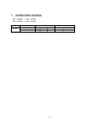
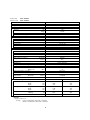
1. OPERATING RANGE
SAP – K186ST
SAP – K256ST
+ SAP – C186ST
+ SAP – C256ST
Temperature
Cooling
Indoor Air Intake Temp.
Outdoor Air Intake Temp.
Maximum
32
D.B. / 23
W.B.
48
D.B.
Minimum
19
D.B. / 14
W.B.
19
D.B.
4
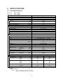
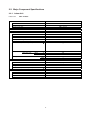
2. SPECIFICATIONS
2-1. Unit Specifications
Indoor Unit
Outdoor Unit
SAP – K186ST
SAP – C256ST
Power Source
220–240V Single phase 50Hz
Voltage rating
220/230/240 V
Performance
Cooling
Capacity
kW
BTU / h
Air circulation (High)
Moisture removal (High)
m3/h
Liters/h
5.30
18,100
–
2.3
Electrical Rating
Cooling
Available voltage range
Running amperes
P ower input
Power factor
C.O.P.
Compressor locked rotor amperes
V
A
W
%
W/W
A
198 ~ 264
8.9 / 9.3 / 10.1
1,860 / 1,950 / 2,080
95 / 91 / 86
2.85 / 2.72 / 2.55
43.0
Features
Controls / Temperature control
Control unit
Timer
Fan speeds
Airflow direction (Indoor)
Microprocessor / I.C. thermistor
Wirele ss remote controller
24-hours ON or OFF / 1-hour OFF
3 and Auto / 1 (Hi)
Manual
Auto
Washable, Anti-Mold
Rotary (Hermetic)
R22 / 1,200
Capillary tube
43
55
Flare type
5
6.35(1/4)
12.7(1/2)
Op t i o na l / A i r Cl ean F i lt e r
Indoor / Outdoor
Horizontal
Vertical
Air filter
Compressor
Refrigerant / Amount charged at shipment
Refrigerant control
Operation sound
Indoor: Hi
Outdoor: Hi
Refrigerant tubing connections
Max. allowable tubing length at shipment
Refrigerant
Narrow tube
tube diameter
W i d e t u be
R e f r i g e r a n t t u be k i t / A c c e s s or i es
g
dB-A
dB-A
m
mm (in.)
mm (in.)
Dimensions & Weight
Unit dimensions
Package dimensions
Weight
Shipping volume
Height
Width
Depth
Height
Width
Depth
Net
Shipping
mm
mm
mm
mm
mm
mm
kg
kg
m3
Remarks:
Rating conditions are:
Cooling : Indoor air temperature 27°C D.B. / 19°C W.B.
Outdoor air temperature 35°C D.B. / 24°C W.B.
5
Indoor Unit
Outdoor Unit
295
799
227
284
871
343
10.0
12.0
0.08
589
790
285
650
920
385
46.0
49.0
0.23
DATA SUBJECT TO CHANGE WITHOUT NOTICE.
Indoor Unit
Outdoor Unit
SAP – K256ST
SAP – C256ST
Power Source
220-240 V Single phase 50Hz
Voltage rating
220/230/240 V
Performance
Cooling
Capacity
kW
BTU/h
7.05
24,100
ˉ
3.3
m3/h
Liters/h
Air circulation (High)
Moisture removal (High)
Electrical Rating
Cooling
Available voltage range
Running amperes
Power input
Power factor
C.O.P.
Compressor locked rotor amperes
V
A
W
%
W/W
A
198 ~ 264
12.4 / 12.6 / 12.8
2,600 / 2,660 / 2,730
95 / 92 / 89
2.71 / 2.65 / 2.58
66.0
Features
Controls / Temperature control
Control unit
Timer
Fan speeds
Airflow direction (Indoor)
Microprocessor / I.C. thermister
Wireless remote controller
24-hours ON or OFF / 1-hour OFF
3 and Auto /1 (Hi)
Manual
Auto
Washable, Anti-Mold
Rotary (Hermetic)
R22 / 1,550
Capillary tube
45
57
Flare type
7.5
6.35(1/4)
15.88(5/8)
O pt i o n al / A i r C l e an F i lt er
Indoor / Outdoor
Horizontal
Vertical
Air filter
Compressor
Refrigerant / Amount charged at shipment
Refrigerant control
Operation sound
Indoor: Hi
Outdoor: Hi
Refrigerant tubing connections
Max. allowable tubing length at shipment
Refrigerant
Narrow tube
tube diameter
W i d e t u be
Re f r i g er a n t t ube k i t / A c c esso r ie s
g
dB-A
dB-A
m
mm (in.)
mm (in.)
Dimensions & Weight
Unit dimensions
Package dimensions
Weight
Shipping volume
Height
Width
Depth
Height
Width
Depth
Net
Shipping
mm
mm
mm
mm
mm
mm
kg
kg
m3
Remarks:
Rating conditions are:
Cooling : Indoor air temperature 27°C D.B. / 19°C W.B.
Outdoor air temperature 35°C D.B. / 24°C W.B.
6
Indoor Unit
Outdoor Unit
298
1,065
235
302
1,140
379
13.0
16.0
0.13
569
790
285
635
920
385
56.0
59.0
0.23
DATA SUBJECT TO CHANGE WITHOUT NOTICE.
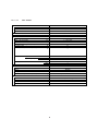
2-2. Major Component Specifications
2-2-1. Indoor Unit
Indoor Unit
SAP – K186ST
Controller PCB
Part No.
Controls
Control circuit fuse
POW-K96S-A1
Microprocessor
250 V 3.15 A
Remote Control Unit
RCS-4MVPS4EX
Fan & Fan Motor
Type
Q'ty ... Dia. and length
Fan motor model ... Q'ty
No. of poles ... Rough measure rpm
Nominal output
Coil resistance (Ambient temp. 20°C)
Safety devices
Type
Operating temp.
Run capacitor
Cross-flow
1 ... ø100 / L637
SIC-37CVL-D847-2A ... 1
8 ... 1260
47
—
—
mm
W
Open
Close
Thermal fuse
120
—
—
—
°C
μF
VAC
Flap Motor
Type
Model
Rating
Coil resistance (Ambient temp. 25°C)
Stepping motor
24BYJ48-916
DC 12 V
E a c h p a i r o f t e r m i n a l s : 2 0 0 ± 7%
Heat Exch. Coil
Coil
Rows
Fin pitch
Face area
Aluminu m plate fin / Co pp er tube
2
1.3
0.285
mm
m2
DATA SUBJECT TO CHANGE WITHOUT NOTICE.
7
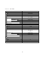
Indoor Unit
SAP – K256ST
Controller PCB
Part No.
Controls
Control circuit fuse
POW-K256M-A1
Microprocessor
250 V 3.15 A
Remote Control Unit
RCS-4MVPS4EX
Fan & Fan Motor
Type
Q'ty ... Dia. and length
Fan motor model ... Q'ty
N o . o f p o l e s . . . R o u g h m e as u r e r p m
Nominal output
Coil resistance (Ambient temp. 20°C)
Safety devices
Type
Operating temp.
Run capacitor
Cross-flow
1 ... ø94 / L845
SIC-39CVL-D847-2-A ... 1
8 ... 1305
47
—
—
mm
W
Open
Close
Internal controller
120
°C
—
—
—
μF
VAC
Flap Motor
Type
Model
Rating
Coil resistance (Ambient temp. 25°C)
Stepping motor
MP24Z3
DC 12 V
Each pair of terminals : 400 ± 7%
Heat Exch. Coil
Coil
Rows
Fin pitch
Face area
Aluminum plate fin / Co pper tube
2
1.3
0.285
mm
m2
DATA SUBJECT TO CHANGE
8
WITHOUT NOTICE.
2XWGRRU8QLW
Outdoor Unit
6$3 n &67
&RQWUROOHU 3&%
—
&RPSUHVVRU
Type
Compressor model
Nominal output
Compressor oil ... Amount
Coil resistance (Ambient temp. 20°C)
Safety devices
Rotary (Hermetic)
2V34S225AUA...85204526356
450
ATMOS NM56M, SUNISO 4GDID or equivalent ... 650
C–R : 1.572
C–S : 2.637
Internal
—
—
W
cc
Type
Overload relay
Operating temp.
Open
°C
Close
°C
Operating amp.(Ambient temp. 25°C)
Run capacitor
μF
VAC
Crank case heater
—
Trip in 6 to 16 sec.at 15A
50
400
—
)DQ )DQ 0RWRU
Type
Q'ty ... Dia.
Fan motor model ... Q'ty
N o. of pol e s . .. R ough m e a su re rp m (Hi g h )
Nomi nal output
Coil resistance (Ambient temp. 20°C)
Safety devices
Run capacitor
Type
Operating temp.
Open
Close
Propeller
1 ... ø420
KFG4-Z94A5P R ... 1
4 ... 1,000
64.2
WHT - BRN : 60.8
YEL - RED : 42.5
W
Thermal protector
135±5
Automatic reclosing
4.0
440
°C
μF
VAC
+HDW ([FK &RLO
Coil
Rows
Fin pitch
Face area
Aluminu m plate fin / Copper tube
2
1.4
0.303
mm
m2
([WHUQDO )LQLVK
Acrylic baked-on enamel finish
DATA SUBJECT TO CHANGE WITHOUT NOTICE.
Outdoor Unit
6$3 n &67
&RQWUROOHU 3&%
—
&RPSUHVVRU
Type
Compre ssor mo del
Nominal output
Compressor oil ... Amount
Coil resistance (Ambient temp. 20°C)
Safety devices
Rotary (Hermetic)
PH460X3CS...85204526357
1,800
ATMOS NM56EP or SUNISO 4GSD ... 1,100
C– R : 1.04±5%
C– S : 2.35±5%
Internal protector
—
Automatic opening
Automatic reclosing
—
55
400
—
W
cc
Type
Overload relay
Operating temp.
Open
°C
Close
°C
Operating amp.(Ambient temp. 25°C)
Run capacitor
μF
VAC
Crank case heater
)DQ )DQ 0RWRU
Type
Q’ty ... Dia.
Fan motor model ... Q'ty
N o. of pol es ... R ough me a su re r p m (H ig h )
Nominal output
Coil resistance (Ambient temp. 20°C)
Safety devices
Run capacitor
Type
Operating temp.
Open
Close
Propeller
1 ... ø420
KFG4-Z91A5P R ... 1
4 ... 1,100
70
WHT - BRN : 60.8
WHT - PNK : 42.5
(RED)
W
Thermal protector
135±5
Automatic reclosing
4.0
440
°C
μF
VAC
+HDW ([FK &RLO
Coil
Rows
Fin pitch
Face area
Alum inum plate fin / Copper tube
2
1.4
0.510
mm
m2
([WHUQDO )LQLVK
Acrylic baked-on enamel finish
DATA SUBJECT TO CHANGE WITHOUT NOTICE.
2-3. Other Component Specifications
INDOOR UNIT
SAP – K186ST
Thermistor (Coil / Room sensor)
Resistance
DTN-TKS342Y (Coil / Room)
k
Coil 0°C 15.0 ± 2%
k
PBM-D41E-S1 (Coil / Room)
Coil 0°C 15.0 ± 5% / Room 25°C 5.0 ± 4%
/ Room 25°C 5.0 ± 3%
SAP – K256ST
Thermistor (Coil sensor)
Resistance
OUTDOOR UNIT
SAP – C186/256ST
Power Relay (PR)
EL1U
Coil rating
AC 200 – 240V, 50/60Hz
Contact rating
AC 277V,30A
11
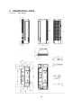
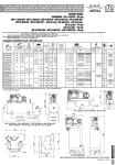
',0(16,21$/ '$7$
Indoor Unit
6$3n.67
79.0
284.0
60.0
46.5
50
7.0
67.0
( 80.0)
196
235
45.0
49.0
27.4
60.0
115.9
202.3
305.9
115.9
475.0
298
76.0
52
133.8
1061.9
23.0
95.0
305.9
115.9
( 80.0)
13
32
70
Wide tube Narrow tube
95.0
417.9
26.7
49.0
1055.0
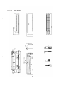
SAP–K256ST
Indoor Unit
14
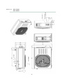
Wide tube service valve
¶12.70㧔1/2”㧕R22 (SAP-C186M)
¶15.88㧔5/8”) R22 (SAP-C256M)
ޓ
Narrow tube service valve
¶6.35㧔1/4”㧕R22
Outdoor Unit
6$3n&67
6$3n&67
5()5,*(5$17)/2:',$*5$0
Indoor Unit
6$3 n .67
6$3 n &67
Outdoor Unit
,QGRRU8QLW
2XWGRRU8QLW
Wide tube
Wide tube
service
valve
Accumulator
Compressor
Condenser
Evaporator
O.D.
ø12.7 mm
(1/2 ")
Narrow tube
Narrow
tube
service
valve
O.D.
ø6.35 mm
(1/4")
Indoor Unit
Capillary tube
6$3 n .67
Outdoor Unit
,QGRRU8QLW
2XWGRRU8QLW
Wide tube
Wide tube
service
valve
6$3 n &67
Accumulator
Compressor
Condenser
Evaporator
O.D.
ø15.88 mm
(5/8 ")
Narrow tube
O.D.
ø6.35 mm
(1/4")
Narrow
tube
service
valve
Capillary tube
,QVXODWLRQRI5HIULJHUDQW7XELQJ
,03257$17
Because capillary tubing is used in the outdoor unit, both the
wide and narrow tubes of this air conditioner become cold. To
prevent heat loss and wet floors due to dripping of
condensation, ERWKWXEHVPXVWEHZHOOLQVXODWHG with a
proper insulation material. The thickness of the insulation
should be a min. 8mm.
&$87,21
Insulation
Thickness:
Min. 8 mm
Thickness:
Min. 8 mm
Narrow tube
Wide tub
e
$IWHU D WXEHKDVEHHQ LQVXODWHG
QHYHUWU\WREHQGLWLQWR DQDUURZ
FXUYHEHFDXVH LWFDQFDXVHWKH WXEH
WR EUHDNRUFUDFN
15
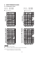
3(5)250$1&( '$7$
3HUIRUPDQFH FKDUWV
Indoor Unit
Outdoor Unit
6$3 n .67
6$3 n &67
Indoor Unit
Outdoor Unit
Cooling Characteristics
Cooling Characteristics
22
20
18
16
14
12
10
8
6
4
2
11
10
9
8
7
6
5
4
3
2
1
127(
......
6$3 n .67
6$3 n &67
Points of Rating condition
Black dots in above charts indicate the following rating conditions.
.
Cooling: Indoor air temperature 27°C D.B./ 19°C W.B.
Outdoor air temperature 35°C D.B./24°C W.B.
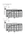
$LU7KURZ'LVWDQFH&KDUW
6$3 n .67
Indoor Unit
5RRPDLUWHPS
)DQVSHHG
+LJK
+RUL]RQWDOGLVWDQFHP
0
1
2
3
4
5
6
7
8
9
8
9
$[LVDLUYHURFLW\PV
9HUWLFDOGLVWDQFHP
0
1
2
3
4
: Flap angle 0 ,
: Flap angle 30 ,
: Axis air velocity 0
: Axis air velocity 30
6$3 n .67
Indoor Unit
5RRPDLUWHPS
)DQVSHHG
+LJK
+RUL]RQWDOGLVWDQFHP
0
1
2
3
4
5
6
7
$[LVDLUYHURFLW\PV
9HUWLFDOGLVWDQFHP
0
1
2
3
4
: Flap angle 0 ,
: Flap angle 30 ,
: Axis air velocity 0
: Axis air velocity 30
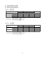
6. ELECTRICAL DATA
6-1. Electrical Characteristics
Indoor Unit
Outdoor Unit
SAP-K186ST
SAP-C186ST
Indoor Unit
Outdoor Unit
Fan Motor
Performance at
Rating Conditions
Running Amps.
A
0.17 / 0.17 / 0.17
Power Input
kW 0.035 / 0.035 / 0.035
Full Load Conditions Running Amps.
A 0.17 / 0.17 / 0.17
Power Input
kW 0.035 / 0.035 / 0.035
D.B. / 19
: Indoor Air Temperature 27
Outdoor Air Temperature 35 D.B.
Full Load Conditions : Indoor Air Temperature 32
D.B. / 23
Outdoor Air Temperature 48 D.B.
Rating Conditions
Indoor Unit
Outdoor Unit
Complete Unit
Fan Motor
Compressor
220-240V Single phase 50Hz
0.65 / 0.66 / 0.66
8.30 / 8.05 / 7.96
9.12 / 8.88 / 8.79
0.140 /0.149 / 0.156
1.814 / 1.832 / 1.877
1.989 / 2.016 / 2.068
0.65 / 0.66 / 0.66
12.60 / 10.29 / 9.93
13.42 / 11.12 / 10.76
0.140 /0.149 / 0.156
2.461 / 2.348 / 2.509
2.636 / 2.532 / 2.700
W.B.
W.B.
SAP-K256ST
SAP-C256ST
Indoor Unit
Outdoor Unit
Fan Motor
Fan Motor
Compressor
220-240V Single phase 50Hz
Performance at
Rating Conditions
Running Amps.
A 0.22 / 0.22 / 0.22
0.67 / 0.68 / 0.69
Complete Unit
11.66 / 11.78 / 12.40
12.55 / 12.68 / 13.31
kW 0.045 / 0.045 / 0.045 0.147 / 0.155 / 0.162 2.446 / 2.496 / 2.587
Full Load Conditions Running Amps.
A 0.22 / 0.22 / 0.22
0.67 / 0.68 / 0.69
17.31 / 14.80 / 17.42
Power Input
kW 0.045 / 0.045 / 0.045 0.147 / 0.155 / 0.162 3.356 / 3.247 / 3.711
2.638 / 2.696 / 2.794
Power Input
D.B. / 19
: Indoor Air Temperature 27
D.B.
Outdoor Air Temperature 35
Full Load Conditions : Indoor Air Temperature 32
D.B. / 23
Outdoor Air Temperature 48 D.B.
Rating Conditions
18
W.B.
W.B.
18.20 / 15.70 / 18.33
3.548 / 3.447 / 3.918
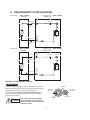
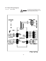
6-2. Electric Wiring Diagrams
Indoor Unit
SAP – K186ST
WARNING
19
To avoid electrical shock hazard, be sure to
disconnect power before checking, servicing
and/or cleaning any electrical parts.
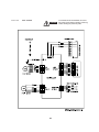
Indoor Unit
SAP – K256ST
WARNING
20
To avoid electrical shock hazard, be sure to
disconnect power before checking, servicing
and/or cleaning any electrical parts.
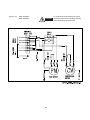
Outdoor Unit
SAP – C186ST
SAP – C256ST
WARNING
21
To avoid electrical shock hazard, be sure to
disconnect power before checking, servicing
and/or cleaning any electrical parts.
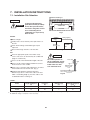
7. INSTALLATION INSTRUCTIONS
7-1. Installation Site Selection
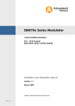
Wall-mounted Type
Indoor Unit
WARNING
To prevent abnormal heat
generation and the possibility
of fire, don’t place obstacles,
enclosures and grilles in front
of or surrounding the air
conditioner in a way that may
block air flow.
15 cm min.
5 cm
min.
5 cm
min.
INDOOR UNIT
Front View
Fig.1
AVOID:
Tubing length (L)
INDOOR
UNIT
direct sunlight.
nearby heat sources that may affect performance of
the unit.
Elevation
difference (H)
areas where leakage of flammable gas may be
expected.
places where large amounts of oil mist exist.
OUTDOOR
UNIT
Fig. 2a
Fig. 2
DO:
select an appropriate position from which every
corner of the room can be uniformly air-conditioned.
(High on a wall is best)
CAUTION
For stable operation of
the air conditioner, do not
install wall-mounted type
indoor units less than
1.5m from floor level.
select a location that will hold the weight of the unit.
select a location where tubing and drain hose have
the shortest run to the outside.
allow room for operation and maintenance as well as
unrestricted air flow around the unit. (Fig. 1)
install the unit within the maximum elevation
difference (H) above or below the outdoor unit and
within a total tubing length (L) from the outdoor unit
as detailed in Table 1 and Fig. 2a.
Indoor Unit
Wall
Minimum height
from floor level
1.5m
Floor level
Fig. 2b
Table 1
Max. Allowable Tubing
Length at Shipment
(m)
Limit of Tubing
Length (L)
(m)
Limit of Elevation
Difference (H)
(m)
Required Amount of
Additional Refrigerant
(g / m)
K186ST
5
30
7
20
K256ST
7.5
30
7
25
Model
If total tubing length becomes 5 or 7.5 to 30m (max.), charge additional refrigerant (R22) by 20 g / m or 25 g/m.
No additional charge of compressor oil is necessary.
22
Outdoor Unit
AVOID:
heat sources, exhaust fans, etc. (Fig. 3)
NO
damp, humid or uneven locations.
Exhaust fan
Hot air
Heat source
DO:
choose a place as cool as possible.
Outdoor unit
choose a place that is well ventilated.
allow enough room around the unit for air
intake/exhaust and possible maintenance.
(Figs. 4a and 4b)
Fig. 3
Fig 3
provide a solid base (concrete block, 10 40 cm
beams or equal), a minimum of 10 cm above ground
level to reduce humidity and protect the unit against
possible water damage and decreased service life.
(Fig.4c)
use lug bolts or equal to bolt down unit, reducing
vibration and noise.
Required space around the unit.
Obstacle above
Valve
side
Min. 25 cm
Min.
40 cm
Air discharge
Min
2m
Min
2m
Obstacle
Min.
5 cm
Min. 10 cm
Air discharge
Air intake
Top
TopView
View
Fig. 4a
Ground
Side View
Fig. 4b
Fig 4 C
Anchor bolts
(4 pcs.)
Rear air intake
Min. 10 cm
Side air intake
Concrete
or equal
Ab
t 10
ou
t4
Abou
0c
m
Fig. 4c
23
cm
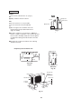
7-2. Remote Control Unit Installation Position
The remote control unit can be operated from either a non-fixed position or a wall-mounted position.
To ensure that the air conditioner operates correctly, do not install the remote control unit in the following places:
In direct sunlight
Behind a curtain or other place where it is covered
More than 8 m away from the air conditioner
In the path of the air conditioner's airstream
Where it may become extremely hot or cold
Where it may be subject to electrical or magnetic interference
Where there is an obstacle between the remote control unit and air conditioner (since a check signal is sent
from the remote control unit every 5 minutes)
Attaching the remote control unit to wall
Before mounting the remote control unit, press the ON/OFF operation button at the mounting location to make
sure that the air conditioner operates from that location (Fig.5). The indoor unit should make a beeping sound
to indicate that it has received the signal.
Rear side
Remote control
unit mount
Press
Mounting screws
4 x 16 (included)
Set in
place
Mounting screws
4 x 16 (included)
(For 256 model)
(For 186 model)
Hole
• To prevent loss of the remote control unit,
you can connect the remote control unit
to the mount by passing a string through
the remote control unit and attachment hole.
Fig.5
24
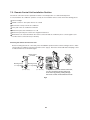
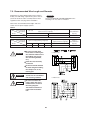
7-3. Recommended Wire Length and Diameter
Regulations on wiring diameter differ from locality to
locality. For field wiring requirements, please refer to
your local electrical codes. Carefully observe these
regulations when carrying out the installation.
NOTE
Refer to the WIRING SYSTEM DIAGRAM for the
meaning of "A" "B", and "C" in Table 2.
Table 2 lists recommended wire lengths and cross
section area for power supply systems.
Table 2
Cross Sectional
Area (mm2)
(A) Power Supply Wiring Length (m)
(B) Power Line Length (m)
(A) + (B)
Model
2 mm2
27
C186
Cross Sectional
Area (mm2)
Model
C256
WARNING
3.5 mm2
41
(C) Control Line Length (m)
(B) Power Line Length (m)
3.5 mm2
5.5 mm2
8 mm2
14 mm2
2 mm2
18
32
48
77
30
30A
Be sure to comply with
local codes on running the
wire from the indoor unit to
the outdoor unit (size of
wire and wiring method,
etc.).
For 186ST model:
No wire should be allowed
to touch refrigerant tubing,
the compressor, or any
moving part.
CAUTION
15A
Fuse or
Circuit Breaker
Capacity
(A) Power Supply Wiring Length (m)
Each wire must be firmly
connected.
WARNING
Fuse or
Circuit Breaker
Capacity
To avoid the risk of electric
shock, each air conditioner
unit must be grounded.
For 256ST model:
Be sure to connect the
power supply line to the
outdoor unit as shown in
the wiring diagram.
The indoor unit draws its
power from the outdoor
unit.
25
8. FUNCTION
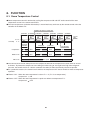
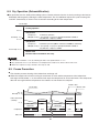
8-1. Room Temperature Control
䃂 Room temperature control is obtained by cycling the compressor ON and OFF under control of the room
temperature sensor in the remote control unit.
䃂 The room temperature (and other information) is transmitted every 3 minutes by the remote control unit to the
controller in the indoor unit.
Signal from remote control unit
3 minutes 3 minutes 3 minutes
Thermo.
OFF
set temp.
3 minutes
Thermo.
ON
Thermo.
OFF
3 minutes 3 minutes 3 minutes
Thermo.
ON
Thermo.
ON
Thermo.
ON
Thermo.
OFF
T+1 oC
T oC
More than
5 minutes
5 minutes
3 minutes
Room temp.
Compressor
ON
OFF
ON
OFF
ON
OFF
Outdoor fan
ON
OFF
ON
OFF
ON
OFF
Indoor fan
Set speed
䃂 The control circuit will not attempt to turn the compressor ON until the compressor has been OFF for at least
3 minutes. To protect the compressor from stalling out when trying to start against the high side refrigerant
pressure, the control circuit has a built-in automatic time delay to allow the internal pressure to equalize.
䃂 As a protective measure, the control circuit switches the compressor OFF after 5 minutes or more of compressor
operation.
䃂 Thermo. ON : When the room temperature is above T + 1°C (T°C is set temperature).
Compressor
ON
䃂 Thermo. OFF : When the room temperature is equal to or below set temperature T°C.
Compressor
OFF
26
8-2. Dry Operation (Dehumidification)
䃂 Dry operation uses the ability of the cooling cycle to remove moisture from the air, but by running at low level to
dehumidify without greatly reducing the room temperature. The air conditioner repeats the cycle of turning ON
and OFF automatically as shown in the chart below according to the room temperature.
Room temp.
Cooling operation
T+2 oC
䆃Dry A zone
Compressor :
Set temp. T oC
Continuous operation
FMI (indoor fan) : L (low speed) / LL (very low speed) intermittent ventilation
only while the compressor is ON.
T–1 oC
䆃Dry B zone
Compressor :
Intermittent operation (ON for 3 minutes and OFF for 9 minutes)
FMI (indoor fan) : L (low speed) / LL (very low speed) intermittent ventilation
only while the compressor is ON.
Room temp. 15 oC
Monitor zone
Both the indoor and outdoor units stop.
NOTE
䃂 Intermittent ventilation occurs by switching the indoor fan speed between L ¢ LL.
䃂 Dry operation does not occur when the room temperature is under 15°C, which is the monitor zone.
䃂 When the compressor stops, the indoor fan stops as well.
8-3. Freeze Prevention
L This function prevents freezing of the indoor heat exchange coil.
L When the compressor has been running for 10 minutes or more and the temperature of the indoor heat
exchange coil falls below –1°C, the control circuit stops the compressor for at least 6 minutes. The compressor
does not start again until the temperature rises above 8°C or 6 minutes has elapsed.
Thermo. OFF
Thermo. ON
Room temp.
T+1 oC
Set temp. T oC
Indoor heat exch.
coil temp.
More than
6 minutes
6 minutes
–1 oC
More than
10 minutes
Compressor
Indoor fan
ON
More than
10 minutes
OFF
ON
Set speed
ON
OFF
Set speed
27
ON
9. TROUBLESHOOTING
9-1. Check before and after troubleshooting
WARNING
Hazardous voltage can cause ELECTRIC SHOCK or
DEATH. Disconnect power or turn off circuit breaker
before you start checking or servicing.
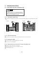
9-1-1. Check power supply wiring.
Check that power supply wires are correctly connected to terminals L and N on the terminal plate in the outdoor
unit.
For 186ST
For 256ST
9-1-2. Check inter-unit wiring.
Check that inter-unit wiring is correctly connected between indoor unit and outdoor unit.
9-1-3. Check power supply.
Check that voltage is in specified range (±10% of the rating).
Check that power is being supplied.
9-1-4. Check lead wires and connectors in indoor and outdoor units.
Check that coating of lead wires is not damaged.
Check that lead wires and connectors are firmly connected.
Check that wiring is correct.
28
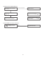
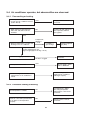
9-2. Air conditioner does not operate.
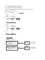
9-2-1. Circuit breaker trips (or fuse blows).
A. When the circuit breaker is set to ON, it is tripped soon. (Resetting is not possible.)
There is a possibility of ground fault.
Check insulation resistance.
If resistance value is 2M
or less, insulation is
”).
For 186ST
2
Indoor
unit
1
1
Power
supply
wiring
Outdoor
unit
Inter–unit
wiring
1
2
3
1
2
3
L
N
Circuit
breaker
Power
supply
Circuit
breaker
Power
supply
Ground
For 256ST
2
Indoor
unit
1
2
3
4
5
6
7
1
Inter–unit
wiring
1
Outdoor
unit
1
2
3
Power
supply
wiring
L
N
Ground
WARNING
* Set circuit breaker to OFF.
1
2
Remove both power supply wires
and inter-unit wires from terminal
plate in outdoor unit.
• Measure insulation resistance
of outdoor unit.
Remove inter-unit wires from
terminal plate in indoor unit.
• Measure insulation resistance
of indoor unit.
NO
Insulation of
outdoor unit
is defective.
• Measure insulation
resistance of electrical
parts in outdoor unit.
NO
Insulation of
indoor unit
is defective.
• Measure insulation
resistance of electrical
parts in indoor unit.
29
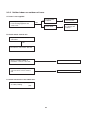
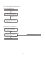
9-2-2. Neither indoor nor outdoor unit runs.
A. Power is not supplied.
• Check power supply.
Circuit breaker
is tripped.
Reset breaker.
Power failure
Wait for recovery
or contact power
company.
NO
Power is being supplied to the
outdoor unit.
B. Check remote control unit.
• Try to run with another remote
control unit.
OK
First remote control unit is defective.
• Check for residue buildup on
transmitter of remote control unit.
Clean transmitter.
• Check for residue buildup on remote
control receiver on front of indoor
unit.
Clean receiver.
C. Check transformer in the indoor unit.
• Measure resistance of primary and
secondary winding.
(TR)
30
D. Check fuse on the indoor PCB Ass'y.
• Check fuse on indoor PCB Ass'y
for continuity.
If fuse has been blown,
• Replace the fuse.
OK
• Check operation lamp to see
if light is ON.
• Measure resistance of indoor and
outdoor fan motor winding.
(FM)
Light is OFF
• Measure resistance of compressor
motor winding.
(CM)
• Indoor PCB Ass'y is defective.
E. Check TIMER on the remote control unit.
• Timer is turned ON. Check to see
if ON
is displayed on remote
control.
YES
Cancel the timer mode.
31
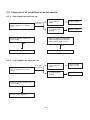
9-2-3. Only outdoor unit does not run.
A. Check setting temperature.
Is room temperature too low ?
NO
Try to lower setting temperature by
temperature setting button ( button).
Outdoor unit still does
not run.
• Check to see if inter-unit wiring is
correctly connected between indoor
and outdoor unit.
B. Check power relay in outdoor unit.
• Check voltage between terminals
No. 2 and No. 3 at terminal plate.
(AC 220 - 240 V)
OK
• Check coil terminal voltage between
terminals No. 5 and No. 6 at power
relay. (AC 220 - 240 V)
OK
Replace the power relay.
No voltage appears.
Check indoor PCB Ass'y.
32
9-3. Some part of air conditioner does not operate.
9-3-1. Only indoor fan does not run.
• Check fan rotation.
Turn fan gently once or twice by
hand.
• Check fan casing
foreign matter on
inside.
Fan cannot
be turned.
Remove foreign
matter or repair.
Fan motor burnout
or foreign matter in
bearings.
• Measure resistance of indoor fan
motor winding.
Repair or replace.
• When fan speed is changed, does
applied voltage between lead wires
BRN and WHT change as well ?
OK
NO
• Check fan motor capacitor.
• PCB Ass'y is defective.
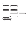
9-3-2. Only outdoor fan does not run.
• Check fan rotation.
Turn fan gently once or twice by
hand.
• Check fan casing
foreign matter on
inside.
Fan cannot
be turned.
Fan motor burnout
or foreign matter in
bearings.
• Measure resistance of outdoor fan
motor winding.
OK
• Check fan motor capacitor.
33
Remove foreign
matter or repair.
Repair or replace.
9-3-3. Only compressor does not run.
• Check compressor moter
capacitor.
• Overload relay is working.
YES
• Measure resistance of
compressor motor winding.
• Temperature of compressor
is abnormally high.
YES
YES
Refrigerant gas shortage.
NO
• Measure Power supply
voltage.
The voltage is too low.
No
Rotor may be locked up.
9-3-4. Only flap motor does not run.
• Measure resistance of flap motor
winding and connector.
34
Charge refrigerant gas (R22).
9-4. Air conditioner operates, but abnormalities are observed.
9-4-1. Poor cooling or heating.
• Check position of remote control unit.
• Cool air from air conditioner reaches
position directly.
YES
Change position of remote
control unit.
• Wide and narrow tubes between
indoor unit and outdoor unit are
insulated.
NO
Insulate both wide and narrow
tubes separately and then
tape together.
YES
• Measure temperature of suction and
discharge air of air conditioner.
Temperature
difference
is small.
Possibility of
gas shortage.
Charge refrigerant
gas (R22).
Temperature difference between
suction and discharge air is
large enough (approx. 10 deg. or more).
Check for clogging of air filter.
Clean filter.
Air filter is clogged.
• Fan speed is set to LOW.
YES
Set fan speed to either
HIGH or MEDIUM.
Reduce cooling load or
replace the air conditioner
with larger capacity.
• Review cooling load estimate,
if performance of air conditioner is
normal.
9-4-2. Excessive cooling or heating.
• Set temperature is suitable.
• Remote control unit is placed where
it can detect room temperature
properly.
Set temperature to higher
value using temperature
setting buttons of the remote
control unit.
NO
NO
Change position of remote
control unit.
35
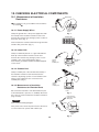
10. CHECKING ELECTRICAL COMPONENTS
Ground wire
10-1. Measurement of Insulation
Resistance
Clip
The insulation is in good condition if the resistance
exceeds 2M .
Probe
10-1-1. Power Supply Wires
Insulation
tester
Clamp the ground wire of the power supply wires with
the lead clip of the insulation resistance tester and
measure the resistance by placing a probe on either of
the power wires. (Fig. 1)
Fig. 1
Terminal plate
Then measure the resistance between the ground wire
and the other power wire. (Fig. 1)
Probe
10-1-2. Indoor Unit
Clamp an aluminum plate fin or copper tube with the
lead clip of the insulation resistance tester and
measure the resistance by placing a probe on each
terminal screw on the terminal plate. (Fig. 2)
Note that the ground line terminal should be skipped
for the check.
Clip
Copper
tube or
metallic part
Insulation
tester
Fig. 2
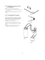
10-1-3. Outdoor Unit
Clamp a metallic part of the unit with the lead clip of
the insulation resistance tester and measure the
resistance by placing a probe on each terminal screw
where power supply lines are connected on the
terminal plate. (Fig. 2)
Probe
Clip
Copper
tube or
metallic part
10-1-4. Measurement of Insulation
Resistance for Electrical Parts
Insulation
tester
Disconnect the lead wires of the desired electric part
from terminal plate, capacitor, etc. Similarly disconnect
the connector. Then measure the insulation resistance.
(Figs. 3 and 4)
Fig. 3
From fan motor,
compressor and
other parts
NOTE
Refer to Electric Wiring Diagram.
Metallic
part
If the probe cannot enter the poles because the hole is
too narrow then use a probe with a thinner pin.
Probe
Clip
Insulation
tester
36
Fig. 4
10-2. Checking Continuity of Fuse
on PCB Ass'y
Fuse
Remove the PCB Ass’y from the electrical
component box. Then pull out the fuse from the PCB
Ass’y. (Fig. 5)
PCB Ass’y
Check for continuity using a multimeter as shown in
Fig. 6.
Fig. 5
10-3. Checking Motor Capacitor
Remove the lead wires from the capacitor terminals,
and then place a probe on the capacitor terminals as
shown in Fig. 7. Observe the deflection of the pointer,
setting the resistance measuring range of the
multimeter to the maximum value.
Fuse
The capacitor is “good” if the pointer bounces to a
great extent and then gradually returns to its original
position.
Fig. 6
The range of deflection and deflection time differ
according to the capacity of the capacitor.
Multimeter
Compressor motor
capacitor
Fan motor
capacitor
Fig. 7
37
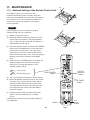
0$,17(1$1&(
Tab
$GGUHVV6HWWLQJRIWKH5HPRWH&RQWURO8QLW
The address can be set in order to prevent
interference between remote controllers when two
indoor units are installed near each other. The address
is normally set to “A.” To set a different address, it is
necessary to change the address on the second
remote controller.
)LJ
127(
Once changed, you cannot restore the original
address setting of the air conditioner.
(1) Switch on the power source.
(2) Break the address-setting tab marked “A” on the
second remote controller to change the address
(Fig. 1). When the tab is removed, the address is
automatically set to B (Fig. 2).
ACL button
(3) Press and hold the remote controller HIGH POWER
button and 1 HR TIMER button. At the same time,
press the ACL (reset) button. Use a thin object
such as the tip of a pen to press the ACL button.
When this has been done, “oP-1” (test run) appears,
blinking, in the remote controller clock display
area.
)LJ
(4) Each time the 1 HR TIMER button is pressed, the
display changes as shown below. Press this
button once to change the display to “oP-7”
(address setting). (Fig. 3)
Test run mode
Address setting mode
ON/OFF
operation
button
HIGH POWER
button
(5) “oP-7” has now been selected for address setting.
(6) Press the ON/OFF operation button on the remote
controller. (Fig. 3) Check that the “beep” signalreceived sound is heard from the second indoor
unit (approximately 5 times). The sound you hear
is the signal that the remote controller address
has been changed.
1 HR.TIMER
button
(7) Finally press the remote controller ACL (reset)
button to cancel the blinking “oP-7” display.
(Fig. 3)
Changing of the second remote controller address is
now completed.
ACL
(Reset)
Adress
button
)LJ
APPENDIX
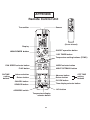
Remote Control Unit
HIGH
POWER
Sensor
Transmitter
(Cover closed)
Display
ON/OFF operation button
HIGH POWER button
1 HR. TIMER button
Temperature setting buttons (TEMP.)
FAN SPEED selector button
MODE selector button
FLAP button
ON TIME
setting
buttons
NIGHT SETBACK button
Advance button
Advance button
Return button
Return button
OFF TIME
setting
buttons
CANCEL button
CLOCK button
SENSOR button
Time display selector button
ACL button
ADDRESS switch
Temperature display
selector button
39
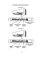
Unit Display and Operation Button
SAP-K186ST
TIMER
lamp
OPERATION
lamp
Remote control
receiver
ON/OFF
button
SAP-K256ST
TIMER
lamp
OPERATION
lamp
Remote control
receiver
ON/OFF
button
40
SANYO Electric Co.,Ltd.
Osaka, Japan