1
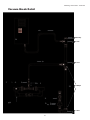
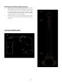
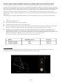
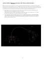
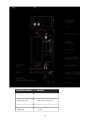
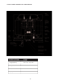
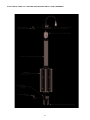
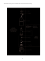
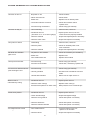
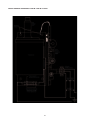
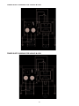
Plumbing Connections - continued
OPTIONAL CONTACT COLUMN INSTALLATION
Location
The contact column(s) should be installed after the injector manifold(s), within three (3) feet of a wall or solid mounting surface using
isolation valves to facilitate cleaning the diffuser, if needed. There should be as few elbows as possible between the injector(s) and the
contact column(s). Be sure to note the flow direction of the column(s).
Mounting To a Wall or Other Solid Mounting Surface Using the Hardware Kit
Refer to the diagrams on the next pages and follow these instructions:
1.
Locate the following items from the hardware kit:
• ‘L’ bracket
• two 1/2” concrete anchors with nuts and washers
• unistrut and protective end cap
• 6” clamp assembly with nut and bolt
2.
Mark the two holes for the ‘L’ bracket on the wall. The ‘L’ bracket should be in located above the center of the length of th
contact column. A foot or so from the top is ideal. Drill two 1/2” holes where you marked, about 31/2” to 4” deep. Insert one
concrete anchor into each hole with the threaded end sticking out. Slip the ‘L’ bracket over these threaded ends and tighten
down with the nuts and washers provided. This will cause the ends of the concrete anchors in the wall to expand and thus
secure the ‘L’ bracket to the wall.
3.
Bolt the unistrut to the ‘L’ bracket with two bolts, nuts and washers. NOTE: The unistrut may be cut to length if desired.
4.
Slip the two 6” clamp pieces into the unistrut around the contact column. Tighten bolt.
5.
Attach the protective end cap to the exposed end of the unistrut.
16