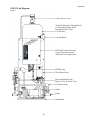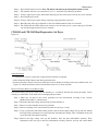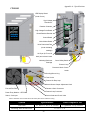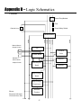
1
Ozone Systems
Installation & Operation Manual
POE10 ● POE12
Corona Discharge Ozone Generators
ClearWater Tech, LLC.
Integrated Ozone Systems
850-E Capitolio Way, San Luis Obispo, Ca 93401 • 805-549-9724 • Fax: 805-549-0306 • E-mail: [email protected] • www.cwtozone.com
Copyright © 2011 - ClearWater Tech, LLC • Reproduction of any kind is prohibited • LIT655 • Rev 081711
O3
INTRODUCTION
This Installation and Operation Manual is
written to assist in the installation, operation
and maintenance of ozone delivery systems
manufactured by ClearWater Tech, LLC.
This equipment has been designed using the
most modern materials and technology
available.
Please read this manual carefully and in its
entirety before proceeding with any
installation, operation or maintenance
procedure associated with this equipment.
Failure to follow these instructions could
result in personal injury, damage to the
equipment or reduced product performance.
-1-
In an ongoing effort to improve reliability and
operating efficiency, ClearWater Tech may find it
necessary to make changes to its products.
Therefore, the information contained in this
manual may not conform in every respect to
earlier versions of ClearWater Tech ozone system
found in the field. If you have any questions,
please contact your ClearWater Tech dealer or the
ClearWater Tech service department.
TABLE OF CONTENTS
Overview ............................................................................................................................. 3
Safety Information ............................................................................................................. 4
Theory of Operation/Product Description ...................................................................... 6
Installation – Getting Started ........................................................................................... 8
Installation – General ........................................................................................................ 9
Installation – Residential Well Side-Stream System .................................................... 10
Figure 1 – Residential Well Side-Stream System ......................................................... 10
Installation – Municipal or Community Residential Side-Stream System................. 13
Figure 2 – Municipal or Community Residential Side-Stream System ........................ 13
Installation – Residential Well Booster System ............................................................ 16
Figure 3 – Residential Well Booster System ................................................................ 16
Installation – Atmospheric Tank Recirculation System .............................................. 19
Figure 4 – Atmospheric Tank Recirculation System .................................................... 19
Installation – Single (Straight) Pass Filling System ...................................................... 22
Figure 5 – Single (Straight) Pass Filling System ......................................................... 22
Operation .......................................................................................................................... 25
Figure 6 – POE10 Unit Diagram ................................................................................. 25
Figure 7 – POE12 Unit Diagram ................................................................................. 26
Figure 8 – Vacuum Break Diagram ............................................................................. 28
Figure 9 – Time Delay Box – Inside View .................................................................... 29
Figure 10 – Time Delay Box – Front View .................................................................. 30
Figure 11 – Apex Interface Box – Front View.............................................................. 30
Figure 12 – POE10 Timing Table ................................................................................ 31
Maintenance ..................................................................................................................... 32
Figure 13 – Ozone Generator Cooling Fan Assembly ................................................. 33
Figure 14 – CD10/AD and CD12/AD Heat Regenerative Air Dryer ........................... 34
Figure 15 – CD10/AD and CD12/AD 1” Reaction Chamber – Exploded View .......... 36
Troubleshooting ............................................................................................................... 38
Appendix A – Specifications ........................................................................................... 41
Appendix B – Parts List .................................................................................................. 45
Appendix C – Maintenance Kit ...................................................................................... 46
Appendix D – Logic Schematics ..................................................................................... 47
Appendix E – Drive Module Input Voltages ................................................................. 59
-2-
OVERVIEW
How Ozone In Generated
Ozone is generated by exposing oxygen molecules (O2)
in an air stream to a controlled, high energy electrical
field. As the air stream passes through the electrical
field produced inside the ozone generator, some oxygen
molecules are split, forming single oxygen atoms (O1).
These oxygen atoms then recombine with other oxygen
molecules in the air stream, forming ozone (O3)
Oxygen (O2)
O2
Ozone (O2)
+
O1
=
O3
Electrical
Field
O2
+
O1
=
O3
Properties of Ozone
Ozone is the most powerful oxidizer available that can be safely used in water treatment1. It is used to treat
drinking water, bottled water, swimming pool water, waste water, food and beverage processing water, and in
many other applications. Ozone is effective in performing the following:
•
•
•
Molecular Weight
Disinfection – Bacterial disinfection,
inactivation of viruses and cysts.
Oxidation of Inorganics – Precipitates, iron,
manganese, sulfides nitrides and organicallybound heavy metals
Oxidation of Organics – Including organics
causing color, taste, and odor problems. Some
detergents and pesticides, phenols, VOCs,
turbidity control and micro-floccuity control and
micro-flocculation of soluble organics.
48
Odor
Readily detectable at concentrations
above 0.02 ppm in air
Color
Bluish in ozone generator cell, but
ozone/air mixture exiting generator is
invisible – even at high ozone
concentrations.
Gas Density:
2.144 grams/liter at 32°F
(Approximately 150% that of oxygen).
Solubility
Only partially soluble in water, but
about 10-20 times more soluble than
oxygen (at 68°F).
Benefits of Ozone Use
1
•
Ozone is generated on site – no transportation or storage is required
•
The most powerful oxidizer commercially available – very effective for
disinfection and oxidation without handling problems.
•
Ozone creates no potentially harmful by-products (such as THMs) – the only byproduct is oxygen.
•
Ozone leaves no telltale taste or odor.
Water Quality Association, “Ozone for POU, POE and Small Water System Water Treatment Applications,” Lisle, IL, 1999
-3-
Safety Information
Safety Warnings
Two aspects of ClearWater Tech ozone generators represent potential dangers – ozone gas and high voltage
electricity.
OZONE GAS
–
WARNING: HIGH CONCENTRATIONS OF OZONE GAS ARE
DANGEROUS TO HUMANS. LOW CONCENTRATIONS CAN
CAUSE IRRITATION TO THE EYES, THROAT AND
RESPIRATORY SYSTEM.
This ClearWater Tech corona discharge ozone generator
is creates ozone in high concentrations. While safety
precautions have been taken, entering the equipment
area should be avoided if ozone gas is detected. Ozone
has a very distinctive odor and is detectable at very low
concentrations (0.02 ppm), which is far below OSHA’s
maximum permissible exposure level of 0.1 ppm.
HIGH VOLTAGE – WARNING: CLEARWATER TECH OZONE GENERATORS
OPERATE AT HIGH VOLTAGE. DO NOT TAMPER WITH
OR DELIBERATELY BYPASS THE COVER OR SAFETY
SWITCHES BUILT INTO THE OZONE GENERATOR
UNLESS INSTRUCTED TO DO SO BY THIS MANUAL. IF
CONTACT IS MADE WITH OPERATING HIGH VOLTAGE
COMPONENTS, ELECTRIC SHOCK WILL OCCUR.
ClearWater Tech corona discharge ozone generators take line voltage and convert it to 48 VDC. A high voltage
transformer then boosts the voltage. Proper care must be used by a qualified electrician when making any internal
adjustments or performing any maintenance procedures.
-4-
IMPORTANT SAFETY INSTRUCTIONS
Safety Information
When installing and using this electrical equipment, basic safety precautions should always be followed,
including the following:
1.
READ AND FOLLOW ALL INSTRUCTIONS.
2.
SAVE THESE INSTRUCTIONS.
3.
All electrical connections should be made by a licensed, qualified electrician.
4.
Before attempting any electrical connections, be sure all power is off at the main circuit breaker.
5.
Install all electrical equipment at least five feet from any open body of water using non-metallic plumbing.
6.
Install check valves and a vacuum break to prevent water from contacting the electrical equipment.
7.
The electrical supply for this product must include a suitably rated switch or circuit breaker to open all
ungrounded supply conductors to comply with Section 422-20 of the National Electrical Code, ANSI/NFPA
70-1987. The disconnecting means must be readily accessible to the operator(s) but installed at least five
feet from any open body of water.
8.
Be sure to bond (ground) the system using the copper-bonding lug on the bottom of the ozone generator.
The system should be bonded with solid copper wire conforming to all local, state and national electrical
codes.
9.
The system should be sized appropriately for its intended use by a qualified professional familiar with the
application. This equipment must be validated by the manufacturer for its intended use; failure to do so
may void the warranty.
-5-
Theory of Operation/Product Description
Ozone is manufactured in the CD ozone generator by drawing in air, which is composed of 20% oxygen (O2), and
exposing it to multiple high voltage electrical discharges. This causes a percentage of the oxygen molecules to
dissociate and reassemble as ozone (O3). The ozone is drawn into the water by an injector/mixer, killing any
bacteria, viruses or mold spores it contacts. Ozone is generated on-site, eliminating the need to store toxic and
corrosive chemicals. The corona discharge method is the most efficient way to produce large amounts of ozone.
3 - O2
2 - O3
Chemical Formula (simplified) for Corona Discharge Ozone
In contrast to ultraviolet ozone generators, corona discharge systems produce a much higher concentration of
ozone and in much larger quantities. In addition, the annual expense of replacing lamps and checking ballasts is
unnecessary with corona discharge systems. Corona discharge ozone generation is the most economical and
effective method to use on most water treatment applications.
ClearWater Tech manufactures high output corona discharge systems capable of producing enough ozone to
oxidize iron, sulfide, manganese and act as an efficient sanitizer in a variety of applications. Ozone reacts to
waterborne contaminants significantly faster than other disinfectants and the primary by-product is pure oxygen.
ClearWater Tech ozone systems are built with the finest components available. All are air cooled and are most
efficient when used with a venturi injection system to create the best possible contact and mixing of ozone while
maintaining a high level of safety.
Product Description
The POE10/12 skid mounted systems from ClearWater Tech are the first small systems to offer high quality
components, a built-in time delay system and innovative solutions to the problems usually associated with “one
size fits all” ozonation systems. The POE10 and POE12 systems are self-contained, pre-plumbed and pre-wired,
offering simple installation and “works the first time” confidence.
The systems come completely assembled and water tested from ClearWater Tech. Its design allows the installer
to place the system in up to five different configurations by simply changing the inlet and outlet connections.
Air Preparation
ClearWater Tech corona discharge ozone generators require a source of clean, dry, oil-free, oxygen-enriched or
dry air for effective ozone production. To meet that need, the POE10 and POE12 use an internal heat regenerative
dry air system. The heat regenerative system operates via a vacuum which draws in ambient air and dries it to a 10 to -20˚F dew point at 20% oxygen purity. The CD10/AD and CD12/AD (“AD” represents Air Dryer)
incorporate a heat regenerative air dryer system, rated with a duty cycle of no more than 10 hours of operation in a
24 hour period in conditions up to 75% relative humidity non-condensing. Due to the operation of the internal air
dryer, continuous power must be applied to the CD10/AD and CD12/AD for proper operation. As the ambient air
travels through the dryer chambers the sieve material inside traps the moisture from the air and allows the oxygen
to pass to the ozone reaction chamber. The heat, generated by the heating rods inside the dryer chamber, then
evaporates the moisture that has been trapped in the sieve and expels off the top of the sieve bed. The two dryer
chambers and attached 3-way solenoid valve operate on a timed cycle. Dryer chamber 1 heats first evaporating
moisture for 1-1/2 hours, while the solenoid is energized allowing the vacuum from the venturi to draw air flow
through dryer chamber 2. During this time the “AIR PREP” LED will flash and “DRYER 1” LED will be
-6-
Theory of Operation/Product Description
illuminated continuously. After the 1-1/2 hours there is a 1/2 hour cool down period, power to dryer chamber 1
will be discontinued, correspondingly “DRYER 1” LED will not be illuminated. Note: The “AIR PREP” LED
will remain flashing throughout the cycle. After the cool down period dryer chamber 2 will heat and the solenoid
valve will de-energize, allowing vacuum from the venturi to draw air flow through dryer chamber 1. During this
time the “AIR PREP” LED will flash and “DRYER 2” LED will be illuminated continuously. After 1-1/2 hours
there is a 1/2 hour cool down period when power to dryer chamber 2 will be discontinued; correspondingly,
“DRYER 2” LED will not be illuminated. After this 1/2 hour cool down, the air dryer cycle will repeat.
Ozone Generator
The feed gas is drawn out of the air dryers and through the ozone generator by the vacuum created at the ozone
injector. An external air flow meter and vacuum gauge is provided to control and monitor the air flow and
vacuum through the ozone generator.
As the feed gas enters the thermally-protected reaction chambers inside the ozone generator, some of the oxygen
molecules are split while passing through the high voltage electrical field (the “corona”), forming single oxygen
atoms (O1). These oxygen atoms then recombine with other oxygen molecules in the air stream, forming ozone.
Ozone Injection/Contacting
The ozone injector serves two purposes: One, it creates
the vacuum required to safely draw the ozone gas from
the ozone generator and two, it provides a means by
which the ozone gas can become dissolved in water. A
very dynamic injection process is required to
effectively dissolve ozone in water.
ClearWater Tech injection systems use only Mazzei®
injectors for maximum mass transfer efficiency. The
injector produces a cavitation effect, enabling the ozone
gas to join the water stream in the form of extremely
tiny bubbles. These bubbles must be as small as
possible in order to increase the ratio of bubble surface
area to the amount of ozone entering the water.
A Short Course in Fine Bubbles
Lesson 1 – The large bubble (20mm) has a
volume of 4.19 cm3 and a surface area of
12.6 cm2.
Lesson 2 – 296small bubbles (3mm) could be
made from the large bubble in lesson 1. They
would have a total surface area of 83.6cm2. This
is 6.6 times the surface area of the large bubble.
Lesson 3 – Theoretically, 6.6 times as much
water could be ozonated with the same
amount of ozone!
Ozone Destruct
Depending on where the POE10 or POE12 is installed, an ozone destruct system may be needed to ensure safe
operation. The ClearWater Tech off-gas destruct systems consists of two components: the ozone destruct unit (a
heated chamber filled with manganese dioxide and copper oxide) and a water trap. Used in conjunction with the
off-gas vent provided at the top of the contact tank, the ozone destruct system is an effective way to vent the
contact vessel(s) when it is impractical to send the off-gas to atmosphere or reintroduce it to the water.
-7-
Installation – Getting Started
Shipping Terms
Unless special arrangements have been made, the ozone equipment will be
shipped FOB ClearWater Tech’s factory in San Luis Obispo, CA. The freight
charges will be prepaid and billed or shipped freight collect. Transfer of liability
to the freight company and the customer occurs as the equipment leaves the
factory loading dock and is accepted by the freight line.
Freight Inspection
All equipment should be thoroughly inspected immediately upon delivery. If any
damage is noticed, promptly notify the freight line and request an on-site
inspection.
Unpacking
Compare the ozone system equipment received to the packing list provided. Before beginning any installation
procedures, thoroughly inspect all components for damage. If damage is noticed, promptly notify the freight
carrier and request an on-site inspection. Inspect all packing materials for small parts before discarding. Inspect all
plumbing, fittings and tubing for packing material that may have become lodged in openings.
Equipment Placement
When placing the ozone system components in the equipment room, make sure to consider safety, maintenance
requirements, local building and fire codes, etc. The components should be easily accessible by the operators,
including equipment access doors and electrical hook-up boxes. All meters, gauges, indicator lights, and switches
should be visible and accessible. Dimensional drawings of the PEO10 and PEO12 are included in Section A of the
Appendix.
A total of 10’ of ozone vent tubing is supplied to allow the contact vessel auto vent to be vented out of the
building if an ozone destruct unit is not ordered.
Mounting holes are located on the bottom skid rails, allowing the unit to be secured to the floor. Mounting
hardware is not provided.
Like any electronic component, performance and longevity is enhanced by favorable operating conditions. Also,
since the ozone generator is air-cooled, a relatively dust-free, well-ventilated area is required. No caustic
chemicals should be stored in the area surrounding the equipment. A minimum clearance of six inches from the
vents on the cover of the ozone generator is required.
The POE10/12 enclosures are not designed to withstand outdoor elements, including direct contact with water
and/or temperature extremes. Therefore, the equipment must be installed in an environment consistent with the
following operating parameters:
•
•
•
Ambient temperature range: 20°F (-6.5°C) to 95°F (35°C) continuous. If the temperature around the
equipment consistently exceeds 95°F (35°C), additional air-cooling must be provided.
Humidity: 0 – 90% relative humidity, non-condensing environment
Line voltage: +/-10% of rated input
Note: Equipment installed in extreme environmental conditions will void manufacturer's warranty.
Allow room for the peripheral equipment (if any)
-8-
Installation – General
The POE10/12 is factory plumbed with 1” schedule 80 PVC pipe for flow rates from 5 to 18 gpm. This pipe size
should be maintained in the plumbing connections.
NOTES:
• Adequate use of unions and isolation valves is
strongly
recommended
to
facilitate
maintenance and repairs.
• Use Schedule 80 PVC for all plumbing
connections wherever possible. Plumbing size
requirements are dictated by the water flow
characteristics of the system.
• Make sure to use proper plumbing practices
and secure all plumbing and system equipment
according to local codes.
• Secure all plumbing with unistrut or similar
hardware.
• Ozone is a powerful oxidizer and will degrade
certain materials. Use ozone-compatible
plumbing materials for section(s) of the system
that will come in contact with ozone dissolved
in water. The following is a list of materials that
are compatible with ozone:
• Viton
• Stainless Steel (300 series)
• Kynar
• EPDM
• Teflon
• Concrete
• Silicon
• Schedule 80 PVC
• Hepalon
• Schedule 40 PVC
• Depending
on
the
application,
other
components (psi gauge, flow meter, etc.) may be
installed to assist in monitoring system
parameters.
Tubing Connections
All tubing connections between the ozone generator, vacuum break and injector manifold have been completed at
the factory. 1/4” Teflon® tubing is used for all ozone connections. Important: Do not replace this tubing with
any other kind.
Off-Gas Vent Installation
A stainless steel off-gas vent is supplied with the POE units. This vent is installed on the 3/4” male pipe
connection located on the top of the contactor. Use Teflon® tape or an approved pipe sealant for this connection
if removal is needed.
Teflon® off-gas vent tubing is supplied with the POE system. If an ozone destruct unit is not purchased, this
tubing should be connected from the 1/4” Teflon® compression fitting supplied with the contact vessel automatic
air vent to a safe location outside the building.
On the following pages are the five most common installations:
•
•
•
•
•
Residential Well Side Stream System
Municipal or Community Residential Side Stream System
Residential Well Booster System
Atmospheric Tank Recirculation System
Single (Straight) Pass Filling System.
Choose the installation which matches yours and follow the installation and start-up instructions for that
installation and then proceed to the OPERATION section which follows the installation sections
-9-
Installation – Residential Well Side-Stream System
In this configuration the POE system is placed between the well head and the pressure tank with any applicable
filtration after the pressure tank. Piping from the well is connected to the POE system inlet tee under the injector
manifold. The side connection of the POE system outlet tee is piped to the system check valve and pressure
switch prior to the pressure tank inlet. The booster pump is piped to the top connection of the POE system outlet
tee completing the plumbing installation of the unit.
In a residential well configuration the time delay controller is wired to the pressure switch. This will allow the
time delay controller to receive a 120 Volt signal whenever the pressure switch is activated. Attach the indicated
wire from the three position AMP® pin connector on the time delay controller to one of the two 120 volt wires on
the pump side of the pressure switch. The POE system main power cord should be plugged into a dedicated 20
amp receptacle capable of handling the power requirement of the POE system.
The POE system comes from the factory with no time delay preset. It will operate the pump and ozone portion of
the unit with the operation of the pressure switch. To set the delay timer for your water conditions refer to the
time delay controller setting instructions.
Residential Well Side-Stream System
Figure 1
Installation on a Residential Well Side Stream System
1.
When installing the POE10/12 system be sure to place the equipment in a sheltered location protected
from direct rain and dusty conditions. Freezing temperatures and temperatures in excess of 100°F for
extended periods of time will damage the equipment and void the warranty.
2.
The POE10/12 system comes with 6’ of 12/3 NEMA 5-15 (standard residential) power cord and requires
a dedicated 20 amp receptacle. The unit should be placed within 4’ of the receptacle. Use of an extension
cord over 6’ in length or less than 12/3 gauge will result in damage to the equipment
3.
It is recommended that a three valve maintenance bypass be added when installing the POE system. This
is a standard practice that will allow the existing system to operate while maintenance is being performed
on the POE system.
-10-
Installation – Residential Well Side-Stream System
4.
When connecting to the 1” threaded Schedule 80 PVC inlet and outlet tees on the POE unit. It is
recommended that good plumbing practice be followed by installing unions at the inlet and outlet
connections. Care should be taken not to apply heat or pipe sealants that might deteriorate the PVC tees.
All connecting piping should be braced and plumbed so that no torsional loads or stress be exerted on the
inlet or outlet fittings. NOTE: If the well pump is not equipped with a check valve, an auxiliary check
valve must be installed between the well pimp and the
5.
After connecting the piping from the well to the inlet tee and piping the outlet tee side connection to the
system check valve before the pressure tank. Plumb the 1” threaded outlet tee top connection to the 11/4”
threaded connection on the recirculation pump inlet. A union at the pump connection will make any
future service easier. 1” schedule 80 PVC or 1” copper pipe should be used. Do not apply any heat to the
outlet tee connection.
6.
Fill the clear view vacuum break with water by turning the fill/overflow fitting by hand counter clockwise
to face upwards. Add water until it overflows. Return the fitting to the downwards facing position.
Connect the provided 3/4” braided tubing to this fitting and plumb to a floor drain or position so that any
water flow from this line will be easily noticed. Do not plumb this line to any drain above the elevation
of the overflow fitting. Follow all regulations concerning backflow and air gap connections. Periodic
water flows from this line can occur. Failure to connect this line to an appropriate drain may result in
water damage should a check valve fail. ClearWater Tech is not responsible for any damage resulting
from water overflow from the clear view vacuum break.
7.
Disconnect the 1/4” Teflon® air vent tubing from the automatic air release at the top of the contact tank.
Slowly open the maintenance bypass or activate the well pump. Allow the POE system contact tank to
fill until no air is released from the tank. Reconnect the tubing. Open all valves fully and check for leaks.
8.
After disconnecting power to the well pump and pressure switch. Connect the center wire (MCI) on the
time delay controllers 3 position AMP® pin connector to one of the two 120V power wires leading to the
well pump in the pressure switch. This connection must be made on the “pump” side of the switch.
Reconnect the power.
Startup Procedures on a Residential Well Side Stream System
1.
The POE10/12 systems are shipped from ClearWater Tech with the time delay controller in the no delay
position (no time indicated on the time delay relay). For initial adjustment of the venturi feed gas flow, it
is recommended that one minute be set to allow for venturi adjustment.
2.
After unplugging the POE unit, remove the cover from the time delay relay. Referring to the adjustments
outlined in the time delay relay section, set the relay for one minute. Depending on your installation
removal of the relay for this procedure maybe necessary. The relay maybe removed for adjustment only
if the POE unit is unplugged. Removal of this relay while the unit is plugged in may result in damage and
will void the warranty. After setting one minute on the relay, plug the POE system in again.
3.
Activate the CD10AD/12AD by depressing the ON/OFF rocker switch on the underside of the unit. After
several seconds the green main power light, High Voltage drive lights and the red External Loop indicator
will come on. The amber dryer indicator lamp will start blinking and one of the two amber dryer chamber
lights will be on. At this time none of the ten upper ozone output indicator lights should be on. They will
be activated with the ozone generator portion of the CD10AD/12AD by the time delay relay.
4.
The POE10/12 systems are shipped from ClearWater Tech with the venturi water bypass valve and the
feed gas control valve in the closed position. This is the correct position for initial startup.
-11-
Installation – Residential Well Side-Stream System
5.
Start the POE unit by lowering the system pressure to engage the well pump. This can be done by
opening any hose bib or faucet downstream of the pressure tank. When the pressure switch activates, the
POE system booster pump and ozone generator will now turn on.
6.
You will now have the normal pump cycle and one additional minute to adjust the venturi feed gas flow.
Slowly open the feed gas flow valve at the vacuum break. This will cause water to rise in the vacuum
break and dried air to flow in the SCFH gauge under the CD10AD/12AD ozone generator. Adjust the
feed gas control valve until the SCFH gauge reads between 3-5 SCFH for CD10/AD and 6-8 SCFH for
CD12/AD. If this takes more than one pump cycle or if water is drawn into the venturi, refill the vacuum
break and recycle the well pump as necessary.
-12-
Installation – Municipal or Community Residential Side-Stream System
In this configuration the POE system is placed between the water service and the first treated outlets. Where
possible, irrigation connections should be made before the POE system. As with the installation of any piece of
water treatment equipment, a three valve maintenance bypass should be installed. Piping from the water service
is connected to the POE system inlet tee under the injector manifold. The side connection of the POE system
outlet tee is then piped back to the distribution system or bypass. The booster pump inlet is piped to the top
connection of the POE system outlet tee completing the plumbing installation. Any filtration dictated by water
conditions should be installed with its own maintenance bypass downstream of the POE unit.
In a residential municipal configuration the time delay controller is wired to a flow switch on the house side or
downstream of the POE unit. This will allow the time delay controller to receive a dry contact signal whenever
there is a demand for water. This flow switch is connected to the indicated wires of the time delay controller’s
three position AMP® pin connector. The POE system main power cord should be plugged into a dedicated 20
amp receptacle capable of handling the power requirement of the POE system.
The POE system comes from the factory with no time delay preset. It will operate the pump and ozone portion of
the unit with the operation of the flow switch. To set the delay timer for your water conditions refer to the time
delay controller setting instructions.
Municipal or Community Residential Side-Stream System
Figure 2
Installation Guide on a Municipal/Community Residential Side Stream System
1.
When installing the POE10/12 system be sure to place the equipment in a sheltered location protected
from direct rain and dusty conditions. Freezing temperatures and temperatures in excess of 100°F for
extended periods of time will damage the equipment and void the warranty.
2.
The POE10/12 system comes with a 6’ 12/3 NEMA 5-15 (standard residential) power cord and requires a
dedicated 20 amp receptacle. The unit should be placed within 4’ of the receptacle. Use of an extension
cord over 6’ in length or less than 12/3 gauge will result in damage to the equipment.
-13-
Installation – Municipal or Community Residential Side-Stream System
3.
It is recommended that a three valve maintenance bypass be added when installing the POE system. This
is a standard practice that will allow the existing system to operate while maintenance is being performed
on the POE system.
4.
When connecting to the 1” threaded Schedule 80 PVC inlet and outlet tees on the POE unit. It is
recommended that good plumbing practice be followed by installing unions at the inlet and outlet
connections. Care should be taken not to apply heat or pipe sealants that might deteriorate the PVC tees.
All connecting piping should be braced and plumbed so that no torsional loads or stress be exerted on the
inlet or outlet fittings.
5.
After connecting the piping from the water service to the inlet tee and piping the outlet tee side
connection back to the system or bypass. Plumb the 1” threaded outlet tee top connection to the 1 1/4”
threaded connection on the recirculation pump inlet. A union at the pump connection will make any
future service easier. 1” schedule 80 PVC or 1” copper pipe should be used. Do not apply any heat to the
inlet or outlet tee connections.
6.
Fill the clear view vacuum break with water by turning the fill/overflow fitting by hand counter clockwise
to face upwards. Add water until it overflows. Return the fitting to the downwards facing position.
Connect the provided 3/4” braided tubing to this fitting and plumb to a floor drain or position so that any
water flow from this line will be easily noticed. Do not plumb this line to any drain above the elevation
of the overflow fitting. Follow all regulations concerning backflow and air gap connections. Periodic
water flows from this line can occur. Failure to connect this line to an appropriate drain may result in
water damage should a check valve fail. ClearWater Tech is not responsible for any damage resulting
from water overflow from the clear view vacuum break.
7.
Disconnect the 1/4” Teflon® air vent tubing from the automatic air release at the top of the contact tank.
Slowly open the water service or maintenance bypass. Allow the POE system contact tank to fill until no
air is released from the tank. Reconnect the tubing. Open all valves fully and check for leaks.
8.
Connect the two outer wires (dry contact) on the tine delay controllers 3 position AMP® pin connector to
a flow switch installed downstream of the POE unit.
Startup Procedures on a Municipal/Community System
1.
The POE10/12 systems are shipped from ClearWater Tech with the time delay controller in the no delay
position (no time indicated on the time delay relay). For initial adjustment of the venturi feed gas flow, it
is recommended that one minute be set to allow for venturi adjustment. This will not necessary on a
Municipal type of system if a hose bib or faucet can be left open maintaining the flow switch dry contact.
If a this is not possible refer to step 2.
2.
After unplugging the POE unit, remove the cover from the time delay relay. Referring to the adjustments
outlined in the time delay relay section, set the relay for one minute. Depending on your installation
removal of the relay for this procedure maybe necessary. The relay maybe removed for adjustment only
if the POE unit is unplugged. Removal of this relay while the unit is plugged in may result in damage and
will void the warranty. After setting one minute on the relay, plug the POE system in again.
3.
Activate the CD10AD/12AD by depressing the ON/OFF rocker switch on the underside of the unit. After
several seconds the green main power light, High Voltage drive lights and the red External Loop indicator
will come on. The amber dryer indicator lamp will start blinking and one of the two amber dryer chamber
lights will be on. At this time none of the ten upper ozone output indicator lights should be on. They will
be activated with the ozone generator portion of the CD10AD/12AD by the time delay relay.
4.
The POE10/12 systems are shipped from ClearWater Tech with the venturi water bypass valve and the
feed gas control valve in the closed position. This is the correct position for initial startup.
-14-
Installation – Municipal or Community Residential Side-Stream System
5.
Start the POE unit by opening any hose bib or faucet downstream of the POE system. When the flow
switch activates, the POE system booster pump and ozone generator will now turn on.
6.
You may now adjust the feed gas flow to the venturi. Slowly open the feed gas flow control valve at the
vacuum break. This will allow water to rise in the vacuum break riser column and dried air to flow in the
SCFH gauge under the CD10AD/12AD ozone generator. Adjust the feed gas control valve until the
SCFH gauge reads between 3-5 SCFH for CD10/AD and 6-8 SCFH for CD12/AD. Should water be
drawn into the venturi. Refill the vacuum break and recycle the system as necessary.
-15-
Installation – Residential Well Booster System
In this configuration the POE system is placed between the well head and the pressure tank with any applicable
filtration after the pressure tank. Piping from the well is connected to the POE system booster pump inlet. The
side connection of the POE system outlet tee is piped to the system check valve and pressure switch prior to the
pressure tank inlet. Threaded plugs (1” PVC) provided with the POE unit should be inserted into the side
connection of the POE inlet tee and the top connection of the POE outlet tee.
In a standard residential well configuration the time delay controller is wired to the pressure switch. This will
allow the time delay controller to receive a 120 Volt signal whenever the pressure switch is activated. Attach the
indicated wire from the time delay controller’s three position AMP® pin connector to one of the two 120 volt
wires on the pump side of the pressure switch. The POE system main power cord should be plugged into a
dedicated 20 amp receptacle capable of handling the power requirement of the POE system.
Residential Well Booster System
Figure 3
Installation on a Residential Well Booster System
1.
When installing the POE10/12 system be sure to place the equipment in a sheltered location protected
from direct rain and dusty conditions. Freezing temperatures and temperatures in excess of 100°F for
extended periods of time will damage the equipment and void the warranty.
2.
The POE10/12 system comes with a 6’ 12/3 NEMA 5-15 (standard residential) power cord and requires a
dedicated 20 amp receptacle. The unit should be placed within 4’ of the receptacle. Use of an extension
cord over 6’ in length or less than 12/3 gauge will result in damage to the equipment.
3.
It is recommended that a three valve maintenance bypass be added when installing the POE system. This
is a standard practice that will allow the existing system to operate while maintenance is being performed
on the POE system.
4.
When connecting to the 1” threaded Schedule 80 PVC inlet and outlet tees on the POE unit. It is
recommended that good plumbing practice be followed by installing unions at the inlet and outlet
-16-
Installation – Residential Well Booster System
connections. Care should be taken not to apply heat or pipe sealants that might deteriorate the PVC tees.
All connecting piping should be braced and plumbed so that no torsional loads or stress be exerted on the
inlet or outlet fittings. Do not apply any heat to the inlet or outlet tee connections.
5.
Connect the piping from the well to the 11/4” threaded connection on the recirculation pump inlet. A
union at the pump connection will make any future service easier. Connect the outlet tee side connection
to the system check valve before the pressure tank. Install the 1” threaded PVC plugs supplied with the
POE unit into the side connection of the inlet tee and the top connection of the outlet tee.
6.
Fill the clear view vacuum break with water by turning the fill/overflow fitting by hand counter clockwise
to face upwards. Add water until it overflows. Return the fitting to the downwards facing position.
Connect the provided 3/4” braided tubing to this fitting and plumb to a floor drain or position so that any
water flow from this line will be easily noticed. Do not plumb this line to any drain above the elevation
of the overflow fitting. Follow all regulations concerning backflow and air gap connections. Periodic
water flows from this line can occur. Failure to connect this line to an appropriate drain may result in
water damage should a check valve fail. ClearWater Tech is not responsible for any damage resulting
from water overflow from the Clear view Vacuum Break.
7.
Disconnect the 1/4” Teflon® air vent tubing from the automatic air release at the top of the contact tank.
Slowly open the maintenance bypass or activate the well pump. Allow the POE system contact tank to
fill until no air is released from the tank. Reconnect the tubing. Open all valves fully and check for leaks
8.
After disconnecting power to the well pump and pressure switch. Connect the center wire (MCI) on the
time delay controllers 3 position AMP® pin connector to one of the two 120V power wires leading to the
well pump in the pressure switch. This connection must be made on the “pump” side of the switch.
Reconnect the power.
9.
With the system up to pressure and the well pump off. Plug in the main power cord to the POE system.
Switch the CD10AD/12AD ozone generator ON. After a few seconds the main power light, HV drive
light and external loop indicator lights should come on. The dryer power indicator should start blinking
and one of the two dryer chamber lights will be on. At this time none of the ten upper ozone output
indicator lights should be on. They will be activated with the ozone generator and time delay relay by the
pressure switch.
Startup Procedures on a Residential Well Booster System
1.
The POE10/12 systems are shipped from ClearWater Tech with the time delay controller in the no delay
position (no time indicated on the time delay relay). For initial adjustment of the venturi feed gas flow, it
is recommended that one minute be set to allow for venturi adjustment.
2.
After unplugging the POE unit, remove the cover from the time delay relay. Referring to the adjustments
outlined in the time delay relay section, set the relay for one minute. Depending on your installation,
removal of the relay for this procedure maybe necessary. The relay maybe removed for adjustment only
if the POE unit is unplugged. Removal of this relay while the unit is plugged in may result in damage and
will void the warranty. After setting one minute on the relay, plug the POE system in again.
3.
The POE10/12 systems are shipped from ClearWater Tech with the venturi water bypass valve and the
feed gas control valve in the closed position. This is the correct position for initial startup.
4.
Start the POE unit by lowering the system pressure to engage the pressure switch/well pump. This can be
done by opening a hose bib or faucet downstream (house side) of the pressure tank. When the pressure
switch activates the well pump, the POE system booster pump and ozone generator will turn on.
-17-
Installation – Residential Well Booster System
5.
You may now adjust the feed gas flow to the venturi. Slowly open the feed gas flow control valve at the
vacuum break. This will allow water to rise in the vacuum break riser column and dried air to flow in the
SCFH gauge under the CD10AD/12AD ozone generator. Adjust the feed gas control valve until the
SCFH gauge reads between 3-5 SCFH for CD10/AD and 6-8 SCFH for CD12/AD. Should water be
drawn into the venturi., refill the vacuum break and recycle the system as necessary
-18-
Installation – Atmospheric Tank Recirculation System
In this configuration the POE system is placed adjacent to the tank to be treated. Piping from the tank bottom is
connected to the POE system booster pump inlet. The POE system outlet tee side connection should be piped
back to the bottom of the tank. Threaded plugs (1” PVC) provided with the POE unit should be inserted into the
side connection of the POE system inlet tee and the top connection of the POE system outlet tee.
In this configuration the time delay controller can be activated by:
1. A flow switch on the tank fill line
2. The tank fill float switch
3. A 24 hr timer
Follow the instructions in the time delay controller section for connecting these types of switches to the time
delay controller’s three position AMP® pin connector. The POE system main power cord should be plugged into
a dedicated 20 amp receptacle capable of handling the power requirement of the POE system.
Atmospheric Tank Recirculation System
Figure 4
Installation on an Atmospheric Tank Recirculation System
1.
When installing the POE10/12 system be sure to place the equipment in a sheltered location protected
from direct rain and dusty conditions. Freezing temperatures and temperatures in excess of 100°F for
extended periods of time will damage the equipment
2.
The POE10/12 system comes with a 6’ 12/3 NEMA 5-15 (standard residential) power cord and requires a
dedicated 20 amp receptacle. The unit should be placed within 4’ of the receptacle. Use of an extension
cord over 6’ in length or less than 12/3 gauge will result in damage to the equipment.
3.
When connecting to the 1” threaded Schedule 80 PVC inlet and outlet tees on the POE unit. It is
recommended that good plumbing practice be followed by installing unions at the inlet and outlet
-19-
Installation - Atmospheric Tank Recirculation System
connections. Care should be taken not to apply heat or pipe sealants that might deteriorate the PVC tees.
All connecting piping should be braced and plumbed so that no torsional loads or stress be exerted on the
inlet or outlet fittings. Do not apply any heat to the inlet or outlet tee connections.
4.
Plumb from the tank outlet or a dedicated bulkhead fitting in the bottom 25% of the tank to the 11/4”
threaded connection on the recirculation pump inlet. An isolation valve at the tank and a union at the
pump connection will make any future service easier. Then connect the side connection on POE unit
outlet tee back to the bottom 25% of the tank. If necessary return piping to the tank can be plumbed up
and over the side of the tank. It is still good practice to continue this piping to the lower 25% of the tank.
1” schedule 80 PVC or 1” copper pipe should be used. Install the 1” threaded PVC plugs supplied with
the POE unit into the side connection of the inlet tee and the top connection of the outlet tee.
5.
Fill the Clear view vacuum break with water by turning the fill/overflow fitting by hand counter
clockwise to face upwards. Add water until it overflows. Return the fitting to the downwards facing
position. Connect the provided 3/4” braided tubing to this fitting and plumb to a floor drain or position so
that any water flow from this line will be easily noticed. Do not plumb this line to any drain above the
elevation of the overflow fitting. Follow all regulations concerning backflow and air gap connections.
Periodic water flows from this line can occur. Failure to connect this line to an appropriate drain may
result in water damage should a check valve fail. ClearWater Tech is not responsible for any damage
resulting from water overflow from the Clear view Vacuum Break.
6.
Disconnect the 1/4” Teflon® air vent tubing from the automatic air release. Slowly open the tank
isolation valves and allow the POE system contact tank to fill until no air is released from the tank.
Reconnect the tubing. Open all valves fully and check for leaks.
7.
In this configuration the POE system can be activated by a float switch, a flow switch in the tank fill line
or a 24 hour timer. See the time delay relay section for the appropriate connection to the three position
AMP® pin on the time delay relay.
8.
With the system filled and the time delay relay connected. Plug in the main power cord to the POE
system. Activate the CD10AD/12AD by depressing the ON/OFF rocker switch on the underside of the
unit. After several seconds the green main power light, HV drive light and external loop indicator lights
should come on. The dryer power indicator should start blinking and one of the two dryer chamber
indicator lights should be on. At this time none of the ten upper ozone output indicator lights will be on.
They will be activated with the ozone generator by the time delay relay.
Startup Procedures on an Atmospheric Tank Recirculation System
1.
The POE10/12 systems are shipped from ClearWater Tech with the time delay controller in the no delay
position (no time indicated on the time delay relay). For initial adjustment of the venturi feed gas flow, it
is recommended that one or more minutes be set to allow for venturi adjustment. In the recirculation
configuration it will be common for the system to be adjusted from ten minutes to as much as four hours.
2.
After unplugging the POE unit, remove the cover from the time delay relay. Referring to the adjustments
outlined in the time delay relay section, set the relay for one minute or more. Depending on your
installation removal of the adjustment only if the POE unit is unplugged. Removal of this relay while the
unit is plugged in may result in damage and will void the warranty. After setting one minute on the relay,
plug the POE system in again.
3.
The POE10/12 systems are shipped from ClearWater Tech with the venturi water bypass valve and the
feed gas control valve in the closed position. This is the correct position for initial startup.
-20-
Installation - Atmospheric Tank Recirculation System
4.
Start the POE unit by engaging the time delay relay with the switching system chosen for your
installation. When the switch activates the time delay relay, the POE system booster pump and ozone
generator will turn on.
5.
You may now adjust the feed gas flow to the venturi. Slowly open the feed gas flow control valve at the
vacuum break. This will allow water to rise in the vacuum break riser column and dried air to flow in the
SCFH gauge under the CD10AD/12AD ozone generator. Adjust the feed gas control valve until the
SCFH gauge reads between 3-5 SCFH for CD10/AD and 6-8 SCFH for CD12/AD. Should water be
drawn into the venturi., refill the vacuum break and recycle the system as necessary.
-21-
Installation – Single (Straight) Pass Filling System
In this configuration the POE system is placed between the treated water storage tank and the bottle filling
equipment. Piping from the storage tank bottom is connected to the POE system booster pump inlet. The POE
system outlet tee side connection should be piped to the bottle filling equipment. A valve for ozone residual
sampling or a monitoring device should be placed in this line before the filling equipment. Threaded plugs (1”
PVC) provided with the POE unit should be inserted into the side connection of the POE system inlet tee and the
top connection of the POE system outlet tee.
The POE system main power cord should be plugged into a dedicated 20 amp NEMA receptacle capable of
handling the power requirement of the POE system. In this configuration the POE unit can be activated by a flow
switch in the filler line. Follow the instruction in the time delay controller section for connecting these types of
switches to the time delay controllers three position AMP® pin connector.
Single (Straight) Pass Filling System
Figure 5
Installation of a Single (Straight) Pass Filling System
1.
When installing the POE10/12 system be sure to place the equipment in a sheltered location protected
from direct rain and dusty conditions. Freezing temperatures and temperatures in excess of 100°F for
extended periods of time will damage the equipment and void the warranty.
2.
The POE10/12 system comes with a 6’ 12/3 NEMA 5-15 (standard residential) power cord and requires a
dedicated 20 amp receptacle. The unit should be placed within 4’ of the receptacle. Use of an extension
cord over 6’ in length or less than 12/3 gauge will result in damage to the equipment.
-22-
Installation – Single (Straight) Pass Filling System
3.
When connecting to the 1” threaded Schedule 80 PVC inlet and outlet tees on the POE unit. It is
recommended that good plumbing practice be followed by installing unions at the inlet and outlet
connections. Care should be taken not to apply heat or pipe sealants that might deteriorate the PVC tees.
All connecting piping should be braced and plumbed so that no torsional loads or stress be exerted on the
inlet or outlet fittings. Do not apply any heat to the inlet or outlet tee connections.
4.
Plumb from the tank outlet or a dedicated bulkhead fitting in the bottom 25% of the tank to the 11/4”
threaded connection on the recirculation pump inlet. An isolation valve at the tank and a union at the
pump connection will make any future service easier. Then connect the side connection on POE unit
outlet tee back to the bottle filling equipment. 1” schedule 80 PVC is recommended. Install the 1”
threaded PVC plugs supplied with the POE unit into the side connection of the inlet tee and the top
connection of the outlet tee.
5.
Fill the Clear view vacuum break with water by turning the fill/overflow fitting by hand counter
clockwise to face upwards. Add water until it overflows. Return the fitting to the downwards facing
position. Connect the provided 3/4” braided tubing to this fitting and plumb to a floor drain or position so
that any water flow from this line will be easily noticed. Do not plumb this line to any drain above the
elevation of the overflow fitting. Follow all regulations concerning backflow and air gap connections.
Periodic water flows from this line can occur. Failure to connect this line to an appropriate drain may
result in water damage should a check valve fail. ClearWater Tech is not responsible for any damage
resulting from water overflow from the Clear view Vacuum Break.
6.
A flow or pressure switch can be used to start the POE system. This switch should be installed
downstream of the POE unit before any filling equipment. Set the time delay relay control for one
minute. This will allow the system to continue to run for brief time periods between fill cycles and avoid
“short cycling” the POE unit. See the time delay relay section for appropriate connection to the time
delay relay controls 3 position AMP® pin connector.
7.
Disconnect the 1/4” Teflon® air vent tubing from the automatic air release. Slowly open the tank
isolation valves and allow the POE system contact tank to fill until no air is released from the tank.
Reconnect the tubing. Open all valves fully and check for leaks.
8.
With the system filled and the time delay relay connected. Plug in the main power cord to the POE
system. Activate the CD10AD/12AD by depressing the ON/OFF rocker switch on the underside of the
unit. After several seconds the green main power light, HV drive light and external loop indicator lights
should come on. The dryer power indicator should start blinking and one of the two dryer chamber
indicator lights should be on. At this time none of the ten upper ozone output indicator lights will be on.
They will be activated with the ozone generator by the time delay relay.
Startup Procedures on a Single Pass Fill System
1.
The POE10/12 systems are shipped from ClearWater Tech with the time delay controller in the no delay
position (no time indicated on the time delay relay). For initial adjustment of the venturi feed gas flow, it
is recommended that one or more minutes be set to allow for venturi adjustment. In the single pass
configuration it will be common for the system to be adjusted from one to three minutes.
2.
After unplugging the POE unit, remove the cover from the time delay relay. Referring to the adjustments
outlined in the time delay relay section, set the relay for one minute or more. Depending on your
installation removal of the adjustment only if the POE unit is unplugged. Removal of this relay while the
unit is plugged in may result in damage and will void the warranty. After setting one minute on the relay,
plug the POE system in again.
-23-
Installation – Single (Straight) Pass Filling System
3.
The POE10/12 systems are shipped from ClearWater Tech with the venturi water bypass valve and the
feed gas control valve in the closed position. This is the correct position for initial startup.
4.
Start the POE unit by engaging the time delay relay with the switching system chosen for your
installation. When the switch activates the time delay relay, the POE system booster pump and ozone
generator will turn on.
5.
You will now have the time set on the time delay relay plus to adjust the venturi feed gas flow. Slowly
open the feed gas flow valve at the vacuum break. This will cause water to rise in the vacuum break and
dried air to flow in the SCFH gauge under the CD10AD/12AD ozone generator. Adjust the feed gas
control valve until the SCFH gauge reads between 3-5 SCFH for CD10/AD and 6-8 SCFH for CD12/AD.
Should water be drawn into the venturi, refill the vacuum break and recycle the system as necessary.
-24-
Operation
POE10 Unit Diagram
Figure 6
Ozone Off-Gas Vent
Vacuum Break
CD10AD Corona Discharge
Ozone Generation System
with built-in air preparation
SCFH Gauge
Time Delay Relay
Injection Manifold with
Bypass Valve & Check Valve
Circulation Loop
30 Gallon Fiberglass filament/resin
(w/polyethylene inner shell)
Pressurized water tank (75 PSI Max.)
Outlet
Pump
Skid Mount
-25-
Operation
POE12 Unit Diagram
Figure 7
Ozone Off-Gas Vent
40 Gallon Fiberglass Filament/Resin
(w/Polyethylene Inner Shell)
Pressurized Water Tank
(75 PSI Max.)
Vacuum Break
CD12AD Corona Discharge
Ozone Generation System
With built-in Air Preparation
SCFH Gauge
Time Delay Relay
Injection Manifold with
Bypass Valve & Check Valve
Circulation Loop
Outlet
Pump
Skid Mount
-26-
Operation
Time Delay Relay
The time delay control is adjusted by pushing in on the pins above or below the three place digital display. The
red light in the upper right hand corner of the relay will blink when the time delay is engaged.
The range selector switch is factory set to the 999M position. This will allow the numbers set into the digital
display to represent minutes. The function select switch is factory set to DOB (delay on break). This allows the
timer to be controlled by the flow or pressure switch.
Main Power Cord
This 12/3 NEMA 5-15 120 volt power cord will allow the time delay control to handle up to a one horsepower
pump. A dedicated 20 Amp circuit is recommended for this controller.
Dry Contact Relay Connector
This two position AMP® pin connector is for the exclusive use of the ClearWater Tech CD10AD/12AD. This
enables the controller to actuate the ozone generator portion of the CD10/AD when the controller is engaged.
Remote Switch Connector
This three position AMP® pin connector is the connection point for a variety of switches used to activate the
controller’s contactors and time delay relay.
The two out terminals are the dry contact connection. This means that no power can be wired to these terminals.
Any power connected at this point will result in damage to the controller which is not covered by the warranty.
These wires can be attached to a flow switch, a set of dry contacts on a 24hr timer, a float switch or other dry
contacts.
The single middle wire is for a single hot wire connection similar to the MCI (motor control interlock) used on the
ClearWater Tech electrical interlock box. It requires a 120 volt AC single hot wire from a pressure switch, float
switch or 24 hour time clock.
Dual NEMA Receptacle
Under the time delay controller is a dual weatherproof 5-15 NEMA (standard residential) receptacle. Looking at
the unit from the bottom, the power cord is on the right side. The outlet on the right is switched by the internal
contactor and controlled by the timer relay. This outlet is for connecting a recirculation or booster pump up to
one horsepower. The outlet on the left is constantly ON for connection to the CD10/AD or CD12/AD. This will
allow the air dryer portion of these units to be operating on a continuous basis while the ozone generator portion
remains on standby.
-27-
Operation
Vacuum Break Diagram
Figure 8
Ozone In
This is a 1/4” Kynar® compression fitting that connects to the ozone outlet on the CD10AD/12AD.
Ozone Out
This is a 1/4” Kynar® compression fitting on the feed flow adjustment valve, connecting to the Kynar®
compression fitting on the venturi. The feed gas control valve regulates excess vacuum and gas flow from the
venturi. The control valve may also be used to isolate the venturi should a check valve fail.
Riser Tube
This tube is the vacuum indicator, its height rather than its diameter determines the amount of vacuum created by
the venturi that is passed through the feed gas control valve to the ozone generator.
Water Fill/Overflow Fitting
This 3/4” Schedule 80 PVC barb fitting doubles as water fill and overflow point. It is installed hand tight - the
use of hand tools is unnecessary. Turn the fitting upright and fill to capacity. Turn the fitting facing downward
and connect the provided 3/4” braided PVC tubing. This tubing must be connected to a safe drain observing all
rules governing backflow and cross connection. Do not attempt to connect to any drain above the level of this
fitting.
Overflow Tube
This clear acrylic reservoir contains double the amount of water necessary to fill the riser column. The water
level must be maintained half way up the reservoir. Too little water in the reservoir will result in a loss of vacuum
and air flow through the CD10AD/12AD ozone generator.
-28-
Operation
Time Delay Operation
The Time Delay Box is designed for well water use, to allow an ozone system to continue the ozonation process
after the main well pump has turned off.
Operation:
• Set timer relay to the “Delay On Break” or “Off Delay” setting
• Set the desired time (typically set by minutes 999M). This set time will allow the switched outlet to have
power and the Dry Contact Source to have continuity until the time has elapsed.
• Wire the Time Delay Box System Control Interface to a control source by either using a flow switch or any
other normally-open non-voltage supplied switch to the two Brown/Blue wires or a 120VAC (TD100) or
220/240VAC (TD200) signal to the single black wire, located at the bottom of the Time Delay Box. One of
these two options must be used to initiate power to the switch outlet. Once continuity is lost through the two
Brown/Blue wires or voltage is lost to the Black wire the time delay sequence will begin.
• The 2-position Dry Contact source connector can be wired to the ozone generator External Loop. This Dry
Contact source will have continuity through it when the Time Delay Box has a signal to the System Control
Interface and while the time delay sequence is initiated. When continuity is present and wired to an External
Loop, the ozone generator will initiate ozone production. When there is no continuity on this loop ozone
production will be interrupted.
• Plug Main Power cord into a constant power outlet (TD100) or hard wire pig-tailed main power cord to
main power (TD200), L1 – Black, N/L2 – White, and Ground – Green.
Time Delay Box – Inside View
Figure 9
-29-
Operation
Time Delay Box – Front View
Figure 10
Apex Interface Box –
AIF10 120VAC 60Hz and AIF20 220/240VAC 50/60Hz, 1 horsepower max.
The Apex Interface Box is designed to interlock both an ozone generator and oxygen concentrator. Typically a
vacuum switch is used to sense vacuum from the venturi closing the relay within the AIF Box energizing the two
outlets on the bottom of the box.
Operation:
• Plug both ozone generator and oxygen concentrator into the two outlets provided, no specific orientation
(AIF10) or hard wire the ozone generator and oxygen concentrator main power cords to the terminal strip
provided (AIF20).
• Wire to the relay connector at the bottom of the AIF Box, using a normally-open non-energized control
device (vacuum, flow or float switch).
• Plug the main power cord into a constant power outlet (AIF10) or hard wire main power to the terminal
strip provided (AIF20).
Apex Interface Box – Front View
Figure 11
-30-
Operation
Setting The Time Delay on the POE10
During the recirculation period, the well pump is off and the booster pump is on, the booster pump circulates
water from the contact tank through the injector and back to the contact tank at a flow rate of about 8 gpm. At 8
gallons per minute and the full ozone output of one gram per hour, the CD10/AD delivers 0.55 parts per million
of ozone to the injector. About 0.50 ppm is actually absorbed by the water. Therefore, on each pass through the
injector, we are adding 0.50 grams of ozone per gallon. There are 30 gallons in the contact tank. By dividing this
volume (30 gallons) by the flow rate (8 gpm), we get a recycle time of 3.75 minutes. We have rounded this figure
off to 4 minutes per cycle.
Stated simply, every four minutes during recycle you are adding 0.5 ppm of ozone to each gallon of water in the
contact tank.
The quantity of iron, manganese or hydrogen sulfide in the water determines how much ozone we add. Thus, if
each part per million (mg/l) of iron requires 0.43 ppm of ozone, manganese requires 0.88 ppm of ozone and
hydrogen sulfide requires 1.0 ppm of ozone.
For example, if the water has 5 ppm of iron, multiply this number (5) by the ozone required in ppm (0.43), which
yields 2.15 ppm ozone required to precipitate all the iron out of the water. Divide the total ozone required (2.15
ppm) by the amount of ozone added per cycle (0.5 ppm) to get the number of 4 minute cycles required (in this
case, 4.3). Multiply this number (4.3) by 4 minutes to get the total number of minutes (17.2). This is the setting
for the time delay. (Note: these are stoichiometric calculations - your actual times may vary.)
Disinfection requires a residual of 0.4 ppm of ozone. If you want disinfection as well as iron removal, run one
more 4 minute cycle to add 0.5 ppm of ozone to the water to kill the bacteria and viruses. Total recycle time
required thus equals 17.2 (from above) plus 4 more minutes, totaling 21.2 minutes. Rounding up to the next
whole minute yields 22 minutes. For CD12/AD calculations use 1.0 ppm per 4 minute cycle.
Of course, these calculations are simplified. They provide a good starting point, but variations in water analysis,
pressure, flow and temperature will also affect the time required. You may have to adjust your times up or down.
This adjustment is easily made with the push of a button on the time delay relay to increase or decrease the
amount of ozone in the water.
POE10 Timing Table
Figure 12
PPM
IRON
MAGANESE
HYDROGEN
SULFIDE
DISINFECTION
1
4 min
7 min
8 min
4 min
2
3
4
5
6
7
7 min
11 min
14 min
18 min
21 min
24 min
14 min
21 min
28 min
16 min
24 min
32 min
Timing Examples
To remove 4 ppm of iron, set the timer to 14 minutes
To remove 4 ppm of iron and disinfect, set the timer to 18 minutes (14 + 4)
To remove 2 ppm of hydrogen sulfide and 1 ppm of iron, set the timer to 20 minutes (16 + 4)
-31-
Maintenance
Maintenance of the ozone system is critical to its longevity and operating efficiency. While all
system components are built to provide years of reliable service with minimum maintenance,
following the procedures outlined below is strongly recommended.
All maintenance procedures have been segmented by interval: daily, monthly, semi-annual
and annual. Daily procedures involve quick, visual checks for changes in normal operating
conditions. Monthly, semi-annual and annual procedures include cleaning and/or replacement of certain critical
parts.
NOTES:
• The ozone generator warranty states that it
“does not extend to any product or part
which has been damaged or rendered
defective as a result of use of parts not sold by
ClearWater Tech, or service or unit
modification not authorized by ClearWater
Tech” Please contact your ClearWater Tech
dealer if you have any questions about any
maintenance procedure before you begin that
procedure.
• CAUTION:
Observe all common safety
practices and review the “Safety Warnings and
Instructions” section before attempting any
maintenance procedure that requires the use of
tools and/or shutting down the ozone system.
Daily Procedures
Ozone Generator
• Indicator Lights: Check the indicator lights on the ozone generator.
• Air Flow: Check the SCFH/vacuum gauge assembly attached to the ozone generator. Make sure air flow is
within the SCFH range described in the installation section
• Vacuum: Check the SCFH/vacuum gauge assembly attached to the ozone generator. Make sure pressure is
within the range described in the installation section
Vacuum Break
• Water Level: Check the water level in the vacuum break. Make sure it is up to the fill line. Fill as required by
removing the threaded fitting on top of the riser tube until water is up to the fill level in the riser tube (see
Figure 8).
Injection Manifold
• Check valve: Inspect the Teflon ozone delivery line that runs between the vacuum break and the check valve
assembly on the suction port of the ozone injector manifold. If water is observed in the delivery line near the
check valve assembly, the check valve has failed. See Troubleshooting Guide.
Ozone Destruct System
• Water Trap: Check water trap for excessive water. It should be no more than half full. If excessive water is
observed, see Troubleshooting Guide.
• Ozone Destruct Unit: Check to make sure the power indicator light located on the right side of the unit is
illuminated. Note: Unit must be plugged into an unswitched outlet. Cover of unit will be warm to the touch.
-32-
Maintenance
Monthly Procedures
Ozone Generator
• Cooling Fan Operation: Check to make sure the cooling fan mounted on the bottom panel of the ozone
generator is operating. If not, refer to the Troubleshooting Guide.
• Cooling Fan Filters: Check the cooling fan filter element mounted on the fan assembly located at the bottom
panel of the ozone generator and clean as required. Operating conditions in the equipment area will dictate the
frequency required for this procedure. Remove the filter element and clean with soap and water, drying them
completely before re-installing (see Figure 13).
Ozone Generator Cooling Fan Assembly
Figure 13
Fan
Ozone Generator Bottom Panel
Finger Guard
Fan Filter Element
Fan Filter Grill
Booster Pump(s)
• Strainer Baskets: Check and clean the strainer basket in the booster pump (if so equipped) as required.
System Shutdown Procedures
CAUTION: The ozone generator operates at high voltages. Follow these steps carefully before performing
any annual maintenance procedures.
Step 1: Turn off power to any peripheral system hydraulic components and air prep system.
Step 2: Turn the Main Power switch on the ozone generator to the “OFF” position. The LED display on the
front cover should not be illuminated.
Step 3: Disconnect the power to the ozone system either at the service disconnect box (if so equipped) or
main circuit breaker.
Annual Procedures
CAUTION: Follow system shutdown procedures before performing any of the following steps.
Air Preparation System
Air Dryer: Replace sieve material according to the steps outlined below (see Figure 14). CAUTION: Allow
the air dryer chambers to cool completely before continuing with the following steps.
Step 1: Straighten out the ends of the dryer chambers.
Step 2: Using a snap ring tool, remove the top snap rings.
Step 3: Remove the top screens.
Step 4: Using a snap ring tool, remove the bottom snap rings.
Step 5: Remove the old sieve material from the dryer chambers and dispose. Note: When removing the
sieve material , be sure not to discard the bottom screens.
-33-
Maintenance
Step 6: Re-install the bottom screens. Note: The heater rod must be put through the bottom screens.
Step 7: Fill chamber with new sieve material to 3/4” to 1” below the top of the dryer chamber.
Step 8: Using a snap ring tool, place the bottom snap rings just above the top level of the new sieve material.
Step 9: Re-install the top screens.
Step 10: Using a snap ring tool, place the top snap rings snug against the top screen.
Step 11: Bend the ends of the dryer chambers in-ward for added retention of the sieve material.
Step 12: The CD10/AD and CD12/AD must be turned on for 24 hours prior to system start-up to eliminate
any moisture trapped in the new sieve material.
CD10/AD and CD12/AD Heat Regenerative Air Dryer
Figure 14
Ozone Generators
• Cooling Filters: Clean or replace the cooling fan filter elements as required.
• Inline Particulate Filter: Replace the inline particulate filter.
• Reaction Chambers: Remove and disassemble the reaction chamber according to the steps outlined below (see
Figure 15). Check the chamber interior and dielectric tube for oil, dirt or moisture.
Reaction Chamber Removal and Disassembly
Note: Disassembly and service of the reaction chamber(s) is a technical, delicate and critical procedure. Please
consult your ClearWater Tech dealer before attempting this procedure.
Step 1: Make sure all power to the ozone generator has been disconnected according to the “System
Shutdown Procedures” outlined above.
Step 2: Disconnect the high voltage lead from the reaction chamber(s).
Step 3: Remove reaction chamber from ozone generator.
Step 4: Remove retaining screws and washers from the two end caps (3 each).
Step 5: Using a gentle back-and-forth twisting motion, remove the non-high voltage end cap (the one without
the high voltage attachment screw) from the heat sink/cathode assembly. Note: Orientation of the end
cap on the heat sink/cathode assembly.
Step 6: Remove the high voltage end cap and dielectric from the heat sink/cathode assembly. Note:
Orientation of the end cap on the heat sink/cathode assembly. Remove end cap and contact brush
-34-
Maintenance
from dielectric glass anode.
Step 7: With contact brush attached, remove the brush adapter nut from the high voltage end cap.
Step 8: Inspect the dielectric, end caps and cathode for breakage, corrosion or debris, and then follow the
assembly and re-installation steps below.
Reaction Chamber Assembly and Re-installation:
Step 1: Make sure the glass dielectric is clean (free of dust, dirt, grease, oils, etc.).
Step 2: Prepare the end caps for re-assembly by replacing the O-rings. Thread the hex brush adapter nut, with
contact brush attached, onto the end of the high voltage end cap (cap with the high voltage attachment
screw) center screw.
Step 3: Using a gentle twisting motion, press the non-high voltage end cap onto the heat sink/cathode
assembly until flush with the heat sink cooling fins. Note: Correct orientation of end cap.
Step 4: Slide the three end cap retaining screws with washers through the holes in the non-high voltage end
cap, aligning them with the heat sink screw bosses. Thread screws into screw bosses until heads are
snug against the end cap.
Step 5: Slide the dielectric into the heat sink/cathode assembly. Seat the dielectric into the O-rings of the nonhigh voltage end cap by applying pressure with a gentle twisting motion. There must not be any dirt,
debris, oils or fingerprints on the dielectric upon re-installation.
Step 6: Slowly insert the high voltage end cap assembly into the dielectric. Note: Do not bend center wire of
the brush during this procedure. It is normal for the bristles to bend flat against the dielectric glass.
Using a gentle twisting motion, press the high voltage end cap onto the heat sink/cathode assembly
until flush with the heat sink cooling fins. Note: Correct orientation of end cap.
Step 8: Slide the three end cap retaining screws with washers through the holes in the end cap, aligning them
with the heat sink screw bosses. Thread screws into screw bosses until heads are snug against the end
cap.
Step 9: Re-install complete reaction chamber assembly into the ozone generator by following the “Removal
and Disassembly” instructions in reverse order, from Step 5 to Step 2. Follow steps outlined in
Chapter 7, “Start-Up and Calibration” to re-start the ozone system.
-35-
Maintenance
CD10/AD and CD12/AD 1” Reaction Chamber – Exploded View
Figure 15
Vacuum Break
• Cleaning: Disconnect ozone delivery lines. Remove the vacuum break from mounting clamps. Disconnect the
overflow tube from flapper valve, open flapper and clean the seat with a soft cloth. Remove riser tube threaded
fitting and flush riser tube with water. Re-assemble and re-install vacuum break, making sure to add water to
correct level.
Injector Manifold
• Check Valve: Replace the check valve located at the ozone injection manifold. Note: Because the system is in
the shutdown mode, no vacuum is present at the injector. Therefore, it is normal for some water to be flowing
from the injector during this procedure.
Contact Vessel
Cleaning, Contact Column only: Inspect the diffuser slots at the top of the contact column riser tube. If they
are clear, no further maintenance is required. If the slots are fouled, disassemble the column and clean as
required, following the steps outlined below.
Step 1: Make sure the isolation valves before and after the contact column(s) are closed.
Step 2: Disconnect the vent line from the top of the contact column(s).
Step 3: Remove the bolts in the 6” base flange.
Step 4: Remove the column, lifting it over the interior riser tube.
Step 5: Remove and clean the diffuser.
Step 6: Inspect the flange gasket and replace if necessary.
-36-
Maintenance
Step 7: Reassemble the contact column and attach vent lines.
Ozone Destruct System
• Off-Gas Vent: Disconnect tubing from top of off-gas vent and remove vent from contact vessel. Disassemble
vent and clean inside thoroughly. The float assembly maybe disassembled cleaned, making sure all ports and
orifices are clean and free of debris. Clean O-rings or replace as required. Re-assemble and mount vent onto
the contact vessel.
• Ozone Destruct Unit: Under normal operating conditions, this unit may require no annual maintenance.
However, if a strong odor of ozone can be detected in the air immediately surrounding the unit, the catalyst
may require replacement. Follow the directions included with the ozone destruct rebuild kit
-37-
Troubleshooting
Air Preparation – Heat Regenerative Dry Air
Problem/Symptom
Possible Cause
Air Prep LED not flashing
Dryer 1 or 2 LED not illuminated
Dryer chamber(s) not heating
Indicating desiccant cartridge has
changed from blue & white to all pink
or white. Moisture has entered air prep
system.
• Air dryer board not functioning
• Air dryer board not functioning
• Dryer 1 LED will not illuminate
when Dryer 2 LED is illuminated
• Dryer 1 is in cool down mode
• Dryer 2 LED will not illuminate
when Dryer 1 LED is illuminated
• Dryer 2 LED is in cool down mode
• Solenoid valve not operating
• Air dryer board not functioning
Possible Cause
Solution
• No power to unit
• Main power switch is in the “OFF”
position
• Blown fuse(s)
• Incorrect wiring
• LED display board ribbon cable is
disconnected from output control
board
• LED display board is inoperable
• Check circuit breakers
• Turn switch to the “ON” positioning
• Incorrect wiring
• Circuit breaker amperage does not
match draw
• Unit flooded with water
• See “Installation”
• Replace with correct circuit breaker
• Excessive relative humidity
Ozone Generator
Problem/Symptom
LED display is not illuminated
‘Main Power’ LED is not illuminated,
but all other LED’s are illuminated
Circuit breaker trips
‘HV Drive’ LED is not illuminated
• No power to the high voltage drive
board
‘External Loop’ LED is illuminated
• The external loop does not have
continuity
• The manual 0-100% output
potentiometer is set to 0% output
• Remote 4-20mA controller is
sending a 4mA signal, which will
indicated 0% output
‘Ozone Output’ LED’s are not
illuminated
• Replace air dryer board
• Replace air dryer board
• See “Theory of Operation and
Product Description - Air
Preparation System”
Replace Heating element
Unit must have constant power
Adjust flow meter
Duty cycle must not exceed 10 hours
in a 24 hour period
• Relative humidity must not exceed
75%
• Replace solenoid valve
• Replace air dryer board
•
•
•
•
Heating element not functioning
Unit does not have constant power
Excessive air flow
Excessive duty cycle
Solution
38
•
•
•
•
• Replace fuse(s)
• See “Installation”
• Connect ribbon cable (be sure all of
the pins are properly inserted into
the output control board)
• Replace LED display board
• Assess damage, correct cause and
rebuild as required
• Check board to be sure it is attached
securely to the mother board
• Bad high voltage drive board,
replace as required
• See “Installation” for function
• Adjust potentiometer clock wise to
desired set point
• No solution required, controller will
adjust LED’s automatically
Troubleshooting
Ozone Generator - Continued
Problem/Symptom
Possible Cause
‘Hi Temp’ LED illuminated
• Unit is overheating
Internal Mother Board ‘Power’ LED
not illuminated
•
•
•
•
•
•
No power to mother board
Inoperable mother board
-Blown mother board fuse
Incorrect wiring
Unit not grounded
Unit flooded with water
•
•
•
•
Debris caught in fan
Fan inoperable
-Air leak
Hydraulics/Pneumatics out of
adjustment
Receive an electrical shock upon
touching the unit
Fan not operating
Low air flow or no air flow
Low vacuum
• Defective check valve(s)
• No water in vacuum break
High vacuum
Unit flooded with water
• Defective O-ring seals in reaction
chamber(s)
• Loose internal fittings
• Defective dielectrics
• Hydraulics/Pneumatics out of
adjustment
• Change in hydraulics – excessive
water flow through ozone injector
• Defective check valve(s)
• No vacuum break
• Vacuum break flapper valve stuck
• Hydraulics out of adjustment
39
Solution
• Check fan for proper operation and
clean fan filter
• Check operating temperature
• See “Installation – Getting Started,
Equipment Placement”
• See “Installation”
• Replacement Mother Board
• Replace fuse
• See “Installation”
• Ground unit according to local codes
• Assess damage, correct cause and
rebuild as required
• Remove debris
• Replace fan
• Check all fittings, tighten as required
• See “Installation”
• Back wash filter (if so equipped),
look for obstruction through the
ozone loop.
• Replace check valves
• Fill vacuum break with water – See
“Operation”
• Check & Replace as required
• Check all fittings, tighten as required
• Check & replace as required
• See “Installation”
• See “Installation”
• Assess damage, repair as required,
replace check valve(s)
• -Repair unit as required and install
Vacuum break
• -See “Maintenance ProceduresAnnual, Vacuum Break”
• -See “Installation”
Troubleshooting
Ozone Generator - Continued
Problem/Symptom
Possible Cause
Ozone small detected from or near
ozone generator
• Insufficient vacuum at venturi
• -Loose internal fittings
• -Defective O-ring seals in reaction
chamber(s)
• -Defective dielectrics
Ozone Injection/Contacting
Problem/Symptom
Possible Cause
Water backflow past injector check
valve
Water bubbling in vacuum break
No vacuum at venturi inlet port
Ozone smell detected around vacuum
break or ozone injector
Ozone Destruct
Problem/Symptom
Excessive water in water trap
Ozone destruct unit not operating
Ozone destruct unit trips circuit
breaker
Ozone destruct indicator lights not on
Receive an electrical shock from ozone
destruct
Solution
• -Adjust injector See “Installation”
• -Check all fittings, tighten as
required
• -Check & replace as required
• -Check & replace as required
Solution
• Defective check valve
• Replace check valve
• Insufficient vacuum at venturi
• Debris on seat of vacuum break
flapper valve
• Ozone injector out of adjustment
• Low water flow through ozone
injector
• Back pressure in hydraulic line
• See “Installation”
• Clean seat of flapper. See
“Maintenance Procedures – Annual”
• See “Installation”
• Check for obstructions upstream of
ozone injector
• Check for obstructions downstream
of ozone injector
• Check booster pump (contact dealer)
• Booster pump not functioning
properly
• Insufficient vacuum at venturi
• Loose fittings
• See “Installation”
• Check all, tighten as required
Possible Cause
Solution
• Failed off gas vent
• Failed spring check valve in water
trap
• Back pressure on drain line
• Clean vent or replace as required
• Replace water trap
•
•
•
•
•
•
•
No power to unit
Switch not “ON”
Fuse blown
Incorrect wiring connections
Incorrect wiring
Incorrect circuit breaker
Water break flow into unit
•
•
•
•
•
•
Lamp burned out
Switch not “ON”
Blown fuse
Incorrect wiring
Incorrect wiring
Unit not grounded
• Unit flooded with water
40
•
•
•
•
•
•
•
•
•
•
•
•
•
•
•
Remove back pressure
Check main power to unit
Turn switch to “ON” position
Replace fuse
See “Installation”
See “Installation“
Replace with correct circuit breaker
Assess damage and rebuild as
needed
Replace lamp
Turn switch to “ON” position
Replace fuse
See “Installation”
See “Installation”
Ground unit according to local codes
Assess damage, correct cause and
rebuild as required
Appendix A – Specifications
POE10
Ozone Off-Gas Vent
Vacuum Break
CD10AD Corona Discharge
Ozone Generation System
with built-in air preparation
SCFH Gauge
Time Delay Relay
Injection Manifold with
Bypass Valve & Check Valve
Circulation Loop
30 Gallon Fiberglass filament/resin
(w/polyethylene inner shell)
Pressurized water tank (75 PSI Max.)
Outlet
Pump
Skid Mount
System
Specifications
Ozone Output/SCFH
POE10
68” h x 29” w x 29” d, 200 lbs
1.3 grams/hr @ 4 SCFH (dry air)
41
Appendix A - Specifications
POE12
Ozone Off-Gas Vent
40 Gallon Fiberglass Filament/Resin
(w/Polyethylene Inner Shell)
Pressurized Water Tank
(75 PSI Max.)
Vacuum Break
CD12AD Corona Discharge
Ozone Generation System
With built-in Air Preparation
SCFH Gauge
Time Delay Relay
Injection Manifold with
Bypass Valve & Check Valve
Circulation Loop
Outlet
Pump
Skid Mount
System
Specifications
Ozone Output/SCFH
POE12
68” h x 29” w x 29” d, 200 lbs
2.6 grams/hr @ 8 SCFH (dry air)
42
Appendix A - Specifications
CD10/AD
LED Display Board
(Under Cover)
High Voltage
Transformer
Reaction Chamber
High Voltage Drive Board
Board Retainer Bracket
Control Board
Main Mother Board
Inline Particulate Filter
(Under indicating
cartridge)
Air Dryer (#1 Front, #2
back) and solenoid valve
Indicating Desiccant
Cover Safety Switch
Cartridge
External Loop
Remote 4-20mA Control
Leads
Bonding/Ground Lug
Fuse Carrier
External Air Prep Loop
Manual Ozone Output Adjustment Knob
Fan and Fan Filter
Remote 4-20mA Connector
Power Entry Module – OFF/ON
External Loop Connector
Switch, Cord Input
Ozone Outlet and Check Valve
Shown: ClearWater Tech CD10/AD Ozone Generator (Wire harness omitted for clarity)
System
Specifications
Ozone Output/SCFH
CD10/AD
19” h x 11.5” w x 5” d, 14.5 lbs
1.3 grams/hr, 1% @ 4 SCFH
Mounting Hole Measurement
13” h x 13.5” w
43
Appendix A - Specifications
CD12/AD
LED Display Board
(Under Cover)
High Voltage
Transformer
Reaction Chambers
High Voltage Drive
Boards
Board Retainer Bracket
Control Board
Air Dryer (#1 front, #2
back) and solenoid valve
Inline Particulate Filter
Main Mother Board
Remote 4-20mA Control
Leads
External Loop
Cover Safety Switch
Remote 4-20mA Connector
Fuse Carrier
Manual Ozone Output Adjustment Knob
External Loop Connector
Power Entry Module – OFF/ON Switch, Cord Input
Ozone Outlet and Check Valve
External Air Prep Loop
Bonding/Ground Lug
Fan and Fan Filter
Shown: ClearWater Tech CD12/AD Ozone Generator (Wire harness omitted for clarity)
Ozone Generator
Specifications
Ozone Output/SCFH
CD12/AD
22”h x 13.5”w x 8.25”d, 20 lbs
2.6 grams/hr, 1% @ 8 SCFH
Mounting Hole Measurement
Z-Bar Mount
44
Appendix B – Parts List
Air Preparation System
Description
Part Number
Complete Air Dryer Assembly
Air Dryer Heating Rod
Solenoid Valve, 3-way, 24VDC
Indicating Desiccant Refill
Dryer Sieve Desiccant Refill
Dryer Media Screen, Small
Dryer Media Screen, Large
Dryer Media Retaining Ring
Dryer Chamber Retaining Spring
ADP100
ADP20
SV220
DES16
DES12
SCN20
SCN30
HDW137
SPG110
Ozone Generator
Description
Part Number
Reaction Chamber – Complete
Dielectric Anode 1”
Non-High Voltage End Cap
High Voltage End Cap
O-ring Set
Mother Board
Control Board
LED Display Board – CD12/AD
High Voltage Drive Board – CD10, CD10/AD, CD12, CD12/AD
High Voltage Drive Board – CD12, CD12/AD
LED Display Board – CD10
LED Display Board – CD10/AD
LED Display Board – CD12
Complete Board Set – CD10
Complete Board Set – CD10/AD
Complete Board Set – CD12, CD12/AD
High Voltage Transformer – CD10, CD10/AD
High Voltage Transformer – CD12, CD12/AD
Check Valve – 1/4fpt X 1/4mpt
Cooling Fan
Cooling Fan Filter
Inline Particulate Filter
Fuse, Bussmann MDL-5 5 amp, 250VAC Slow Blow, Main Power
Fuse, Littlefuse 239003 – 3 amp, 250VAC Slow Blow, Mother Board
45
RCC17
RCC76
RCC57
RCC53
ORS50
CCA1325
CCA1232
CCA1350
ELPC5040
ELPC5042
ELPC5054
ELPC5050
ELPC5052
ELPC5064
ELPC5060
ELPC5062
ELTR100
ELTR105
CKV22
FA47
FA40
FLT34
FUS20
FUS15
Appendix C – Maintenance Kit
Air Preparation System
Part
Number
FA40
FLT34
ORS50
CKV22
DES16
DES12
FUS20
FUS15
ASP110B – Maintenance Kit – CA10/AD Ozone Generator
Quantity Description
1
1
1
1
1
1
5
1
Filter – Cooling Fan Filter
Filter – Inline Particulate Filter
O-Ring Set
Check Valve – 1/4fpt X 1/4mpt
Indicating Desiccant Refill
Dryer Sieve Desiccant Refill
Fuse, Bussmann MDL-5 – 5 amp, 250VAC Slow Blow, Main Power
Fuse, 3A, 250VAC Slow Blow, 5X20mm
Ozone Generator
ASP115A – Maintenance Kit – CD12/AD Ozone Generator
Part
Quantity Description
Number
FA40
FLT34
ORS50
CKV22
DES16
DES12
FUS20
FUS15
1
1
2
1
1
1
5
1
Filter – Cooling Fan Filter
Filter – Inline Particulate Filter
O-Ring Set
Check Valve – 1/4fpt X 1/4mpt
Indicating Desiccant Refill
Dryer Sieve Desiccant Refill
Fuse, Bussmann MDL-5 – 5 amp, 250VAC Slow Blow, Main Power
Fuse, 3A, 250VAC Slow Blow, 5X20mm
46
Appendix D – Logic Schematics
G L2/N L1
CD10/AD
Power Entry Module
Fuse
External Loop
Cover Safety Switch
Manual Ozone
Output Control
0 VDC
100 VDC
Solenoid
Valve
Dryer #1
LED Display
Board
High Voltage
Board
High Voltage
Transformer
Shown:
Electrical Schematic
CD10/AD Line Side
24 VDC
Fan
Control Board
Remote 420mA Ozone
Output Control
12 VDC
5 VDC
0 VDC
Mother Board
Reaction
Chamber
47
Dryer #2
Appendix D – Logic Schematics
CD12/AD
G L2/N L1
Power Entry Module
Fuse
External Loop
Cover Safety Switch
Manual Ozone
Output Control
Shown:
Electrical Schematic
CD12/AD Line Side
0 VDC
100 VDC
24 VDC
Fan
Control Board
Remote 420mA Ozone
Output Control
12 VDC
5 VDC
0 VDC
Mother Board
Solenoid
Valve
Dryer #1
LED Display
Board
Dryer #2
High Voltage
Board 1
High Voltage
Board 2
High Voltage
Transformer 1
High Voltage
Transformer 2
Reaction
Chamber 1
Reaction
Chamber 2
48
Appendix E – Warranty Information
ClearWater Tech, LLC. Limited One-Year Warranty
Summary of the Warranty
ClearWater Tech, LLC (“CWT”) makes every effort to assure that its products meet high quality and durability standards and warrants
the products it manufactures against defects in materials and workmanship for a period of one (1) year, commencing on the date of
original shipment from CWT, with the following exceptions: 1) The warranty period shall begin on the installation date if the
installation is performed within 90 days of the original shipment from CWT; 2) The warranty period shall begin on the date of the bill
of sale to the end user if the installation date is more 90 days after the original shipment date. To validate the warranty, a warranty
card, accompanied by a copy of the bill of sale, must be returned to CWT and must include the following information:
• End user name
• Complete model and serial number information
• Complete address, including telephone number
• Name of company from which the unit was purchased
• Date installed
Repairs and replacement parts provided under this warranty shall carry only the unexpired portion of this warranty or 90 days,
whichever is longer.
Items Excluded from the Warranty
This warranty does not extend to any product and/or part from which the factory assigned serial number has been removed or which
has been damaged or rendered defective as a result of:
• An accident, misuse, alteration or abuse
• Use of parts not sold by CWT
• An act of God such as flood, earthquake, hurricane,
• Service or unit modification not authorized by CWT
lightning or other disaster resulting only from the forces of
• Check valve/solenoid valve failure
nature
• Damage which may occur during shipping
• Normal wear and tear
• Failure to meet service requirements as outlined in the I &
• Operation outside the usage parameters stated in the
O manual
product user’s manual
Obtaining Service Under the Warranty
Any product and/or part not performing satisfactorily may be returned to CWT for evaluation. A Return Goods Authorization (RGA)
number must first be obtained by either calling or writing your local authorized dealer, distributor or CWT direct, prior to shipping the
product. The problem experienced with the product and/or part must be clearly described. The RGA number must appear prominently
on the exterior of the shipped box(es). The product and/or part must be packaged either in its original packing material or in
comparable and suitable packing material, if the original is not available. You are responsible for paying shipping charges to CWT and
for any damages to the product and/or part that may occur during shipment. It is recommended that you insure the shipment for the
amount you originally paid for the product and/or part.
If, after the product and/or part is returned prepaid and evaluated by CWT, it proves to be defective while under warranty, CWT will,
at its election, either repair or replace the defective product and/or part and will return ship at lowest cost transportation prepaid to you
except for shipments going outside the 50 states of the United States of America. If upon inspection, it is determined that there is no
defect or that the damage to the product and/or part resulted from causes not within the scope of this limited warranty, then you must
bear the cost of repair or replacement of damaged product and/or part and all return freight charges. Any unauthorized attempt by the
end user to repair CWT manufactured products without prior permission shall void any and all warranties. For service, contact your
authorized dealer or distributor or CWT direct at (805) 549-9724.
Exclusive Warranty
There is no other expressed warranty on CWT products and/or parts. Neither this warranty, nor any other warranty, expressed or
implied, including any implied warranties or merchantability of fitness, shall extend beyond the warranty period. Some states do not
allow limitation on how long an implied warranty lasts, so that the above limitation or exclusion may not apply to you.
Disclaimer of Incidental and Consequential Damages
No responsibility is assumed for any incidental or consequential damages; this includes any damage to another product or products
resulting from such a defect. Some states do not allow the exclusion or limitation of incidental or consequential damages, so that
above limitation or exclusion may not apply to you.
Legal Remedies of Purchaser
This warranty gives you specific legal rights and you may also have other rights, which vary from state to state.
THIS STATEMENT OF WARRANTY SUPERSEDES ALL OTHERS PROVIDED TO YOU AT ANY PRIOR TIME.
49