1
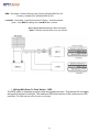
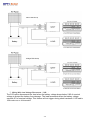
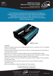
SC-10 MPPT User Manual
ELECTRICAL SPECIFICATIONS
Efficiency Typical
Input Voltage
Output Voltage (Float)
Output Voltage (Bulk)
Output Power
Quiescent Current
96%
16V to 55V
13.5V / 27V
Flooded 14.5V / 29V
Sealed 14.2V / 28.4V
Peak 250W
constant 200W @29V
constant 150W @ 14.5V
0.04A
Important:
Use only PV systems with open circuit voltage below 55V & a minimum VMP of 17V for 12V and
34V for 24V Charging.
Use wires suitable for at least 15A, but if wire runs are over 3m then larger wires are
recommended to limit voltage drop and losses.
Install the unit in a dry place out of direct sunlight and away from flammable liquids or gases.
Battery fuse (BF) is always required and must be located as close to the battery as possible,
its sizing depends on the wire size and load ratings. Typically a 15A 24V fuse would do.
Before connecting battery always check battery and PV panel polarity.
When used with panels over 150W @ 12V or 200W @ 24V the SC-10 MPPT MUST be fitted
with the PVF fuse. Locate this fuse as close as possible to the MPPT. A 10A 60V fuse is
recommended.
For optimal power output the following panel combinations are recommended:12V Charging
· 2 x 12V Battery Panels connected in series (Total VOC =42V & VMP =32V)
· 1 x 24V Battery Panel (Total VOC =42V & VMP =32V)
· 1 x 48 Cell Grid Panel (Total VOC =28V & VMP =23V)
· 1 x 54 Cell Grid Panel (Total VOC =32V & VMP =26V)
· 1 x 52 Cell Grid Panel (Total VOC =31V & VMP =25V)
· 1 x 60 Cell Grid Panel (Total VOC =36V & VMP =29V)
· 1 x 72 Cell Grid Panel (Total VOC =44V & VMP =36V)
24V Charging
· 1 x 72 Cell Grid Panel (Total VOC =44V & VMP =36V)
Note: This unit can be directly power (without a battery)
a 12VDC motor or pump of up to 100W.
General Information:
Green LED flashing – battery charging and all normal.
Red LED flashing – battery voltage low, below 0.9 of nominal voltage.
This MPPT is designed to auto detect 12V and 24V battery systems and select a suitable
charge regime.
The absorption phase is entered following a low battery condition and is maintained for
approx. 1.5 hours.
This MPPT has a built in multilevel over temperature protection to improve product reliability
while maximising output power availability.
The SC-10 MPPT will efficiently charge 12V batteries from 24V panels.
The panel voltage limits for the SC-10 MPPT are: Maximum open circuit voltage below 55V.
Minimum Maximum Power Point (at the maximum operating temperature) must be above
17V for 12V batteries and 34V for 24V batteries to ensure full power.
If used, this fuse is optional, locate the output fuse (OF) as close to the MPPT as possible
(15A 24VDC rating).
Settings And Configurations:
The SC-10 MPPT factory default setting is for sealed lead acid batteries (Maximum charge voltage
14.2V and float voltage 13.4V) and auxiliary switch (“Load-”) configured in Low Voltage
Disconnect mode. The various operating modes can be configured with a combination of the REN and
Load R/C of the front plastic cover and the switches of the rear plastic cover.
Always insure that the switch is set for the correct battery type.
The REN and Load R/C are either left unconnected (Insure they are insulated from any other point), or
grounded (shorted to the PV-&bat-).
1: All Night DDS.
2: LVD.
3: 6 Hour DDS.
4: Vented Batteries.
5: Flooded Batteries
2 /8
REN : Grounded - Enable Remote Load Control & Disable DDS & LVD,
: Floating - Disable RLC & Enable DDS & LVD.
Load R/C : Grounded - Load Disconnected, Floating - Load Connected.
Note : If the REN is floating, the Load R/C has no effect.
Basic Wiring With Permanent Load Connection:
Note: First start up may take up to one minute.
◎ Wiring With Dawn To Dusk Switch(DDS):
The DDS option is intended to power loads during darkness only. This feature will not trigger
during short periods of low light. The maximum DDS load current is 10A continuous or 20A
transients. The DDS can be set to 6 hours or all night.
3 /8
◎ Wiring With Low Voltage Disconnect(LVD):
The LVD option disconnects the load when the battery voltage drops below 0.85 of nominal
voltage to protect the battery from damage. The load reconnects when the battery voltage
exceeds 0.9 of nominal voltage. This feature will not trigger during short transients. LVD load is
10A continuous or 20A transient.
4 /8
◎ Wiring With Critical And Non Critical Loads:
Critical loads are generally light loads which are powered under any condition. Non critical loads are
loads which can be disconnected to ensure maximum on time for critical loads as well as to extend
the life expectancy and reliability of the system. The non critical load can be set up as LVD, DDS 6
hours or DDS all night with the same DDS configuration detailed earlier.
5 /8
◎ Wiring The Remote Alarm:
The remote alarm is a normally low, 5V digital signal that goes high when the battery voltage drops
below 0.9 of nominal voltage, the LVD disconnects or over temperature trips. It has a 5mA source
capability and can be used to remotely monitor system status.
CON1 P5 or P6
◎ Wiring With Load Remote Control:
This option enables the remote load connection and disconnection via the REN, Load R/C.
When the Load R/C is grounded the load is disconnected otherwise the load is connected. To
configure this mode the REN must be grounded. This option overrides the LVD or DDS function but
has the same load limitations of 10A continuous or 20A transient.
Please ensure that your MPPT has been correctly configured (DDS & BAT. settings) for your
application. Refer to the Settings and Configurations section for more information.
6 /8
MPPT FAQs
Q: What is an MPPT?
MPPT stands for Maximum Power Point Tracker and is a specialised converter designed to maintain the PV voltage at the level
in which it delivers maximum power to the load or battery. The nominal panel output power can only be ensured with the use of
an MPPT.
Q: What are the GSL MPPTs advantages compared to standard solar regulators?
1. Suitable for new lower cost high efficiency grid type panels since the MPPT can efficiently charge the batteries from relatively
high voltage, say 12V batteries from 36V MPP panels.
2. Less interference and more accurate voltages during absorption and float.
Q: What output can I expect from a 150W or 200W MPPT?
1. The maximum bulk charge current with a 12V battery and 150W panel is approximately 12A, so you can expect about 40AH
per day which is a 40W load for about 10 hours.
2. The maximum bulk charge current with a 24V battery and a 200W panel is about 8A so you can expect about 30AH which is
a 40W load for about 15 hours.
Q: Why are MPPT used mainly in high power systems?
Until now and despite their overwhelming advantages MPPTs have been excluded from low power systems because of cost.
The new MPPT specifically designed for low power makes economic sense even in small systems.
Q: What sort of batteries should I use?
1. A deep cycle battery is a must due to the cyclical nature of solar systems with a recommended battery capacity of at least
60AH.
2. A larger battery will not only give longer run time during low light but also will be able to avoid available PV power being
unstored such as when the battery reaches the float stage.
Q: How does PV temperatures affects charge current?
Temperature increase brings down the PVs maximum power point voltage reducing the MPPTs current gain available. In
principle at 25C it is possible to achieve 30% gain but at 40C (A more realistic average temperature) about 20% is still available.
Q: What happens at low PV currents?
The MPPT will outperform the conventional regulator above 4% of nominal panel power. Below 4%, 6W in a 150W panel, the
MPPT will have a slightly lower output current than a non MPPT.
Q: Is interference possible? and If so what do I do?
MPPTs produce far less interference than conventional solar regulator during the absorption and float stages, that is during
most of its operating time, and its designed to comply with local and international EMI standards however some interference is
still possible. If interference occurs first try and reorient the aerial or move the sensitive equipment away from the MPPT wires.
Ensure the MPPT chassis is grounded. Grounding a battery terminal may also help and finally you can try adding ferrite clamps.
7 /8
MECHANICAL SPECIFICATIONS
◎Drawing & Dimensions:
◎Connector Types & Pin Assignments:
Connctor
Number
Pin
Number
Connector Type
Pin 1~Pin 2
Pin 3~Pin 4
Pin 5~Pin 6
Pin 7~Pin 8
CON1
DINKLE#EHK381V or Equivalent
CON2
JST#S 3B-PH-K-S or Equivalent
Mating Connector=JST#PHR- 3 or Equivalent
8 /8
Pin 3
Pin 2
Pin 1
Signal
LOADBAT.+
PV-&BAT.PV+
Remote Alarm
Load Remote Control
REN