1
Onboard BMC/IPMI
User's Guide
Revision 1.0a
The information in this User’s Manual has been carefully reviewed and is believed to be accurate.
The vendor assumes no responsibility for any inaccuracies that may be contained in this document,
makes no commitment to update or to keep current the information in this manual, or to notify any
person or organization of the updates. Please Note: For the most up-to-date version of this
manual, please see our web site at www.supermicro.com.
Super Micro Computer, Inc. ("Supermicro") reserves the right to make changes to the product
described in this manual at any time and without notice. This product, including software, if any,
and documentation may not, in whole or in part, be copied, photocopied, reproduced, translated or
reduced to any medium or machine without prior written consent.
IN NO EVENT WILL SUPER MICRO COMPUTER, INC. BE LIABLE FOR DIRECT, INDIRECT,
SPECIAL, INCIDENTAL, SPECULATIVE OR CONSEQUENTIAL DAMAGES ARISING FROM THE
USE OR INABILITY TO USE THIS PRODUCT OR DOCUMENTATION, EVEN IF ADVISED OF
THE POSSIBILITY OF SUCH DAMAGES. IN PARTICULAR, SUPER MICRO COMPUTER, INC.
SHALL NOT HAVE LIABILITY FOR ANY HARDWARE, SOFTWARE, OR DATA STORED OR USED
WITH THE PRODUCT, INCLUDING THE COSTS OF REPAIRING, REPLACING, INTEGRATING,
INSTALLING OR RECOVERING SUCH HARDWARE, SOFTWARE, OR DATA.
Any disputes arising between manufacturer and customer shall be governed by the laws of Santa
Clara County in the State of California, USA. The State of California, County of Santa Clara shall
be the exclusive venue for the resolution of any such disputes. Supermicro's total liability for all
claims will not exceed the price paid for the hardware product.
FCC Statement: Refer to Supermicro's web site for FCC Compliance Information.
California Best Management Practices Regulations for Perchlorate Materials: This Perchlorate
warning applies only to products containing CR (Manganese Dioxide) Lithium coin cells. “Perchlorate
Material-special handling may apply. See www.dtsc.ca.gov/hazardouswaste/perchlorate”.
WARNING: Handling of lead solder materials used in this
product may expose you to lead, a chemical known to
the State of California to cause birth defects and other
reproductive harm.
Manual Revision 1.0a
Release Date: Jan. 15, 2010
Unless you request and receive written permission from Super Micro Computer, Inc., you may not
copy any part of this document.
Information in this document is subject to change without notice. Other products and companies
referred to herein are trademarks or registered trademarks of their respective companies or mark
holders.
Copyright © 2010 by Super Micro Computer, Inc.
All rights reserved.
Printed in the United States of America
Preface
Preface
About this User's Guide
This user guide is written for system integrators, PC technicians and
knowledgeable PC users who intend to configure the IPMI settings supported by
the Nuvoton WPCM450 BMC Controller embedded in Supermicro's motherboards.
It provides detailed information on how to configure the IPMI settings provided by
the Nuvoton WPCM450 chip.
Note: Nuvoton Technology is a subsidiary of Winbond Corp.
User's Guide Organization
Chapter 1 provides an overview on the Nuvoton WPCM450 Controller chip. It also
introduces the IPMI, its features and functionality.
Chapter 2 provides detailed instructions on how to configure the IPMI settings
supported by the embedded WPCM450 Controller.
Chapter 3 provides the answers to frequently asked questions.
Conventions Used in the User's Guide
Special attention should be given to the following symbols for proper installation and
to prevent damage done to the components or injury to yourself.
Warning: Important information given to prevent erroneous RAID configuration and to ensure proper system setup.
Note: Additional Information given to ensure correct RAID configuration
setup.
iii
Onboard BMC/IPMI User's Guide
Contacting Supermicro
Headquarters
Address:
Tel:
Fax:
Email:
Web Site:
Europe
Address:
Tel:
Fax:
Email:
Asia-Pacific
Address:
Super Micro Computer, Inc.
980 Rock Ave.
San Jose, CA 95131 U.S.A.
+1 (408) 503-8000
+1 (408) 503-8008
[email protected] (General Information)
[email protected] (Technical Support)
www.supermicro.com
Super Micro Computer B.V.
Het Sterrenbeeld 28, 5215 ML
's-Hertogenbosch, The Netherlands
+31 (0) 73-6400390
+31 (0) 73-6416525
[email protected] (General Information)
[email protected] (Technical Support)
[email protected] (Customer Support)
Super Micro Computer, Inc.
4F, No. 232-1, Liancheng Rd.
Chung-Ho 235, Taipei County
Taiwan, R.O.C.
+886-(2) 8226-3990
+886-(2) 8226-3991
www.supermicro.com.tw
Tel:
Fax:
Web Site:
Technical Support:
Email:
[email protected]
Tel:
886-2-8228-1366, ext.132 or 139
iv
Preface
Notes
v
Onboard BMC/IPMI User's Guide
Table of Contents
Preface
Chapter 1 Introduction
1-1
An Overview of the Nuvoton WPCM 450 BMC Controller ............................. 1-1
WPCM450 DDR2 Memory Interface ............................................................... 1-1
WPCM450 PCI System Interface.................................................................... 1-1
Supermicro IPMI Features .............................................................................. 1-2
1-2
WPCM450 Block Diagram .............................................................................. 1-3
1-3
A Brief Introduction to the IPMI ....................................................................... 1-3
1-4
Motherboards Supported ................................................................................ 1-4
1-5
An Important Note to the User ........................................................................ 1-4
Chapter 2 Configuring the IPMI Settings
2-1
Configuring the IP/MAC Addresses ................................................................ 2-1
Using the IPMICFG Utility to Set the IP/MAC Addresses ............................. 2-1
Using the BIOS Settings to set the IP/MAC Addresses ................................. 2-2
Accessing the BMC ......................................................................................... 2-3
Using the Internet Browser ............................................................................. 2-3
2-2
Using IE* to Access the BMC/IPMI Settings from Your Computer ................. 2-4
To Log In ......................................................................................................... 2-4
2.2.1 Overview ................................................................................................ 2-5
2.2.2 System Information ................................................................................ 2-6
2.3 Server Health ............................................................................................ 2-8
2.4 Configuration ........................................................................................... 2-12
2.5 Remote Control - the Main Menu ........................................................... 2-25
2.6 Virtual Media ........................................................................................... 2-49
2.7 Maintenance............................................................................................ 2-51
2.8 Miscellaneous ......................................................................................... 2-55
Chapter 3 Frequently Asked Questions
3-1
Frequently Asked Questions ........................................................................... 3-1
vi
Chapter 1: Introduction
Chapter 1
Introduction
1-1
An Overview of the Nuvoton WPCM 450 BMC Controller
The Nuvoton WPCM450, a Baseboard Management Controller (BMC), supports 2D/
VGA-compatible Graphics cores with support of PCI interface, multi-media virtualization, and Keyboard/Video/Mouse Redirection (KVMR) modules. The WPCM450
Controller is ideal for server management platforms.
The WPCM450 interfaces with the host system via a PCI interface to communicate
with the Graphics core. It supports USB 2.0 and 1.1 for remote keyboard/mouse/
virtual media emulation. It also provides LPC interface to control Super IO functions.
The WPCM450 is connected to the network via an external Ethernet PHY module
or shared NCSI connections.
The WPCM450 communicates with onboard components via six SMBus interfaces,
Platform Environment Control Interface (PECI) buses, and General Purpose I/O
ports.
WPCM450 DDR2 Memory Interface
The WPCM450 supports a 16-bit DDR2 memory module with a speed of up to
220 MHz. The motherboard supports 128 MB of memory that is shared between
the BMC and onboard graphics card. For the best signal integrity, the WPCM450
provides point-to-point connection.
WPCM450 PCI System Interface
The WPCM450 provides 32-bit, 33 MHz 3.3V PCI interface, which is compliant with
the PCI Local Bus Specification Rev. 2.3. The PCI system interface connects to the
onboard PCI Bridge and is used by the graphics controller.
1-1
Onboard BMC/IPMI User's Guide
Supermicro IPMI Features
1. Remote KVM (graphics) console
2. Virtual Media and ISO images
3. Remote server power control
4. Remote Serial over LAN (text console)
5. Event Log support
6. Automatic Notification and Alerts (SNMP and email)
7. Hardware Monitoring
8. Overall health display on the main page
9. Out of band management through shared or dedicated LAN
10. Option to change LAN connection interface at Runtime
11. VLAN
12. RMCP & RMCP+ protocols supported
13. SMASH/CLP
14. Secure command line interface (SSH) and Telnet
15. WSMAN and WS-CIM
16. RADIUS authentication support
17. Secure browser interface (Secure socket layer - SSL support)
18. Lightweight Directory Access Protocol (LDAP) supported
19. DCMI 1.0 support
20. Back up and restore configuration file
21. Factory defaults from web support
22. Video quality settings
23. Record video and play
24. Server data/information
25. Preview of the remote screen on the main page
26. Update Firmware through browser and OS
27. OS independent
1-2
Chapter 1: Introduction
1-2
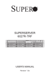
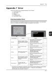
WPCM450 Block Diagram
The following diagram represents a typical system setup for the WPCM450 Controller.
1-3
A Brief Introduction to the IPMI
PROCESSOR
PCI-E
PECI
USB
2.0
USB
1.1
PCI
LPC
Wake-up & CTRL
South Bridge
RMII
Serial Port
WPCM450
RMII
VGA
SPI
Sensors
Ethernet CTRL
Onboard LAN1
RS232
PHY
RJ45
Serial Port
RJ45
Dedicated LAN
NOR Flash
DDR2
The Intelligent Platform Management Interface (IPMI) Specification defines a set of
common interfaces to a computer system that provides remote access to multiple
users from different locations for networking. It also allows a system administrator
to monitor system health and to manage the computer events remotely.
IPMI operates independently of the operating system. When used in conjunction with
the IPMIView, an IPMI-compliant management application software loaded into a
PC computer, the WPCM450 BMC Controller, embedded onto a server board, provides serial link connections between the South Bridge and other onboard system
components, allowing for network interfacing via remote access. With WPCM450
Controller and the IPMIView software built in, the Supermicro motherboard allows
a user to access, monitor, diagnose and manage a computer system from a remote
site. It also provides remote access to multiple users from different locations for
system maintenance and management.
1-3
Onboard BMC/IPMI User's Guide
1-4
Motherboards Supported
This version of Onboard BMC/IPMI is supported by the motherboards listed in the
table below. If your motherboard is not included in the table, please refer to the
motherboard product page on our web site @www.supermicro.com and download
the right BMC/IPMI user's guide for your motherboard.
Motherboards supported (for -F models only)
X8DTL Series
X8SIE Series
X8SIL Series
H8DGU+ Series
1-5
An Important Note to the User
The graphics shown in this user's guide were based on the latest information
available at the time of publishing of this guide. The IPMI screens shown on your
computer may or may not look exactly like the screen shown in this user's guide.
1-4
Chapter 2: Configuring BMC/IPMI Settings
Chapter 2
Configuring the IPMI Settings
With the Nuvoton WPCM450 BMC Controller chip built in, the Supermicro motherboard allows the user to access, monitor, manage and interface with systems in
remote locations. The necessary utilities for accessing and configuring the IPMI
settings are available on the Supermicro Website at hppt://www.supermcro.com/
products/nfo/ipmi.cfm. This section provides detailed information on how to configure the IPMI settings.
2-1
Configuring the IP/MAC Addresses
Note: The DHCP (Dynamic Host Configuration Protocol) is on by default.
To change the manufacturer default setting, please use the ipmicfg utility
or BIOS.
Using the IPMICFG Utility to Set the IP/MAC Addresses
1. Run the ipmicfg utility from the bootable CD that came with your shipment.
2. Follow the instructions given in the Readme.txt file to configure Gateway IP/
Netmask IP addresses, to enable/disable DHCP and to configure other IPMI
settings.
IPMICFG Version 1.14 (Build 080711) Copyright 2008 Super Micro Computer, Inc.
Usage: IPMICFG Parameters (Example: IPMICFG -m 192.168.1.123)
-m
Shows IP and MAC
-m IP
Sets IP (format: ###.###.###.###)
-a MAC
Sets MAC (format: ##:##:##:##:##:##)
-k
Shows Subnet Mask
-k Mask
Sets Subnet Mask (format: ###.###.###.###)
-dhcp
Gets the DHCP status
-dhcp on
Enables the DHCP
-dhcp off
Disables the DHCP
-g
Shows Gateway IP
-g IP
Sets Gateway IP (format: ###.###.###.###)
-r
BMC cold reset
-garp on
Enables the Gratuitous ARP
2-1
Onboard BMC/IPMI User's Guide
-garp off
Disables the Gratuitous ARP
-fd
Resets to the factory defaults
-ver
Gets the firmware revision
-vlan
Gets VLAN status
-vlan on (VLANtag)
Enables the VLAN and sets the VLAN tag (If VLAN
tag is not given, it uses previously saved value.)
-vlan off
Disables the VLAN
-raw
Sends a RAW IPMI request and print the response.
Format: NetFn LUN Cmd [Data1...DataN].
-sdr
Shows SDR records and reading
-sdr del <SDR ID>
Deletes SDR record
-sdr backup <FILE>
Backups SDR to file
-sdr restore <FILE>
Restores SDR from file
-sdr ver [<V1><v2>]
Retrieves and sets SDR version (V1, V2)
-sel info
Shows SEL info
-sel list
Shows SEL records
-sel del
Deletes all SEL records
-fru info
Shows FRU inventory area info
-fru list
Shows all FRU values
-fru help
Shows FRU Write help
-fru cthelp
Shows chassis type code
-fru <Field>
Shows FRU field value
-fru <Field> <Value>
Writes FRU
-fru backup <File>
Backs up FRU to file
-fru restore <File>
Restores FRU from file
-fru ver [<V1> <V2>]
Retrieves and sets FRU version (V1, V2)
Using the BIOS Settings to set the IP/MAC Addresses
1. Go to the BIOS by pressing the <Del> key during system boot.
2. Select IPMI from the Advanced Menu.
3. Select LAN Configuration from the IPMI submenu.
4. Click on the item - IP Address Source. Select "Static" and press <Enter>. The
onboard BIOS will automatically set the IP Address, MAC Address, Gateway,
and Subnet Mask.
2-2
Chapter 2: Configuring BMC/IPMI Settings
5. Once the IP, MAC Addresses, Gateway and Subnet Mask are set, click <Update LAN Settings>. Select Yes and press <Enter> to update the IPMI LAN
settings.
6. Go to the Exit menu. Select Save Changes & Exit and press <Enter> to save
changes and exit the BIOS.
Accessing the BMC
1. Connect a LAN cable to the onboard LAN1 port or the dedicated IPMI LAN
port.
2. Choose a computer that is connected to the same network and open the
IPMIView utility.
3. Go to File>New>System. Enter System Name, IP Address of LAN1 or the
dedicated LAN, and Description in the appropriate fields and press <Enter>.
4. Select the system from the IPMI Domain. Enter the Login ID and Password in
the appropriate fields to log in to the IPMIView utility.
Using the Internet Browser
1. Connect a LAN cable to the onboard LAN1 port or the dedicated IPMI LAN
port.
2. Choose a computer that is connected to the same network and open the
browser.
3. Enter the IP address of each server that you want to connect to in the address bar in your browser.
4. Once the connection is made, the Log-In screen as shown on the next page
will display.
Note: The default network setting is "Failover", which allows the IPMI to
connect to the network through a shared LAN port (onboard LAN Port 1
or eth0) or through the IPMI_Dedicated_LAN_Port. If the IPMI must be
connected through a specific port, please change the LAN Configuration
under the Network Settings.
2-3
Onboard BMC/IPMI User's Guide
2-2 Using IE* to Access the BMC/IPMI Settings from
Your Computer
To Log In
Once you are connected to the remote server, the following screen will display.
1. Enter your Username in the "Username" box.
2. Enter your Password in the "Password" box and click "Login."
3. The Home Page will display as follows.
Note 1: To use the IPMIView utility to access the BMC/IPMI settings, please refer
to the IPMIView User's Guide for instructions.
Note 2: The manufacturer default username and password are ADMIN/ADMIN.
Once you have logged into the BMC using the manufacturer default password,
be sure to change your password for security purpose.
Note 3: The "Administrator" account cannot be deleted.
2-4
Chapter 2: Configuring BMC/IPMI Settings
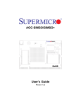
2.2.1 Overview
Once you are logged in the IPMI utility, the IPMI Main page will display the status
of system information.
1
1. Overall System Status
This screen displays a summary of current system health conditions. It indicates
the overall system health based on the sensor readings on temperatures, voltages,
fans, and the chassis.
•
When a critical condition occurs, the display will be in color red (critical);
•
When a warning state occurs in a sensor, but there are no critical conditions on
other sensor, the display turns to yellow.
•
If there is no warning or critical condition occurs, and the system is normal, the
display will become green.
2-5
Onboard BMC/IPMI User's Guide
2.2.2 System Information
Once you are logged in the IPMI utility, the IPMI Main page will display the following system information.
3
1
2
4
The IPMI page contains a submenu bar (#1), the Options window (#2), the languages settings (#3), and the main display area (#4). The first main page displays
system information.
1. The Submenu Bar
The submenu bar on the top lists the status of the IPMI connection and the following submenus:
•
System Information: This submenu displays system information.
•
Server Health: This submenu displays server health monitoring status.
•
Configuration: This submenu allows the user to configure the IPMI settings.
•
•
Remote Control: This submenu allows the user to launch KVM Console and
perform power control & Management.
Virtual Media: This submenu allows the user to configure Virtual Media settings
for the remote console.
•
•
Maintenance: This submenu allows the user to update firmware and reset the
unit.
Miscellaneous: This submenu allows the user to post snooping codes and to
launch the SOL console.
2-6
Chapter 2: Configuring BMC/IPMI Settings
2. Options
The Options window on the left side allows the user to navigate through different
options, including the following:
•
System Information: Click this item to display Firmware Revision# and Build
Time
•
FRU Reading: Click this item to display the status of the BMC FRU (Field
Replaceable Unit).
•
Refresh Page: Click this icon to refresh the page.
•
Logout: Click this icon to logout from the IPMI utility.
3. Language
Form the Language pull-down submenu, select the following language settings:
•
English
•
Japanese
4. The Main Display Area
This area displays the following system information:
•
•
•
•
Firmware Revision: This item displays the firmware revision number.
Firmware Build Time: This item displays time and date when the firmware
was built.
FRU Revision: This item displays the FRU (Field Replaceable Unit) revision
number.
SDR Revision: This item displays the revision number for the SDR (Sensor
Data Record.)
•
IP Address: This item displays the IP address of the BMC.
•
MAC Address: This item displays the MAC address of the BMC.
2-7
Onboard BMC/IPMI User's Guide
2.3 Server Health
This feature allows the user to set Server Health Settings. When you click the Server
Health icon (#1) on the submenu bar, the following screen will display:
1
2
3
The Server Health submenu includes Sensor Readings (#2), and Event Log (#3)
as shown on the main display area.
Click the item "Sensor Reading" (#2) on the main area to display its menu as
shown below.
5
6
9
4
7
8
2.3.1. The Categories of Sensor Types (#4)
The categories of sensor type includes the following:
•
All Sensors: This item displays the readings for all sensors
•
Temperature Sensors: This item displays the reading and the status of system
temperature and system components.
2-8
Chapter 2: Configuring BMC/IPMI Settings
•
Voltage Sensors- This item displays the voltage reading of the system or a
component.
•
Fan Sensors- This item displays the status of an onboard fan.
•
Physical Security/(Chassis Intrusion): This item displays the status of chassis intrusion.
•
Power Supply: This item displays the status of power supply.
•
OEM Reserved: This item displays the status of an item defined by an OEM.
2. Status (#5)
This category displays the status of each sensor item.
3. Reading (#6)
This category displays the sensor reading of each item.
4. Refresh (#7)
Click this button to refresh the page.
5 Show Thresholds (#8)
Click this bottom to display the thresholds of sensor items.
6. Sensor Readings (#9)
This item displays the number of items that are monitored by the firmware.
2.3.1 Sensor Readings Display-All Sensors
When you select All Sensors (#1) from the Sensor Type Category pop-up submenu,
the sensor readings for the following items will be displayed as shown below.
2-9
Onboard BMC/IPMI User's Guide
1
•
•
•
Fan1~Fan8: This item displays the status and the RPM reading of each onboard fan.
CPU Temperature: This item displays the status of the CPU temperature.
System Temperature: This item displays the status of the system temperature.
•
CPU1 Voltage/CPU2 Voltage
•
1.5v Voltage
•
+5v Voltage/+5VSB Voltage
•
+12 Voltage/-12 Voltage
•
+3.3 Voltage/+3.3VSB Voltage
•
Battery Voltage
•
CPU1 Temperature/CPU2 Temperature
•
System Temperature
•
•
Chassis Intrusion: This item displays the status of chassis intrusion to indicate
the security setting of the system.
Select a Sensor Type Category: This feature allows the user to select a specific sensor display. The submenu items include: Temperature Sensor, Voltage,
Fan, Physical, Power and OEM.
2-10
Chapter 2: Configuring BMC/IPMI Settings
2.3.6. Event Log
This feature allows the user to configure the Event Log settings. Select "Event Log"
(#1) in the Options Window and press <Enter> to display the following screen.
1
2
The Event Log Categories displayed in the pull-down submenu include:
•
•
•
Sensor-Specific Events: This item displays the event log for sensor-specific
events.
BIOS-Generated Events: This item displays the event log for BIOS-generated
events.
System Management Software Events: This item displays the event log for
system management software events.
2-11
Onboard BMC/IPMI User's Guide
2.4 Configuration
This feature allows the user to configure various network settings. When you click
the Configuration icon (#1) on the submenu bar, the following screen will display:
1
2
3
The Configuration submenu includes the items displayed in the Options window on
the left (2) or in the Main Display area on the right (3).
Select an item on the list to configure its settings.
Alerts
•
•
Date & Time
•
LDAP
•
Radius
•
Mouse mode
•
Network
•
Dynamic DNS
•
Remote Session
•
SMTP
•
SSL Certificate
•
Users
Note: To set up an email alert, please enter the IP address of your mail
server in the SMTP (Simple Mail Transfer Protocol) format.
2-12
Chapter 2: Configuring BMC/IPMI Settings
2.4.1.1 Configuration - Alerts
This feature allows the user to configure Alert settings. When you click the Alerts
icon in the Options window (1), the following screen will display.
1
2
3
4
2. Modify: Click \the Modify icon to configure or modify a selected alert.
3. Send Test Alert: Click this icon to send a configured alert to its destination (the
target address) for testing/debugging.
4. Delete: Click this icon to delete an alert.
2-13
Onboard BMC/IPMI User's Guide
2.4.1.2 Configuration - Modify Alerts
This feature allows the user to modify Alert settings. When you click the Alerts icon
in the Options window (1), the following screen will display.
1
2
3
4
5
6
1. To modify an alert, enter the information needed for the following items:
2. Event Severity: This item allows you to decide how to classify or label an alert
according to the seriousness of the alert. You can choose an item from the
pop-up menu to categorize the alert: Disable All, Informational, Warning, Critical or Non-recoverable.
3. Destination IP: This item allows you to specify the IP address of the server
that you want to send your alert to.
4. Email Address: This item allows you to specify the email address that you
want to send your alert to.
5. Subject: Use this item to enter the subject of the alert.
6. Message: Use this item to enter a message to the recipient of the email.
After entering all needed information in the fields, press <Save> to save the information you've entered or press <Cancel> to cancel it.
Note: To set up an email alert, please enter the IP address of your mail
server in the SMTP (Simple Mail Transfer Protocol) format.
2-14
Chapter 2: Configuring BMC/IPMI Settings
2.4.2 Configuration - Time and Date Settings
This feature allows the user to configure the time and date settings for the host
server and client computer. When you click the Time and Date icon in the Options
window (1), the following screen will display.
2
3
4
5
6
7
1
1. Time and Date: Click on this item to configure the Time and Date settings.
2. Time Zone: Select the correct local time zone from the pull-down menu based
on the Coordinated Universal Time standard (UTC). This option is enabled when
NTP is selected. (The options are UTC-12:00 hr. ~ UTC+12:00 hr.)
3. NTP Server: Check the Enable box to enable NTP server. Check Disable to
disable the NTP Server.
4. Primary NTP Server: Enter the IP Address of the primary NTP server.
5. Secondary NTP Server: Enter the IP Address of the secondary NTP server.
6. Date: Select the correct month/date/year from the pull-down menu
7. Time: Enter the correct time in the (hh/mm/ss) format in the time fields.
2-15
Onboard BMC/IPMI User's Guide
2.4.3 Configuration - Light-Weight Directory Access Protocol
(LDAP) Settings
This feature allows the user to configure the Light-Weight Directory Access Protocol
(LDPA) settings. When you click the LDAP icon in the Options window, the following
screen will display.
1
2
3
4
5
6
1. Check the enable box to enable LDAP Authentication support.
Examples and Explanations of the LDAP settings are shown below:
2. Port-This item indicates the port number of the LDAP server.
3. IP Address: xx.xx.xx.xx- This item indicates the IP address of the LDAP
server.
4.Bind Password: Secret- This item indicates the password for the LDAP server.
5. Bind DN: cn=manager, dc=administrator, dc=com-The bind DN is the user or the
LDAP server that is permitted to do search in the LDAP directory within a defined
search base.
6. SearchBase: dc=administrator, dc=com-The research base shows the client
which port in the external directory tree to search.
After entering the information in the fields, click Save to save the information you've
entered.
2-16
Chapter 2: Configuring BMC/IPMI Settings
2.4.4. Configuration - Radius Option Settings
This feature allows the user to configure the Radius Option settings. When you click
Radius in the Options window, the following screen will display.
1
2
3
4
1. Check the enable box to enable Radius Option support.
2. Port -This item indicates the port number of the Radius server.
3. IP Address: xx.xx.xx.xx- This item indicates the IP address of the Radius
server.
4. Secret- This item indicates an access password to the Radius server
After entering the information in the fields, click Save to save the information you've
entered.
2-17
Onboard BMC/IPMI User's Guide
2.4.5 Configuration - Mouse Mode Settings
This feature allows the user to configure the mouse mode settings. When you click
the Mouse Mode icon in the Options window (1), the following screen will display.
2
3
1
1. Mouse Mode: Click on this icon to configure the mouse mode setting.
2. Set Mode to Absolute: Check the radio button to use the Absolute mode for the
Windows OS. (This is the default setting.)
3. Set Mode to Relative: Check the radio button to use the Relative mode for the
Linux/Unix OS.
Note: IPMI is an OS-independent platform, and KVM support is an added
feature for IPMI. For your mouse to function properly, please configure the
Mouse Mode settings (above) according to your OS type.
2-18
Chapter 2: Configuring BMC/IPMI Settings
2.4.6 Configuration - Network Settings
This feature allows you to configure the network settings. When you click the Network icon in the Options window (1), the following screen will display.
2
3
4
5
6
7
8
1
9
10
1. Network: This item allows you to view or modify network settings.
2. MAC Address: Enter the MAC address for networking in the box.
Check the first radio button to obtain an IP address automatically by using DHCP
(Dynamic Host Configuration Protocol). (Note: DHCP is the default setting.) Check
the second radio button to use the IP address entered below.
3. IPv4 Setting: This item allows the user to set the IP address using the IPv4
format.
4. IP address: If the second radio button above is checked, please enter your IP
address in the box.
5. Subnet Mask: Enter the address for the subnet mask of your network.
6. Default Gateway: Enter the IP address for the default gateway of your network.
7. DNS Server IP: Enter the IP address of your domain name server.
8. IPv6 Setting: This item allows the user to set the IP address using the IPv6
format.
9. Enable VLAN: Check this box to enable Virtual LAN support.
10. LAN Interface: Click this item to display the LAN Interface sub-items.
•
Dedicate: If this is selected, IPMI will connect through the IPMI Dedicated port
LAN only.
•
Share: If this is selected, IPMI will connect through LAN1 on the board.
•
Failover (Default): If this is selected, IPMI will connect through Shared or Dedicated LAN. If a connection fails, IPMI will switch to the other provided that the
cable is plugged in.
2-19
Onboard BMC/IPMI User's Guide
2.4.7 Configuration - Dynamic DNS Settings
This feature allows you to configure network settings. When you click the Dynamic
DNS icon in the Options window (1), the following screen will display.
2
3
4
5
6
1
1. Dynamic Domain Name Server (DNS): This item allows you to view or modify
the Dynamic DNS settings.
2. Dynamic Update Enable/Disable: Click the Enable radio button to enable Dynamic DNS update support; click Disable button to disable Dynamic DNS update
support. (Default: Disable)
3. Dynamic DNS Server IP: Enter the IP address of your Dynamic DNS IP address.
4. BMC Hostname: Enter the name of the BMC (Baseboard Management Controller) Host Server.
5. TSIG.key File: Browse the file to select the TSIG.key file. This item is optional.
6. TSIG.private File: Browse source files to select the TSIG.private file. This item
is optional.
After entering the required information in the fields, click <Save> to save the information you have entered.
2-20
Chapter 2: Configuring BMC/IPMI Settings
2.4.8 Configuration - Remote Session
This feature allows the user to configure remote session settings. When clicking the
Remote Session in the Options window (1), the following screen displays.
2
1
2. Virtual_Media_Attach_Mode: Click the pull-down menu to display the following virtual media attach modes:
•
Auto Attach (Default): Select this mode to automatically enable virtual media
support and make it available for remote access. Virtual devices will only be
shown in the operating systems and the BIOS when a device or an ISO image
is connected through the virtual media wizard.
•
Attach: Select this mode to activate a virtual media in order to make it available
for remote access. A virtual device will always be seen in the system BIOS even
when it is not active.
•
Detach: Select this mode to disable virtual media for remote access.
Warning: Be sure to close all Java sessions before changing floppy
emulation to avoid unexpected errors.
2-21
Onboard BMC/IPMI User's Guide
2.4.9 Configuration - SMTP Settings
This feature allows the user to configure SMTP (Simple Mail Transfer Protocol)
settings for email transmission through the network. When you click the SMTP icon
in the Options window (1), the following screen will display.
2
3
4
5
1
2. SMTP Server: Enter the IP address for the SMTP (Simple Mail Transfer Protocol)
Mail server, and press <Save>.
3. SMTP Port Number: Enter the port number for your SMTP (Simple Mail Transfer
Protocol) Mail server, and press <Save>.
4. SMTP User Name: Enter the user name for your SMTP (Simple Mail Transfer
Protocol) Mail server, and press <Save>.
5. SMTP Password: Enter the user's password for your SMTP (Simple Mail Transfer
Protocol) Mail server, and press <Save>.
2-22
Chapter 2: Configuring BMC/IPMI Settings
2.4.10 Configuration - SSL Settings
This feature allows the user to configure upload settings for encrypted data to transmit across the internet by using the Secure Sockets Layer (SSL) protocol. When you
click the SSL icon in the Options window (1), the following screen will display.
2
3
4
5
1
1. SSL: Check this item to configure SSL Upload settings for the encrypted data
to securely transmit through the internet.
2. Certificate Valid From: This item indicates the date when the current SSL
Certificate became valid.
3. Certificate Valid Until: This item indicates the last date when the current SSL
Certificate remains valid.
4. New SSL Certificate: This item allows the user to browse the data base to select
the new SSL Certificate. Press <Upload> to enter the new item in the field.
5. New Private Key: This item allows the user to browse the data base to select
the new private key for the SSL Certificate. Press <Upload> to enter the new item
in the field.
2-23
Onboard BMC/IPMI User's Guide
2.4.11 Configuration - Users Settings
This feature allows you to change users settings. When you click the Users icon in
the Options window (1), the following screen will display.
2
3
4
5
1
6
7
8
1. Users: Select this item to configure the user settings. The current user list is
displayed. To delete or to modify a user setting, select the name and press <Delete
User> or <Modify User>.
2. User ID: This item displays a user's ID number.
3. User Name: Use this item to enter and display a user name.
4. Network Privileges: Use this item to set the network access privileges for a
user.
•
Privileges for an Administrator: An administrator has full power in accessing,
controlling and managing the network, including creating accounts for users and
changing network configuration settings.
•
Privileges for an Operator: An operator has limited access to the network in order
to perform tasks that have been pre-assigned or approved by the Administrator.
He/she is not allowed to issue commands or modify network settings.
5. Number of configured users: This item displays the number of the users that
are set up for the network. The maximum of 16 user profiles can be made.
6. Add User: Click this icon to add a new user to the network. When prompted,
select an empty slot from the users list to add an user.
7. Modify User: Click this icon to modify the information or the status of a user.
When prompted, using the arrow keys, select a user from the users list to modify
the user information.
8. Delete User: Click this icon to delete a user from the network. When prompted,
using the arrow keys, select a user from the users list to delete it from the list.
2-24
Chapter 2: Configuring BMC/IPMI Settings
2.5 Remote Control - the Main Menu
This section allows the user to carry out activities and perform operations on a
remote server via remote access.
2
3
1
4
The Remote Access Main Menu includes the following items:
1. Remote Control: Click this icon to configure Remote Control settings.
2. (Launch) Console Redirection: Click this button to launch Console Redirection.
3. (Server) Power Control: Click this button to display server power state and to
configure server power settings.
4. (Launch) SOL: Click this button to enable Serial_Over_LAN support.
2-25
Onboard BMC/IPMI User's Guide
2.5.1 Remote Control-Console Redirection
This feature allows you to perform various activities on the server. When you click
the Console Redirection icon in the Options window (1) to activate Console Redirection settings, the following screen will display.
1
3
2
1. Console Redirection: Check this item to use console redirection and manage
the server from a remote site via Java or Active X (for the Internet Explorer).
2. Launch Console: Click this button to launch the remote console via the Java
script.
3. Java Starting: Upon launching the remote console, a screen displays, indicating that Java is starting. Once the process is completed, a screen will display as
shown below.
2-26
Chapter 2: Configuring BMC/IPMI Settings
2.5.1.1 Console Redirection - Virtual Device
This feature allows you to configure Virtual Device settings for your console redirection. When you click the Virtual Device icon in the Menu bar (1), the video settings
of the remote console will display as shown below.
1
2
3
1. Virtual Device: Click this item to configure virtual device settings of a server on
a remote site via Console Redirection.
2. Virtual Storage: Click this item to select a virtual storage device for your console
redirection. When you click on this item, the screen as shown below displays.
3. Virtual Keyboard: Click this item to configure virtual keyboard settings for your
console redirection. When you click this item, the screen on the next page display
will display.
5
4
6
7
8
2-27
Onboard BMC/IPMI User's Guide
Virtual Devices
4. USB Floppy & Flash Devices: Click this item to use a USB floppy device or a
flash device for your console redirection.
5. CDROM & ISO: Click this item to use a CDROM or an ISO device for your
console redirection.
6. Logical Drive Type: Click this item to select a logical drive type from the pulldown menu for your console redirection.
7. Image Filename and Full Path: Enter the Image Filename and the path for
your console redirection.
8. Plug In: After you've entered the correct information, click <Plug In> and <OK>
to launch console redirection.
9
Virtual Keyboard
9. Virtual Keyboard: Click the item to activate the Virtual Keyboard.
10. English Keyboard: The screen above shows the Virtual Keyboard in English.
Click a key on the keyboard for your BMC connection.
10
2-28
Chapter 2: Configuring BMC/IPMI Settings
2.5.1.2. Console Redirection - Record
This feature allows you to record media displays for your console redirection. When
you click the Record icon in the Menu bar (1), Record settings will be shown as
follows.
1
2
3
1. Record: Click this item to use the recording features for your remote server. The
features include the following.
2. Start Recording: Click this item to start video recording on your remote
server.
3. Stop Recording: Click this item to stop video recording on your remote
server.
2-29
Onboard BMC/IPMI User's Guide
2.5.1.3. Console Redirection - Playback
This feature allows you to playback the media displays that you have recorded.
When you click the Playback icon in the Menu bar (1), Playback settings will be
displayed as shown below.
1
2
3
4
5
1. Playback: Click this item to playback the media display you have recorded. The
settings include the following:
2. Open: Click this item to open your media recording files.
3. Close: Click this item to close your media recording files.
4. Stop: Click this item to stop media recording playback.
5. Play/Pause: Click this item to continue with media recording playback or to stop
media recording playback.
2-30
Chapter 2: Configuring BMC/IPMI Settings
2.5.1.4. Console Redirection - Macro
This feature allows you to configure Macro settings for your console redirection.
When you click the Macro icon in the Menu bar (1), the macro settings of the remote
console will display as shown below.
1
2
3
4
5
6
7
1. Macro: Click this item to configure the Macro settings for your remote server.
The features include the following:
2. Hold Right ALT Key: This item performs the same function as you holding down
the <Right Alt> key.
3. Hold Left ALT Key: This item performs the same function as you holding down
the <Left Alt> key.
4. Right Windows Key: This item performs the same function as you pressing
the <Right Windows> key. Right click this item to select "Hold Down" or "Press &
Release" for the <Right Windows> key.
5. Left Windows Key: This item performs the same function as you pressing the
<Left Windows> key. Right click this item to select "Press Down" or "Press & Release" for the <Left Windows> key.
6. Macro: Click this item to activate a pull-down submenu. The Macro Hotkey
submenu includes the following items as shown on the next page.
2-31
Onboard BMC/IPMI User's Guide
7. Macro Hotkeys: Click this item to display the macro hotkey pop-up submenu.
The hotkeys include the following:
•
CTRL + ALT + Del
•
ALT + Tab
•
ALT + Esc
•
Ctrl + Esc
•
ALT + Space
•
ALT + Enter
•
ALT + Hyphen
•
ALT + F4
•
ALT + Prnt Scrn
•
Prnt Scrn
•
F1
•
Alt + F1
•
Pause
2-32
Chapter 2: Configuring BMC/IPMI Settings
2.5.1.5.1. Console Redirection - Options: Hotkey Settings
This feature allows you to configure Hotkey settings for your console redirection.
When you click the Options icon in the Menu bar (1), the Options menu will display
as shown below.
1
3
2
4
6
7
5
8
2. The options menu allows you to configure the settings for Hotkey, Preference,
Full-Screen Mode, OSD UI Style and Keyboard_Mouse_Hotplug for your console
redirection.
Hotkey Settings
3. Set Hotkey: Click this item to configure your hotkey settings for your console
redirection. When you click this item, the Hotkey Settings screen displays as shown
above.
4. The Hotkey Settings screen displays the following information.
•
•
•
Hotkeys: Hotkeys: F1 ~ F7 are displayed on the right side of the screen.
Actions: Click a hot key to show the action corresponding to this hot key on
the left of the screen.
Keyboard Monitor: Click this item to enable keyboard monitor support.
5. Assign: Click a hotkey and select an action from the actions menu, and then
click Assign to assign the action to the hotkey.
6. Start: After an action is assigned to a hotkey, click Start to execute the command
and complete the assignment.
7. Stop After an action is assigned to a hotkey, click Stop to cancel the selection.
8. Close: After configuring the hotkey settings, click Close to close this submenu.
2-33
Onboard BMC/IPMI User's Guide
2.5.1.5.2. Console Redirection - Options: Preference (-Display)
This feature allows you to configure Video Recording Preference settings for your
console redirection. When you click the Options icon in the Menu bar (1), the Options menu will display as shown below.
3
1
2
4
5
6
2. Sub-items for Preference include: Display, Input, Language, Window and
Video Stream Control.
3. Display: Click <Display> to configure Video Display features.
4. Recording Time: Check this box if you want video recording to be automatically
turned off at a certain time. Once the automatic stop is select, enter the number of
minutes when your video recording will be automatically shut-off.
5. Display Scale: Use the handle on the slider to set the appropriate scale setting
for your video display (from 25 ~ 100).
6. Image Quality: Check the High Color box for a network connection with heavier
traffic. Check the Low Color box for a network connection with lighter traffic.
Click <OK> to use the settings set up by you.
2-34
Chapter 2: Configuring BMC/IPMI Settings
2.5.1.5.2. Console Redirection - Options: Preference (-Input)
1
2
3
4
5
1. Input: Click this icon to select Input settings.
2. Mouse Settings: Click <Input> to configure mouse settings, including the following.
3. Enable Mouse Input: Check this box to use your mouse as an input device for
your console redirection. Once mouse support is enabled, select Absolute Mouse
Mode if you have the Windows OS; select Relative Mouse for the Linux OS.
4. Keyboard Settings: Check this box to use the keyboard as an input device for
your console redirection. Once keyboard support is enabled, you can configure
repeat key timeout settings.
5. Repeat Key Timeout: Use the handle on the slider to select the appropriate
timeout settings for repeat keystrokes from 0ms (micro-second) to 1000ms (microsecond) .
2-35
Onboard BMC/IPMI User's Guide
2.5.1.5.2. Console Redirection - Options: Preference (-Language
Settings)
This feature allows you to configure Language Preference settings for console redirection. When you click the Options icon in the Menu bar (1), the Options menu
will display as shown below.
1
2
3
4
2. From the Preference submenu, select Language settings.
3. From the language setting pop-up menu, select the language you want to use for
your console redirection. The language options are: English, Japanese, German,
French, Spanish, Korean, and Italian.
4. Once you have selected a language to use, click <OK> to use the language.
2-36
Chapter 2: Configuring BMC/IPMI Settings
2.5.1.5.2. Console Redirection - Options: Preference (-Window)
1
2
3
1. From the Preference submenu, click <Window> to display the submenu. The
Window pop-up menu will display.
2. Check this box to allow the display window to be automatically re-sized for best
video display.
3. Click OK to keep the selection.
2-37
Onboard BMC/IPMI User's Guide
2.5.1.5.2. Console Redirection - Options: Preference (-Video Stream
Control)
1
2
3
1. From the Preference submenu, click <Video Stream Control> to display the
submenu. The Window pop-up menu will display.
2. Check this box to enable Video Stream Flow Control support.
3. Select the correct speed setting. After your speed selection, click OK to use
the setting.
2-38
Chapter 2: Configuring BMC/IPMI Settings
2.5.1.5.3. Console Redirection - Options: Full Screen Mode
This feature allows you to set the video display to the full screen mode for your
console redirection. When you click the Options icon in the Menu bar (1), the Options menu will display as shown below.
2. From the Options submenu, click <Full Screen Mode> to use the full screen
display mode for your console redirection.
1
2
3
4
2-39
Onboard BMC/IPMI User's Guide
2.5.1.5.4 Console Redirection - Options: OSD UI Style
This feature allows you to configure OSD (On-screen Display) UI (User-Interface)
Style settings for your console redirection. When you click the Options icon in the
Menu bar (1), the Options menu will display as shown below.
1
2
2. The OSD UI Style submenu: From the Options pull-down menu, click "OSD UI
Style" to display the OSD UI Style screen (#3) as shown below.
3
4
5
6
7
8
9
10
11
12
The OSD UI Style Screen Close-up
2-40
13
14
15
16
Chapter 2: Configuring BMC/IPMI Settings
3. The OSD UI Style Screen: This screen provides shortcuts to the main features
provided by the firmware for your console redirection. Click an OSD UI Style icons
to change the following settings.
4. Move OSD UI Screen: Click this icon to move the OSD UI Screen to a new
location on the display.
5. Hotkey Settings: Click this icon to access the Hotkeys submenu and change
the settings.
6. Virtual Media: Click this item to access the Virtual Media submenu and configure
the settings.
7. Virtual Keyboard: Click this item to access the Virtual Keyboard submenu and
use your virtual (soft) keyboard.
8. Preferences submenu: Click this item to access the References submenu as
indicated in the previous sections.
9. Full Screen Mode: Click this item to change the size of your display window to
the full screen mode.
10. Exit Remote Console: Click on this item to exit from the remote connection.
11. Users List: Click on this item to display the user list.
12. Change Tool Bar Display: Click this item to change the tool bar display format.
13. Hotplug Keyboard/Mouse: Click this item to use hotplug (soft) keyboard and
mouse.
14. Macro: Click this item to enable Macro support and use the features of Macro
settings.
15. Video Recording: Click this item to access the Video Recording submenu and
to use video recording.
16. Video Recording Playback: Click this item for video recording playback.
2-41
Onboard BMC/IPMI User's Guide
2.5.1.5 Console Redirection - Keyboard/Mouse Hotplug
This feature allows you to select the size of your monitor display. When you click the
Keyboard/Mouse Hotplug icon in the Menu bar (1), the submenu will display.
1
2
2. Keyboard/Mouse Hotplug: Click the item enable keyboard/mouse hotplug support for your console redirection.
2-42
Chapter 2: Configuring BMC/IPMI Settings
2.5.1.5 Console Redirection - User List
This feature allows you to access the user list. When you click the User List icon in
the Menu bar (1), the User List submenu will display as shown below.
3
4
5
1
2
2. Show User List: From the pull-down menu, click "Show User List" to display the
User List screen as shown above.
3. Session ID: This item displays the current session ID#.
4. User Name: This item displays the name(s) of the user(s).
5. IP Address: This item displays the IP Address of the host server.
2-43
Onboard BMC/IPMI User's Guide
2.5.1.5 Console Redirection - Capture
This feature allows you to capture the screen display on your remote console.
When you click the Capture icon in the Menu bar (1), the Capture submenu will
display as shown below.
1
2
2. Full Screen Capture: Click this item to capture the full screen video display. for
your remote console.
2-44
Chapter 2: Configuring BMC/IPMI Settings
2.5.1.6 Console Redirection - Exit
When you click the Exit icon in the Menu bar (1), the Exit submenu will display as
shown below.
1
2
2. Exit: Click <Exit> to exit from the current session of console redirection. The
following screen will display.
3
4
3. Yes: At the prompt- "Are you sure?", click Yes to exit from remote redirection.
4. No: Click No to return to the current session of remote redirection.
2-45
Onboard BMC/IPMI User's Guide
2.5.2 Remote Control - Server Power Control
This feature allows the user to configure the power settings for the remote server.
When you click the Remote Control icon (1) in the Menu bar, and the Power Server
Control item on the options window (2), the Server Power Control submenu will
display as shown below. Select an item and press <Perform Action> (8) to perform
the operation.
1
2
3
4
5
6
7
8
3. Reset Server: Click this item and press <Perform Action> to reset the host
server.
4. Power Off Server - Immediately: Click this item and press <Perform Action> to
power off the remote server immediately.
5. Power Off Server - Orderly Shutdown: Click this item and press <Perform
Action> to power off and shutdown the remote server orderly.
6. Power On Server: Click this item and press <Perform Action> to power on the
remote server.
7. Power - Cycle Server: Click this item and press <Perform Action> to reset the
power cycle of the remote server.
8. Perform Action: After you select an option above, press this item to perform the
operation that you have selected.
2-46
Chapter 2: Configuring BMC/IPMI Settings
2.5.3 Remote Control-Launch SOL
This feature allows you to launch the remote console by using Serial_over_LAN.
When you click the Remote Control icon in the Menu bar (1) to activate the Remote
Control settings, the Remote Control Main Page displays.
1
2
3
Launching SOL
2. Launch SOL: Click this item in the left Options window to activate SOL (Serial
Over LAN) support. This feature provides serial port connections over LAN and
allows the user to access a host server via Console Redirection. It also allows a
system administrator to monitor and manage a server from a remote site.
3. The Launch SOL Button: Click this button to launch SOL. After launching SOL,
the following screen will display as shown on the next page.
2-47
Onboard BMC/IPMI User's Guide
1
2 3
Launching SOL
1. Baud Rate (bps): You can select a Baud rate from the pull-down menu as
your SOL transfer rate. The options are: 9600 bps (bit-per-second), 19200 bps,
38400 bps, 57600 bps, 115200 bps, and default. Make sure that the Baud Rate
selected here matches the Baud Rate set in the BIOS.
2. Start: Once you've selected the Baud rate, press <Start> to start the session.
3. Stop: You can also press <Stop> to stop the SOL connection.
2-48
Chapter 2: Configuring BMC/IPMI Settings
2.6 Virtual Media
This feature allows you to upload and share images via the BMC. These images
will then be emulated to the host server as USB applications. When you click the
Virtual Media in the Menu bar (1), the Virtual Media settings will display as shown
below.
1
2
3
1. Virtual Media: Click this item to configure virtual media settings for your remote
console, including floppy disk and CD-ROM image settings.
2. Floppy Disk: Click this item to configure the floppy disk settings for your console
redirection. When you click this item, the screen as shown below displays.
3. CD-ROM Image: Click this item to configure CD-ROM image settings for your
console redirection. When you click on this item, the screen on the next page
displays.
2.6.1 Virtual Media-Floppy Disk
4
5
6
7
8
2-49
Onboard BMC/IPMI User's Guide
4. USB Floppy & Flash: Click this item to configure the USB floppy and flash device
settings for your console redirection.
5. USB Floppy & Flash Status: This item displays the status of a USB floppy or
a flash device.
6. Refresh Status: Click this item to refresh the USB floppy or the flash device.
7. Browse to select an image file: Click the Browse button to select an image file
from your data base for your console redirection.
8. Upload: After you've selected your image file, click <upload> to upload your
image file to the server.
2.6.2 Virtual Media-CD ROM
10
9
11
12
13
14
15
16
17
18
9. CD-ROM Image File: Click this item to configure CD-ROM image settings for
your console redirection.
10. Image on Windows Share: Click this button to make your image file accessible to other uses.
11. CD ROM & ISO Status: This items display the status of the CD-ROM & ISO
Device.
12. Refresh Status: Click this item to refresh the CD-ROM image file.
13. Share Host: Enter the share host server for your console redirection.
14. Path to Image: Enter the path to the CD-ROM image file for sharing.
15. Users (Optional): Use this item to specify the users for sharing (optional).
16. Password (Optional): This item allows you to specify your user password for
your console redirection. This feature is optional.
17. Save: Click this button to save the settings for the feature-Mount to function
properly.
18. Mount: Click this button to upload your image file to the remote server.
2-50
Chapter 2: Configuring BMC/IPMI Settings
2.7 Maintenance
Use this feature to manage and configure IPMI devices. When you click the Maintenance icon (1) in the Menu bar, the Maintenance Main page will display.
1
2
3
4
5
6
7
2. Options: Click the Options window on the left (2) to use Maintenance settings.
The options include the following:
3. Firmware Update: Click this item to update the BMC firmware (the BIOS) of the
remote server. The Firmware Update screen is shown in the next section.
4. Unit Reset: Click this item to reboot the BMC (IPMI) Controller.
5. IP Reset: Click this item to reset the IP address for console redirection.
6. Factory Default: Click this item to configure factory default settings.
7. IPMI Configuration: Click this item to configure factory default settings.
2.7.1 Maintenance - Firmware Update
8
2-51
Onboard BMC/IPMI User's Guide
Firmware Update
8. Enter Update Mode: Click this item to enter the update mode and a warning
message will display.
Warning: Once you enter the firmware update mode, the device will be
reset and the server will reboot even if you cancel the process of firmware
updating.
2.7.1 Maintenance - Firmware Upload
9
10
11
Once you have selected a firmware to update, click the appropriate icons to upload
the firmware.
9. Select Firmware to Upload: Click this item to browse the data base and select
a firmware to upload for the host server.
10. Upload Firmware: Click this item to upload the selected firmware to the host
server.
11. Cancel: Click this item to abort firmware uploading.
2-52
Chapter 2: Configuring BMC/IPMI Settings
2.7.2 Maintenance - Unit Reset
Use this feature to manage and configure IPMI devices. When you click the Maintenance icon (1) in the Menu bar, the Maintenance Main page will display.
1
2
3
2. Unit Reset: Click <Unit Reset> to enable Unit Reset Support.
3. The Unit Reset button: Press the <Unit Reset> button to reboot the BMC (IPMI)
Controller.
2.7.3 Maintenance - IP Reset
4. IP Reset: Click <IP Reset> to reset the settings for virtual media, keyboard and
mouse for the host server.
5. The Reset button: Press the <Reset> button to change the settings.
4
5
2.7.4 Maintenance - Factory Default
6. Factory Default: This feature allows the user to reset IPMI to Factory Default
settings.
7. The Restore Button: Press the <Restore> button to restore IPMI to the Factory
Default settings.
2-53
Onboard BMC/IPMI User's Guide
6
7
2.7.4 Maintenance - IPMI Configuration
8. IPMI Configuration: This feature allows you to save the current IPMI configuration settings or to restore the settings that are previously saved. All settings under
"Configuration Menu" is saved.
9. Save IPMI Configuration: Press the <Save> button to save the current IPMI
settings.
10. Reload IPMI Configuration: This feature allows you to select IPMI Configuration
Settings from your data source and reload these settings to your system.
11. Browse: Press <Browse> to display the "Choose file" screen which will allow
you to select IPMI Configuration Settings from your data source.
12. The Reload Button: Press the <Reload> button to reload the IPMI settings
you have selected.
9
8
10
12
2-54
11
Chapter 2: Configuring BMC/IPMI Settings
2.8 Miscellaneous
This feature allows the user to perform network activities. Click the Miscellaneous
icon (1) in the Menu bar to display the Miscellaneous page.
1
3
4
2
Miscellaneous
2. Options: Click the Options window on the left (2) to use Miscellaneous settings. The options include the following:
3. Post Snooping: Click on this item to query the POST (Power_On_Selt-Test)
Snooping code for BIOS LPC Port80.
4. UID Control: Click on this item to set UID (Unit Identifier) to On and Off.
2-55
Onboard BMC/IPMI User's Guide
Notes
2-56
Chapter 3: Troubleshooting
Chapter 3
Frequently Asked Questions
3-1
Frequently Asked Questions
A. Question: How do I flash the IPMI firmware?
Answer:
Method#1
1. Click the Maintenance button. Browse to choose the correct file to flash the
firmware.
2. Click the "Update Firmware" button to proceed with firmware flashing.
Method#2
You can flash the IPMI firmware using flash tools located at ftp://ftp.supermicro.
com/utility/IPMI FW flash tools.
B. Question: If I am using a firewall for my network connections, which ports
should I open so that I can access my IPMI connection?
Answer: In order to access your IPMI connection behind a firewall, please open
the following ports:
HTTP: 80 (TCP)
HTTPS: 443 (TCP)
IPMI: 623 (UDP)
Remote console: 5900 (TCP)
Virtual media: 623 (TCP)
SMASH: 22 (TCP)
WS-MAN: 8889 (TCP)
C. Question: When I update IPMI firmware through web, I got a file download
pop-up, but the firmware was not updated. Why?
Answer: This may be caused by your anti-virus software. Some anti-virus software
can cause this. Disable your anti-virus software temporarily and update your
firmware.
3-1
Onboard BMC/IPMI User's Guide
D. Question: My system seems to function properly; however, the IPMI event log
indicates that my voltage and temperatures are beyond the limits. Why?
Answer: It is not a normal condition. Make sure that there is no other device
accessing the I2C bus. If another device accesses the I2C bus frequently, it might
cause a collision with the BMC when accessing the I2C bus. When you see this
error, please uninstall lm_sensors in the Linux.
3-2
(Disclaimer Continued)
The products sold by Supermicro are not intended for and will not be used in life support systems, medical equipment, nuclear facilities or systems, aircraft, aircraft devices,
aircraft/emergency communication devices or other critical systems whose failure to perform be reasonably expected to result in significant injury or loss of life or catastrophic
property damage. Accordingly, Supermicro disclaims any and all liability, and should buyer use or sell such products for use in such ultra-hazardous applications, it does so
entirely at its own risk. Furthermore, buyer agrees to fully indemnify, defend and hold Supermicro harmless for and against any and all claims, demands, actions, litigation, and
proceedings of any kind arising out of or related to such ultra-hazardous use or sale.