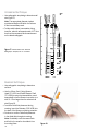
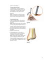
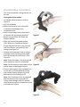
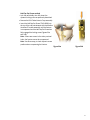
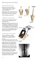
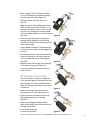
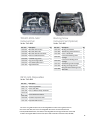
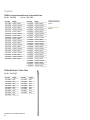
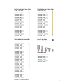
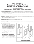
1
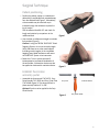
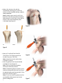
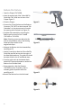
Surgical Technique Table of contents Introduction............................................................................. 3 TRIGEN™ META-NAIL™ Tibial Nail Specifications....................... 4 Surgical Technique.................................................................. 5 Patient positioning......................................................................... 5 Establish the incision and entry portal........................................... 5 Alternative technique: Entry portal..................................................7 Reduce the fracture........................................................................ 8 Determine the implant length........................................................ 9 Unreamed technique.................................................................... 10 Reamed technique........................................................................ 10 Nail assembly.................................................................................11 Nail insertion................................................................................. 12 Check nail depth........................................................................... 13 Lock the Screw.............................................................................. 14 Proximal locking............................................................................ 15 Proximal locking: Compression.................................................... 16 Blocking screw technique....................................................... 18 Incision and entry point................................................................. 18 Establish the entry portal.............................................................. 18 AP blocking screw insertion.......................................................... 18 ML blocking screw insertion......................................................... 19 Blocking screw insertion with a reducer...................................... 20 Final view: AP and ML blocking screw insertion.......................... 20 Stability blocking screw insertion................................................. 20 Final view: Stability blocking screws............................................. 21 TRIGEN nail cap insertion: optional....................................................................21 Nail extraction: optional............................................................... 22 An alternative method for extraction .......................................... 23 Catalog information............................................................... 24 Nota Bene The technique description herein is made available to the healthcare professional to illustrate the authors’ suggested treatment for the uncomplicated procedure. In the final analysis, the preferred treatment is that which addresses the needs of the patient. Introduction The following technique is for informational and educational purposes only. It is not intended to serve as medical advice. It is the responsibility of treating physicians to determine and utilize the appropriate products and techniques, according to their own clinical judgement, for each of their patients. For more information on the TRIGEN™ META-NAIL™ Tibial Nail System, ncluding its Indications for Use (REF 81068703), contraindications, and product safety information, please refer to the product’s label, the Instructions for Use packaged with the product, and, if using the TRIGEN SURESHOT™ Distal Targeting System, the TRIGEN SURESHOT Distal Targeting System User Manual (REF 7118-1540). The TRIGEN META-NAIL Tibial Nail System is designed specifically to repair fractures of the proximal and distal thirds of the tibia, including the shaft, stable and unstable fractures, nonunions, malunions, and for the prophylactic nailing of impending pathological fractures. The META-NAIL System can be used with or without the SURESHOT Distal Targeting System. If using the SURESHOT Distal Targeting System, be sure to read and understand the TRIGEN SURESHOT Distal Targeting System User Manual (REF 7118-1540). Only trained operators are allowed to use the TRIGEN SURESHOT Distal Targeting System. 3 TRIGEN™ META-NAIL™ Tibial Nail Specifications 10º 27mm Distal end of nail (all knee and distal tibial) Specifications TRIGEN META-NAIL Tibia (8.5mm) TRIGEN META-NAIL Tibia (10, 11.5 and 13mm) Material Ti6Al4V Ti6Al4V Diameter 8.5mm 10, 11.5 and 13mm Lengths 16-50cm* 16-50cm* Nail Color Grey Gold Cross Section Round Round Proximal Diameter (driving end) 12mm 12mm (10, 11.5 diameter) 13mm (13 diameter) Distal Diameter (non-driving end) 8.5mm 10, 11.5 and 13mm Smallest Thru Diameter 4.8mm 5.0mm Wall Thickness 1.9mm 2.3mm (10) 3.0mm (11.5) 2.3mm (13) Guide Bolt Thread 5/16-24 UNF 5/16-24 UNF Screw Diameter 4.5mm 5.0mm Screw Color Grey Gold Major Diameter 4.5mm 5.0mm Minor Diameter (core) 4.0mm 4.3mm Screw Lengths 25-65mm 25-110mm Hex Size 4.7mm 4.7mm Alternative Hexdrivers RT Femoral & Recon 7.0mm Cannulated Screw PERI-LOC™ Locking Screw RT Femoral & Recon 7.0mm Cannulated Screw PERI-LOC 4.7mm Hexdriver, PROFIX™ 4.7mm Hexdriver Alternative Modes No No Top view of nail Proximal Locking (Driving End) Static Lock Locations/Orientations 17mm/45° Screw Locked w/META-NAIL Cap 23mm/45° Threaded w/bushing 30mm/25° Threaded 40mm/25° Threaded 60mm 2º ML view Figure 1 Non-driving end of nail (AP view) Static Locking Hole Dimensions Threaded 4.3mm minor diameter Threaded 4.7mm major diameter Threaded 4.5mm minor diameter Threaded 5.3mm major diameter Compression/Dynamic Slot Location 10mm 10mm Compression/Dynamic Slot Diameter/Length 4.7mm/7mm 5.3mm/7mm Degree of Proximal Bend 10° (Herzog) 10° Proximal Bend Location 27mm 27mm Distal Locking (Non-Driving End) Static Lock Locations/ Orientations 25mm/ML 15mm/AP 5mm/ML (Threaded) 25mm/ML 15mm/AP 5mm/ML (Threaded) Static Locking Hole Dimensions 4.7mm** 5.3mm** Degree of Distal Bend 2° 2° Distal Bend Location 60mm 60mm Note: These views are not to scale and should * Set does not include all sizes. **Most distal hole threaded. be used as a pictorial representation only. 4 Surgical Technique Patient positioning 1. Position the patient supine on a radiolucent table with the unaffected limb extended away from the affected limb (Figure 1). Alternatively, a fracture table may be used with a pin inserted through the calcaneus to place the leg in traction. Flex the affected limb 80–90° and check for length and rotation by comparison to the unaffected limb. Figure 1 2. Use a bolster or radiolucent triangle to maintain limb position (Figure 2). Caution If using the TRIGEN™ SURESHOT™ Distal Targeting System, do not use a metal triangle. Verify that there are no other metal objects (including metal triangles) in the immediate targeting area. Metal interference will cause the SURESHOT System to be inaccurate. 3. Rotate the C-Arm to ensure optimal AP (anteroposterior) and lateral visualization of the entire tibia. A distraction device may also be applied to obtain and/or maintain traction. Figure 2 Establish the incision and entry portal 1. Assemble the Honeycomb (7167-4075), Entry Portal Handle (7167-4092) and Entry Portal Tube (7167-4060) (Figure 3). The pieces will lock in place securely at either 0° or 180°. Entry Tube Guide Pin Sleeve Optional: Suction can be applied to the Entry Portal Handle. Figure 3 Entry Portal Handle 5 2. Make a 2cm incision in line with the intramedullary canal (Figure 4). Orient the incision so that it is patellar-splitting, medial or lateral parapatellar. Note: Locate the entry point for the 3.2mm Brad Point Guide Pin just medial to the lateral tibial eminence in the AP view, in line with the anterior cortex and intramedullary canal in the lateral view (Figure 5). Figure 4 AP Lateral Figure 5 3. Attach a 3.2mm Brad Point Guide Pin (7167-4130 or 7163-1436) to the drill via the Mini Connector (7163-1186). Figure 6 Note: A wire driver can be used in place of the Mini Connector. 4. Insert the guide pin into the proximal tibia to a depth of 4–6cm (Figure 6). Note: The Entry Portal instrumentation serves as a soft-tissue protector. Note: If suboptimal guide pin insertion occurs, rotate the Honeycomb within the Entry Tube to the desired location and insert another 3.2mm Brad Point Guide Pin (Figure 7). Note: Do not over-insert the guide pin as this can establish a false trajectory and cause fracture malalignment. 6 Figure 7 5. After the guide pin is in place, remove the Honeycomb from the Entry Tube, along with any other guide pins. 6. Check the guide pin position via radiographic imaging. 7. Advance the 12.5mm Entry Reamer (7163-1116) over the guide pin through the Entry Tube to a depth of 4–6cm (Figure 8). Note: Avoid penetration of the posterior cortex. 8. Remove the Entry Reamer and guide pin. Alternative technique: Entry portal 9. Attach the T-handle (7167-4076 or 7167-4576) to Figure 8 the Cannulated Awl (7167-4000) (Figure 9). 10.Insert the awl into the proximal tibia to a depth of 4–6cm. Note: The Cannulated Awl is 9.5mm in diameter. Additional reaming is required for nail entry. 11. Insert the 3.2mm T-handle Trocar (7167-4074) (Figure 10) into the rear of the assembly prior to insertion in order to prevent awl slippage and accumulation of cortical bone within the cannulation. Cannulated Awl with T-handle Figure 9 3.2mm T-handle Trocar Figure 10 7 Reduce the fracture 1. Open the Gripper (7167-4080). 2. Insert the smooth end of the 3.0mm Ball Tip Guide Rod (7163-1626) into the front of the Gripper (Figure 11). 3. Close the Gripper. Figure 11 Gripper 4. Connect the 8.5mm Reducer and the Reducer Connector (7167-4077) so that the words “Slot Orientation” on the connector are in line with the opening at the Reducer’s tip (Figure 12). 5. Complete the assembly by connecting the Reducer and connector to the T-handle (7167-4076 or 7167-4576). Note: If blocking screws are desired at this point in the procedure, refer to the blocking screw technique section of this surgical technique. Reducer Reducer Connector Figure 12 6. Advance the Reducer into the intramedullary canal (Figure 13). 7. Use the curved tip to direct the 3.0mm Ball Tip Guide Rod past the fracture into the region of the distal epiphyseal scar. The guide rod should be center-center in the AP and lateral views. 8. Once the guide rod is at the desired depth, detach the Gripper and prepare to remove the Reducer from the tibial canal. 9. During extraction, slide the Obturator (7167-4078) into the T-handle in order to maintain guide rod position within the canal (Figure 14). Figure 13 10.Remove the Reducer from the tibial canal. Figure 14 8 Determine the implant length 1. Confirm that the Ruler opens easily. If it does not, adjust the thumb-wheel connection at the end to ensure free movement. 2. After the Reducer has been removed, reconfirm the guide rod placement within the distal tibia. 3. Slide the Ruler (7167-4079) over the guide rod until the metal tip contacts the proximal tibia (Figure 15). 4. Confirm the guide rod position in the window at the opposite end of the Ruler as shown in order to ensure accurate implant measurement (Figure 16). Figure 15 5. Push down on the top of the Ruler until it contacts the 3.0mm Ball Tip Guide Rod. Note: Ensure that the ruler is in contact with the Ball Tip Guide Rod. Window 6. Read the implant length from the exposed calibrations at the end of the Ruler. 7. Confirm fracture reduction to ensure that Thumb wheel the implant length is not underestimated. Reference the fibula for accurate fracture distraction or compression. Figure 16 9 Unreamed technique 1. Use radiographic templating to determine nail size (Figure 17). Note: The appropriate-diameter implant provides translational fill within the isthmus of the intramedullary canal. 2. To help avoid implant incarceration during insertion, select a nail approximately 1.0–1.5mm less than the narrowest canal measurement on the lateral radiograph. Figure 17: TRIGEN™ META-NAIL™ Tibial Nail Radiographic Template, Cat. No. 7118-0810 Reamed technique 1. Use radiographic templating to determine nail size. 2. Use the 9.0mm Front Cutting Reamer Head (7111-8231) and Flexible Reamer Shaft (7111-8200) to ream the intramedullary canal sequentially in half-millimeter increments to a size 1.0–1.5mm larger than the selected nail size (Figure 18). 3. To ensure Guide Rod placement during reaming, insert the Obturator (7167-4078) into the back of the Reamer unit during retraction. 4. Continue to confirm Guide Rod placement in the distal tibia throughout reaming. Note: Periodically move the reamer back and forth in the canal to clear debris from the cutting flutes. 10 Figure 18 Nail assembly 1. Use the Guide Bolt (7165-4506) to attach the META-NAIL™ Drill Guide (7165-4502) to the nail. Guide Bolt 2. Tighten with the Guide Bolt Wrench (7163-1140) and T-handle. The nail is correctly aligned when: META-NAIL Drill Guide }} The vertical black line on the posterior side of the insertion barrel aligns with the line on the posterior side of the nail. }} The “A” on the anterior side of the nail aligns with the “A” on the anterior side of the insertion barrel (Figure 19). TRIGEN™ META-NAIL Figure 19 }} The apex of the nail’s proximal Herzog Bend faces posteriorly and the Drill Guide is oriented anteriorly (Figure 20). Note: The bevel on the front of the nail marks the connection to the Drill Guide and can be seen in the lateral view as a means to determine proximal insertion depth. Note: The standard META-NAIL Drill Guide and Guide Bolt are recommended for use for compression or dynamic locking. When compared to using the META-NAIL Extension Drill Guide, the longer insertion barrel of the standard META-NAIL Drill Guide facilitates countersinking of the nail. Note: The assembly and insertion of the grey 8.5mm diameter META-NAIL Tibial Nail follows the same technique as the 10mm, 11.5mm and 13mm diameter nails. Figure 20 3. Attach the Cannulated Impactor-Medium (7167-5081) to the Drill Guide (Figure 21). 4. Attach the Anterior Drop (7165-4501) to the Drill META-NAIL Anterior Drop Guide (Figure 21). 5. To verify the accuracy of the target, insert a gold 9.0mm Drill Sleeve (7163-1152) and silver 4.0mm Drill Sleeve (7167-4083) into the Drop. 6. Pass a 4.0mm Long Pilot Drill (7163-1110)* through the assembly. 9.0mm Drill Sleeve Note: An incorrectly attached nail will not target. Figure 21 *The 4.0mm Long Pilot Drill (7163-1110) is interchangeable with the 4.0mm AO Long Drill (7163-1121) 11 Nail insertion 1. Detach and remove the Anterior Drop. 2. Attach the Cannulated Impactor-Medium (7167-5081) to the Drill Guide (Figure 22). 3. Orient the Drill Guide assembly in the AP (anteroposterior) position. 4. Use the Slotted Hammer (7167-4082) to tap and advance the nail over the guide rod to the desired depth (Figure 22). Note: if excessive force is required to insert the nail, additional reaming of the intramedullary canal may be required. 5. Verify fracture reduction as the nail crosses the fracture site, paying close attention to rotation, length, alignment, distraction and/or shortening. 6. Check the final nail position in both the AP Figure 22 and lateral views for correct alignment. Note: To obtain provisional fixation of the proximal tibial fragments, reattach the Anterior Drop and insert the gold 9.0mm Drill Sleeve (7163-1152) and silver 4.0mm Drill Sleeve (7167-4083) into one of the two Blocking Screw holes in the Drop, then pass a 4.0mm Long Pilot Drill (7163-1110) through the drill sleeves. Note: For proximal interlocking with the leg in extension, use the Extension Drill Guide (7165-4503) and Extension Guide Bolt (7165-4505). The long insertion barrel of the standard Drill Guide may impinge upon the distal femoral condyles and prevent the nail from interlocking with the tibia in full extension (Figure 23). Note: The TRIGEN™ SURESHOT™ Distal Targeting System cannot be used with the META-NAIL™ Extension Drill Guide. 12 Figure 23 Check nail depth Check proximal nail depth In the lateral view, confirm nail position by observing the nail/Drill Guide junction. Each circular groove on the Drill Guide’s insertion barrel represents a 10mm depth interval (Figure 24). Note: If compression or dynamic locking is desired, countersink the nail approximately 10mm in order to avoid implant prominence. Check distal nail depth 1. In the AP and lateral views, confirm that the nail has been inserted to the desired depth (Figure 25). Figure 24 Note: Optimal insertion depth, which will allow room for screw insertion below the fracture, is essential. Distal third tibial fractures require at least three locking screws to maintain stability. 2. Remove the Guide Rod once the nail has been fully seated. 3. Reattach the Anterior Drop. 4. Following nail insertion, confirm that the nail and Drill Guide are securely connected. Hammering can loosen the Guide Bolt. Note: For information regarding drilling distal holes and distal screw insertion using the TRIGEN™ SURESHOT™ Targeting System, refer to the TRIGEN SURESHOT Targeting System User Manual (7118-1540). Figure 25 13 Lock the Screw Determine the Locking Screw length A There are three options available to determine the locking screw lengths: }} The Gold 9.0mm Drill Sleeve, silver 4.0mm Drill Sleeve and 4.0mm Long Pilot Drill* (Figure 26-A) }} The Screw Depth Gauge (7163-1189) (Figure 26-B) }} The Screw Length Sleeve (7167-4085) and 4.0mm Short Drill (7163-1117)** (Figure 26-C) Note: For information regarding Drill Depth Measurement Software (DDM) using the TRIGEN™ SURESHOT™ Targeting System, refer to the TRIGEN SURESHOT Targeting System User Manual (7118-1540). The DDM software can be used for distal locking only. B C Figure 26 Insert the Locking Screws Proximal locking options include three statically locked threaded holes and one slot that allows for both fracture compression and/or dynamization (Figure 27). These are targeted through the orange and blue color-coded holes on the Anterior Drop. Distal locking options include three statically locked holes: two ML (mediolateral) holes and one AP hole. The most distal ML hole is threaded for additional stability. Gold 5.0mm locking screws are compatible with 10mm, 11.5mm and 13mm diameter nails. Grey 4.5mm locking screws are compatible with 8.5mm diameter nails. Note: Do not use the 4.0mm Short Step Drill (7164-1123) when drilling for a grey 4.5mm locking screw. Its diameter transitions from 4.0mm to 4.7mm and will drill too large a hole in the near cortex, which may compromise locking Figure 27: screw purchase. META-NAIL™ Tibial Nail with all four proximal screws inserted *The 4.0mm Long Pilot Drill (7163-1110) is interchangeable with 4.0mm AO Long Drill (7163-1121) **The 4.0mm Short Drill (7163-1117) is interchangeable with 4.0mm AO Short Drill (7163-1123) 14 Proximal locking Static locking 1. Make a small incision at the site of screw entry. 2. Insert the gold 9.0mm Drill Sleeve and silver 4.0mm Drill Sleeve through the static slot on the Anterior Drop (Figure 28) down to bone. 3. Drill both cortices with the 4.0mm Long Pilot Drill*. 4. Measure for screw length using either the Figure 28 calibrations on the 4.0mm Long Pilot Drill* or by removing the 4.0mm Drill Sleeve and using the Screw Depth Gauge. 5. Attach the appropriate length screw to the end of the Medium Hexdriver (7163-1066). 6. Use power to insert the screw through the gold 9.0mm Drill Sleeve until the laser-etched ring on the Hexdriver reaches the back of the Drill Sleeve. 7. Attach the T-handle to the Hexdriver. 8. Tighten the screw by hand. Dynamic locking 9. With the nail countersunk approximately 10mm, make a small incision at the site of screw entry and insert the gold 9.0mm Drill Sleeve and silver 4.0mm Drill Sleeve through the dynamic slot on the Anterior Drop down to bone (Figures 29 and 30). Figure 29 10.Drill both cortices with the 4.0mm Long Pilot Drill*. 11. Use the techniques described in the “Lock the Screw” section to measure and insert the screw. Note: If the screw is left in the dynamic mode, a nail cap cannot be used as it will push against the locking screw. Figure 30 *The 4.0mm Long Pilot Drill (7163-1110) is interchangeable with 4.0mm AO Long Drill (7163-1121) 15 Proximal locking: Compression One of two compression locking methods can be used: Compression Driver method 1. Countersink the nail a minimum of 10 mm (Figure 31). 2. Lock the nail distally. 3. Reduce the fracture as much as possible to maximize the advantage of the compression driver. 4. Insert a screw through the proximal side of the dynamic slot as previously described. Figure 31 5. Remove the gold 9.0mm Drill Sleeve and Medium Hexdriver. 6. Attach the Universal Compression Driver (7165-4528) to the T-handle and thread it through the guide bolt into the top of the nail until it contacts the most proximal 5.0mm locking screw (Figure 32). 7. Advance the Compression Driver by turning it clockwise to drive the locking screw distally, which will compress the fracture up to 7mm (Figure 32). Note: If there are screws in the other proximal holes, the fracture cannot be compressed. Note: Use flouroscopy to check dynamic screw position when compressing the fracture. Figure 32 8. Once the fracture gap is fully compressed, lock the nail with up to three additional proximal static screws while the Anterior Drop is still attached to the Drill Guide (Figure 33). Note: If the Compression Driver is progressed after the fracture is fully compressed, the locking screw will begin to bend. In extreme cases where excess force is applied, the screw may break upon removal. Figure 33 16 Nail Cap Set Screw method 1. Lock the nail distally, then fully insert the dynamic locking screw as previously described. 2. Remove the Drill Guide/Anterior Drop assembly. 3. Insert the Nail Cap Set Screw (7165-6000) into the top of the nail and advance with the Medium Hexdriver/T-handle assembly until the fracture is compressed and the Nail Cap Set Screw has fully engaged the locking screw (Figures 34a and 34b). Note: If there are screws in the other proximal holes, the fracture cannot be compressed. Note: Use flouroscopy to check dynamic screw position when compressing the fracture. Figure 34a Figure 34b 17 Blocking screw technique Incision and entry point Make a 2cm incision in line with the intramedullary canal. Orient the incision so that it is patellar splitting, medial or lateral parapatellar. Note: Locate the entry point just medial to the lateral tibial eminence in the AP view, in line with the anterior cortex and intramedullary canal in the lateral view (Figure 35) Establish the entry portal AP Figure 35 Insert the 11.0mm T-handle Awl (7165-4522) manually to a depth just proximal to the fracture (Figure 36). Note: When creating the initial entry point, pay close attention to the trajectory of the awl and the relationship to the anatomic axis of the tibia. Correct awl trajectory in the proximal fragment must be established prior to alignment with the Metal handle anatomic axis of the distal fragment (Figure 36). This will ensure accurate fracture reduction when the nail is inserted. AP blocking screw insertion In order to prevent varus or valgus malalignment of the proximal fragment, blocking screws may be placed in the AP plane. 1. Attach the Blocking Screw Device (7165-4515) to the 11.0mm T-handle Awl and move it into the desired position in the AP plane (Figure 37). Cartridge Figure 37 Note: The Blocking Screw Alignment Pins (7165-4523) can be screwed into the three threaded holes on the metal handle of the Blocking Screw Device to serve as external points of reference during fracture alignment. 2. Tighten the device to the awl and insert the appropriate Blocking Screw Cartridge (7165-4511, 7165-4513, or 7165-4514). 3. Adjust the cartridge proximally or distally within the Blocking Screw Device to determine the blocking screw position (Figure 38). 18 Lateral Figure 38 Figure 36 T-handle awl 4. Insert the gold 9.0mm Drill Sleeve and silver 4.0 mm Drill Sleeve into the desired cartridge hole and down to the bone (Figure 39). 5. Drill both cortices with the 4.0mm Long Pilot Drill*. Note: Use caution during drilling and insertion of the blocking screws in the AP plane. Do not drill past the posterior cortex or insert a screw that is too long. Damage to the neurovascular structures located posterior to the proximal tibia Figure 39 may result. 6. Determine the screw length by reading the exposed drill bit calibrations or by removing the 4.0mm Drill Sleeve and measuring with the Screw Depth Gauge. 7. Use the Medium Hexdriver/T-handle assembly to insert the screw until the screw engages the far cortex. 8. Following implantation of the proximal blocking screw and reduction of the fracture, pass the 11.0mm T-handle Awl into the distal fragment (Figure 40). Figure 40 9. Reposition either the Blocking Screw Cartridge or the awl as necessary and follow the previously described technique for blocking screw insertion. ML blocking screw insertion To prevent anterior or posterior malalignment of the proximal fragment, blocking screws may also be placed in the ML (mediolateral) plane. 1. Attach the Blocking Screw Device to the 11.0mm T-handle Awl. Figure 41 2. Rotate the blocking screw device into the desired position in the ML plane (Figure 41). 3. Tighten the device to the awl and insert the appropriate Blocking Screw Cartridge (Figure 42). 4. Adjust the cartridge proximally or distally within the Blocking Screw Device to determine blocking screw position. 5. Insert the blocking screw as previously described. Figure 42 *The 4.0mm Long Pilot Drill (7163-1110) is interchangeable with 4.0mm AO Long Drill (7163-1121) 19 Blocking screw insertion with a reducer Blocking screws can also be inserted by attaching the Blocking Screw Device to the Reducer instead of the 11.0mm T-handle Awl (Figure 43). Follow the previously described blocking screw insertion technique. Final view: AP and ML blocking screw insertion 1. Once blocking screw insertion is complete, remove the Blocking Screw Device from the 11.0mm T-handle Awl or Reducer. 2. Obtain both AP and lateral radiographic images to confirm accurate placement. Figure 43 Note: The Awl or Reducer provides a reliable indication of the nail’s insertion trajectory based upon the location of the blocking screws. Figure 44 3. Confirm proper screw placement (Figure 44). 4. Proceed with tibial nail insertion. Stability blocking screw insertion Following nail insertion and confirmation of fracture reduction, blocking screws can be placed on either side of the nail in the metaphyseal region for additional stability. Screws may be inserted in both the AP and ML planes. 5. With the nail inserted, attach the Tibial Blocking Screw Attachment (7165-4509) (Figure 45) to the Anterior Drop (triangle to triangle for AP screws and square to square for ML screws). Figure 45 6. Follow the previously described techniques for cartridge positioning and blocking screw insertion (Figure 46). Note: The AP blocking screws targeted through the two holes built into the Anterior Drop cannot be used if the most inferior oblique proximal locking screw has been inserted. The blocking screws are located 53mm below the proximal tip of the nail. Figure 46 20 Final view: Stability blocking screws 1. Once stability blocking screw insertion is complete, remove the Blocking Screw Attachment and Anterior Drop from the Drill Guide. 2. Obtain both AP and lateral radiographic images to confirm accurate screw placement (Figures 47 and 48). TRIGEN™ Nail Cap insertion: optional 1. Figure 47 Figure 48 Remove the Drill Guide/Anterior Drop assembly. 2. Attach the selected Nail Cap (Figure 49) to the Medium Hexdriver/T-handle assembly. 3. Insert the Nail Cap into the top of the nail until it is tight. Caution: A Nail Cap cannot be used if a Nail Cap Set Screw is implanted or if a locking screw is inserted in the dynamic locking position. The tip of the Nail Cap will contact the locking screw and prevent complete engagement of the Nail Cap with the nail. Figure 49 Note: If cross-threading occurs, rotate the Nail Cap counterclockwise until its threads line up with those of the nail. Proceed with the Nail Cap insertion until it is tight. Accurate screw placement (Figures 47 and 48). 21 Nail extraction: optional Standard technique 1. Use the Medium Hexdriver/T-handle assembly to remove the Nail Cap or Nail Cap Set Screw, if implanted, all of the distal locking screws, and all but one of the proximal locking screws. (Figure 50). 2. Thread the Cannulated Impactor-Medium (7167- 5081) or Cannulated Impactor-Long (7163-1185)* into the back of the Disposable Nail Extractor (7163-1320)**. 3. Thread the assembly into the top of the nail. 4. Remove the remaining proximal locking screw. 5. Use the Slotted Hammer with a back-slapping motion to extract the nail (Figure 50). Figure 50 Percutaneous technique In the absence of a Nail Cap or Nail Cap Set Screw: 6. Use the Medium Hexdriver/T-handle assembly to remove all distal locking screws and all but one of the proximal locking screws. 7. Under fluoroscopy, insert a 3.2mm Brad Point Figure 51 Tip Guide Pin (7167-4130 or 7163-1436) into the top of the nail either using power or by hand (Figure 51). 8. Make a 2cm incision around the pin. 9. Advance the 12.5mm Entry Reamer over the pin and into the top of the nail to remove any bony ingrowth (Figure 52). 10.Thread the Cannulated Impactor-Medium or Cannulated Impactor-Long* (7163-1185) into the back of the Disposable Nail Extractor** (7163-1320). 11. Thread the assembly into the top of the nail. Note: It is the flared portion of the Entry Reamer that enters the top of the nail. 12.Remove the remaining proximal locking screw. 13.Extract the nail with a back-slapping motion. Figure 52 *The Cannulated Impactor-Long is located in the original TRIGEN™ Instrument Set (7163-1326) **The Disposable Nail Extractor (7163-1320) is interchangeable with the Large Nail Extractor located in the original TRIGEN™ Instrument Set (7163-1326) and the HFN™ Instrument Set (7170-0001) 22 An alternative method for extraction 1. Guide rod jamming technique Guide rods Advance the end of a 3.0mm Ball Tip Guide Rod through the end of the nail. Cat. No. Description 7163-1626 3.0mm x 1000mm Ball Tip Guide Rod 7175-1146 2.0mm x 600mm Ball Tip Guide Rod 2. Insert the smooth end of a 2.0mm Ball Tip Guide Rod (7175-1146) in the same manner. 3. With both guide rods in place, attach the Gripper to the end of the 3.0mm Ball Tip Guide Rod. 4. Pull the Gripper back so that it wedges the ball Additional removal items Cat. No. Description 115074 Large Extractor Hook* 115073 Small Extractor Hook* tip against the 2.0mm Guide Rod. 5. Backslap against the Gripper with the Slotted Hammer to extract the nail. *Available sterile packed. For nail removal only: do not use for nail insertion. 23 Catalog information TRIGEN™ Base Instrument Set Set No. 7167-4012 Cat. Item Description Qty Cat. Item Description Qty 7112-9401 Small Outer Case 1 7167-4078 Obturator 1 7112-9402 Lid for Outer Case 1 7167-4079 Ruler 1 Gripper 1 7167-4021 TRIGEN Base Tray 1 7167-4080 7163-1066 Medium Hexdriver 1 7167-4081 Impactor 1 Slotted Hammer 1 7163-1068 Short Hexdriver 1 7167-4082 7163-1116 12.5mm Entry Reamer 1 7167-4083 4.0mm Drill Sleeve 2 Screwdriver Release Handle 1 7163-1140 Guide Bolt Wrench 1 7167-4084 7163-1152 9.0mm Drill Sleeve 2 7167-4085 Screw Length Sleeve 1 Entry Portal Handle 1 7163-1161 Multipurpose Driver 1 7167-4092 7163-1186 Mini Connector 1 7167-1212 TRIGEN Reamer Set, Optional 1 7163-1189 Screw Depth Gauge 1 7111-8200 1 7167-4000 Cannulated Awl 1 SCULPTOR™ Flexible Reamer, Optional 7167-4060 Entry Portal Tube 1 7163-1130 Flexible Reamer Extender, Optional 1 7167-4074 3.2mm T-handle Trocar 1 7164-1123 TRIGEN 4.0 Diaphyseal Drill 1 7167-4075 Honeycomb 1 7163-1121 2 7167-4076 or 7167-4576 4.0mm Long AO Pilot Drill, 333mm, Disposable T-handle 1 7167-1123 4.0mm Short AO Pilot Drill, 161mm, Disposable 1 7167-4077 Reducer 1 7167-4130 3 7167-4077 Reducer Connector 1 3.2mm x 343mm Brad Point Tip Guide Pin, Disposable 7163-1070 Long Hexdriver, Optional 1 7175-1153 AO Mini Connector, Optional 1 7163-1187 Trinkle to Mini Connector, Optional 1 24 TRIGEN™ META-NAIL™ Instrument Set Blocking Screw Instrument Set (Optional) Set No. 7165-4001 Set No. 7165-4002 Cat. Item Description Qty Cat. Item Description Qty 7165-4501 META-NAIL Anterior Drop 1 7165-4515 Blocking Screw Device 1 7165-4502 META-NAIL Drill Guide 1 7165-4509 Tibial Blocking Screw Attachment 1 7165-4503 META-NAIL Extension Drill Guide 1 7165-4522 11.0mm T-handle Awl 1 7165-4505 Extension Guide Bolt (23mm) 2 7165-4506 Guide Bolt Long (51mm) 2 7165-4511 8.5mm/10mm Blocking Screw Cartridge 1 7165-4520 Long Screw Length Sleeve 1 7165-4513 1 7165-4554 Cannulated Impactor-Short 1 11.5mm/13mm Blocking Screw Cartridge 7163-1025 Large Nail Extractor 1 7165-4514 Offset Blocking Screw Cartridge 1 7165-4523 Blocking Screw Alignment Pin 2 7163-4508 Retrograde Femoral Blocking Screw Attachment 1 META-NAIL Disposables Set No. 7165-4003 Cat. Item Description 7163-1110 4.0mm Long Pilot Drill* 7163-1117 4.0mm Short Drill** 7163-1626 3.0mm x 1000mm Ball Tip Guide Rod 7167-4130 or 7163-1436 3.2mm Brad Point Guide Pin 7165-4528 Universal Compression Driver 7163-1320 Disposable Nail Extractor*** *The 4.0mm Long Pilot Drill (7163-1110) is interchangeable with 4.0mm AO Long Drill (7163-1121) **The 4.0mm Short Drill (7163-1117) is interchangeable with 4.0mm AO Short Drill (7163-1123) ***The Disposable Nail Extractor (7163-1320) is interchangeable with the Large Nail Extractor (7163-1278) located in the original TRIGEN Instrument Set (7163-1326) and the HFN™ Instrument Set (7170-0001) 25 Implants TRIGEN™ Internal Captured Screws 4.5mm and 5.0mm Set No. 71642005 Set No. 7164-2000 Cat. Item 7164-5420 7164-5422 7164-2125 7164-2127 7164-2130 7164-5432 7164-2135 7164-5437 7164-2140 7164-5442 7164-2145 7164-5447 7164-2150 7164-5452 7164-5455 7164-5457 7164-5460 7164-5462 7164-5465 Length 4.5mm x 20mm 4.5mm x 22.5mm 4.5mm x 25mm 4.5mm x 27.5mm 4.5mm x 30mm 4.5mm x 32.5mm 4.5mm x 35mm 4.5mm x 37.5mm 4.5mm x 40mm 4.5mm x 42.5mm 4.5mm x 45mm 4.5mm x 47.5mm 4.5mm x 50mm 4.5mm x 52.5mm 4.5mm x 55mm 4.5mm x 57.5mm 4.5mm x 60mm 4.5mm x 62.5mm 4.5mm x 65mm Cat. Item 7164-5020 7164-5022 7164-5025 7164-5027 7164-5030 7164-5032 7164-5035 7164-5037 7164-5040 7164-5042 7164-5045 7164-5047 7164-5050 7164-5052 7164-5055 7164-5057 7164-5060 7164-5062 7164-5065 7164-5067 7164-5070 7164-5072 7164-5075 TRIGEN META-NAIL™ 8.5mm Tibial Set No. 7165-3002 Cat. Item 7165-5024* 7165-5026* 7165-5028* 7165-5029 7165-5030* 7165-5031 7165-5032* 7165-5033* 7165-5034* Length 24cm 26cm 28cm 29cm 30cm 31cm 32cm 33cm 34cm Cat. Item 7165-5035* 7165-5036* 7165-5037* 7165-5038* 7165-5039 7165-5040 7165-5041 7165-5042 *Contained in the standard implant set 26 Length 35cm 36cm 37cm 38cm 39cm 40cm 41cm 42cm Length 5.0mm x 20mm 5.0mm x 22.5mm 5.0mm x 25mm 5.0mm x 27.5mm 5.0mm x 30mm 5.0mm x 32.5mm 5.0mm x 35mm 5.0mm x 37.5mm 5.0mm x 40mm 5.0mm x 42.5mm 5.0mm x 45mm 5.0mm x 47.5mm 5.0mm x 50mm 5.0mm x 52.5mm 5.0mm x 55mm 5.0mm x 57.5mm 5.0mm x 60mm 5.0mm x 62.5mm 5.0mm x 65mm 5.0mm x 67.5mm 5.0mm x 70mm 5.0mm x 72.5mm 5.0mm x 75mm 4.5mm 5.0mm TRIGEN™ META-NAIL™ 10mm Tibial Set No. 7165-3000 TRIGEN META-NAIL 11.5mm Tibial Set No. 7165-3001 Cat. Item 7165-5124 7165-5126 7165-5128* 7165-5129 7165-5130* 7165-5131 7165-5132* 7165-5133 7165-5134* 7165-5135* 7165-5136* 7165-5137* 7165-5138* 7165-5139* 7165-5140* 7165-5141 7165-5142 Cat. Item 7165-5224 7165-5226 7165-5228 7165-5229 7165-5230* 7165-5231 7165-5232* 7165-5233 7165-5234* 7165-5235* 7165-5236* 7165-5237* 7165-5238* 7165-5239* 7165-5240* 7165-5241 7165-5242 Length 24cm 26cm 28cm 29cm 30cm 31cm 32cm 33cm 34cm 35cm 36cm 37cm 38cm 39cm 40cm 41cm 42cm TRIGEN META-NAIL 13mm Tibial Cat. Item 7165-5318 7165-5320 7165-5322 7165-5324 7165-5326 7165-5328 7165-5329 7165-5330 7165-5331 7165-5332 Length 18cm 20cm 22cm 24cm 26cm 28cm 29cm 30cm 31cm 32cm 7165-5333 33cm 7165-5334 7165-5335 7165-5336 7165-5337 7165-5338 7165-5339 7165-5340 7165-5341 7165-5342 7165-5343 7165-5344 7165-5346 7165-5348 7165-5350 34cm 35cm 36cm 37cm 38cm 39cm 40cm 41cm 42cm 43cm 44cm 46cm 48cm 50cm Length 24cm 26cm 28cm 29cm 30cm 31cm 32cm 33cm 34cm 35cm 36cm 37cm 38cm 39cm 40cm 41cm 42cm Nail Cap Set Screw Cat. Item 7165-6000 TRIGEN Nail Caps Cat. Item 7163-4000 7163-4005 7163-4010 7163-4015 7163-4020 Length 0mm 5mm 10mm 15mm 20mm *Contained in the standard implant set 27 Caution: U.S. Federal law restricts these devices to sale by or on the order of a physician. Smith & Nephew, Inc. 1450 Brooks Road Memphis, TN 38116 USA www.smith-nephew.com Telephone: 1-901-396-2121 Information: 1-800-821-5700 Orders/Inquiries: 1-800-238-7538 ™Trademark of Smith & Nephew. Certain marks Reg. US Pat. & TM Off. 28 ©2015 Smith & Nephew. 01359 V3 71181610 REVC 04/15