1
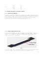
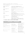
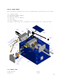
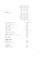
STRYCO PRODUCTS COMPANY
MANUFACTURERS OF PRECISION
WELDING MACHINES
MODEL MF40 BAND SAW WELDER
SERVICE MANUAL
STRYCO OPERATING MANUAL
INTRODUCTION
Stryco’s MF series band saw welders use the flash-butt welding
process. In this process, the ends are butted together or a small gap
is allowed between the ends - enough to permit an arc to form across
the material. When the operating switch is closed, current begins to
flow, and is changed in the transformer from high voltage, low
amperage to low voltage, high amperage. As current begins to flow
through the secondary of the transformer and through the blade the
circuit is complete.
The small gap between the ends of the blade causes the current to jump
or arc across the ends of the material. On the very small blades, the
current cuts off at the moment of upset. On the wider, heavier
blades, the current remains on for a short period of time while the
upset is taking place. This arcing or flashing process heats up the
ends of the blades. Arcing causes the blade material to burn away, as
it burns away the carriage is advanced by controlled spring pressure
maintaining the same gap so the arc will not quench. If the carriage
advances too rapidly, the gap will be closed and arcing will cease.
If the carriage advances too slowly, the gap will be too wide for the
arc to jump across, and the arcing will stop.
After reading the operating manual, should you still have trouble
welding and annealing a particular blade, contact STRYCO. We can
arrange for you to send samples of your blade stock to us for welding
(at no charge) and give you the specific recommended settings
required.
TABLE OF CONTENTS
1.0
2.0
3.0
4.0
5.0
6.0
7.0
8.0
9.0
10.0
11.0
12.0
13.0
Pg
SPECIFICATIONS............................... 3
GENERAL OPERATING INSTRUCTIONS............... 4
BASIC OPERATING PARTS........................ 5
BASIC OPERATING PARTS LOCATION............... 6
TYPICAL OPERATING SEQUENCE................... 7
SPECIAL ADJUSTMENTS.......................... 9
PREVENTIVE MAINTENANCE.......................11
SUGGESTED SETTINGS...........................13
DIAGNOSTIC CHART FOR TROUBLE-SHOOTING........15
ELECTRICAL SCHEMATIC.........................17
SAFETY REMINDERS.............................18
BUYERS GUIDE.................................19
PARTS LIST...................................20
2
1.0 SPECIFICATIONS
MODEL MF40
Stock Range
Width: 1.0 in. max., .25 in. min.
Thickness: .060 in. max., .020 in. min.
Material
Steel Flat Stock/Bandsaw Blade Stock
Line Current
230 VAC 39 amps
@ 10% duty cycles
50/60 Hz *12 amps @ 100% duty cycle
460 VAC 20 amps
@ 10% duty cycle
50/60 HZ *6 amps @ 100% duty cycle
*Fusing amperage requirement.
Choose next larger size of slow blow fuse.
Single Phase Transformer
4 KVA @ 50% duty cycle
Heat Selection
Continuous
Upset Pressure Method
Spring type
Clamp Pressure
Offset Cam Type
Dimensions and Weight
Overall Height Bench/Truck:
Die Height Bench/Truck:
Floor Space Bench/Truck:
Weight Bench/Truck:
15-1/2”/45-1/2”
12-3/4”/42-3/4”
22”x17”/28”x24”
265lbs./378lbs.
Standard Features:
Designed with low maintenance and ease of operator adjustments in mind
Dual shaft headpiece with linear ball bearings
Built-in solid state SCR weld control
Options:
Choice of 575v, 460v, 415/380v, 230v, or 208v operation
Motor Grinder
Anneal timer
C E Operation
3
2.0 GENERAL OPERATING INSTRUCTIONS
2.1 ELECTRICAL HOOK-UP INSTRUCTIONS
First determine that available electrical service in your plant
corresponds to the nameplate rating located on welder housing.
Electrical wiring to welder must be of sufficient size to deliver full
ampere load with no appreciable loss during the weld cycle. The welder
will not operate properly if there is more than a 10% variation in the
line voltage. Consult the welder specifications for fusing and cable
hook-up sizing.
Refer to National Electrical Code and local electrical regulations for
adequate power sizes disconnect methods and fusing guidelines.
Remember line voltages to the welding machine are potentially
dangerous should the power cords be damaged or severed. The welding
voltages at the welding dies will not harm an operator since they do
not exceed 10 volts.
2.1.1 MACHINE HOOK-UP INSTRUCTIONS
To connect the electrical cables to the welder, first remove the right
hand access panel (see FIG. 1). Locate the access port in the rear
bottom left hand corner of the housing. Then feed the cables through
the access port and connect the power cables to L1 and L2. Next
connect the safety ground cable to the ground stud. Make sure all
connections are securely fastened and then re-attach the right hand
access panel.
2.2 SAFETY PRECAUTIONS (See section 11.0)
4
2.2.1 ELECTRICAL
Maintain electrical cable to welder in good repair. Welder must be
grounded and connections securely tightened. Heat switch must not be
changed to new position while a weld cycle is in process. DISCONNECT
ELECTRICAL SERVICE BEFORE SERVICING WELDER - high voltages are located
within the base of the welder.
2.2.2 MECHANICAL
An operator must wear safety glasses while using the welder. Keep all
safety guards on welders and use properly. Operators must be
instructed on basic operation of the unit to prevent injury. Check
the nameplate rating and keep within material size range for each
welder.
2.3 WELDING DIES
The dies and shoes supplied with the welder will handle most size and
material types within the range of the welder. For new applications
consult the factory for special die and shoe sets.
3.0 BASIC OPERATING PARTS
3.1 WELDING HEAT
Welding heat is obtained by means of a weld heat selection switch
located on the welder housing. Accompanying charts will assist in
settings for various sizes.
3.2 SPACING MECHANISM (Operating Lever)
The welder is capable of welding a variety of blade sizes. Spacing is
obtained by moving the spacing lever up to engage the first or weld
position. The spacing lever is located on right hand side of the
headpiece and determines the welding starting space. Accompanying
charts will assist in settings for various sizes.
3.3 UPSET PRESSURE
Upset pressure adjustments are determined by the size of the material
being welded. Turning the Upset Force Adjustment bolt clockwise will
increase the force, while turning it counterclockwise will decrease
the force.
3.4 WELDING DIES AND DIE SHOES
Welding dies serve three purposes: (1) to carry current for welding,
(2) to align the two ends of stock, (3) and prevent material slippage
during a weld cycle. Welding die shoes hold the stock firmly within
dies during fusion.
5
3.5 CLAMP HANDLES
The clamp handles apply force between the upper shoe and the lower die
gripping the stock securely. The larger the stock clamped, the
greater the clamp force applied to that stock.
CAUTION!! Clamping stock thicker than the recommended maximum size
may cause clamp spring failure. (See welder specifications for stock
sizes.)
4.0 BASIC OPERATING PARTS LOCATION
FIG. 2
5.0 TYPICAL OPERATING SEQUENCE
6
1. Adjust weld heat selection switch to proper setting.
2. Adjust flash speed dial. (If needed)
3. Move spacing lever up to open the welding dies to the weld
position.
4. Place stock into welding dies so the blade ends meet midway
between each welding die. Hold the blades against the guides.
Rotate the clamping levers upwards to secure the blades.
5. Press weld button located on right side of the welder.
6. Release spacing lever by pulling it down.
7. After the weld is completed unclamp the stock, leaving the weld
upset burr intact.
8. Hard drawn stock or high carbon blades require an anneal
operation.
9. Trim off the weld burr so the weld area is equal to parent
material. Incomplete burr removal or under cutting will cause
subsequent blade breaks.
5.1 PREPARING BLADES FOR WELDING
The blade to be joined must be free of rust, corrosion or other
insulating materials. Clean the blade where it contacts the welding
dies. (Refer to section 8.0 for approximate settings)
When welding saw blades, it is sometimes necessary to match the teeth.
When attempting to match the teeth, we recommend that you compensate
for the distance traveled during the weld sequence. Blade material
will burn off during the flashing upset process.
On some saw blades, the set may interfere with the electrical contact
across the full width of the blades or it may damage the welding jaws
- especially on heavier saw blades. To avoid this problem, it may be
necessary to bevel the top and bottom jaws (Fig 3). Beveling may be
accomplished by grinding the jaws shown (Fig 3,4).
FIG. 3
7
FIG. 4
5.2 TYPICAL ANNEAL OPERATION
1.
2.
3.
4.
Set the anneal timer. (Option)
Move spacing lever completely up to open the welding
jaws to the anneal position.
Re-clamp welded stock into the welding dies with the upset
burr centered midway between dies.
Press the anneal button with a jogging action to heat up
welded area to the desired temperature.
5.3 ADDITIONAL ANNEALING NOTES
1.
2.
Steel blades will start to turn a dull red at 1000 degrees F.
Steel blades will start to breakout in small dark circular
flakes at about 1375 degrees F.
3. The blade should be annealed prior to removing the weld burr.
Some value may be gained by a second anneal after weld flash or
burr is removed.
5.4 ANNEAL SETTINGS
BAND SAW
WIDTH
(INCHES)
ANNEAL
HEAT
(PERCENT)
ANNEAL
TIME
(SECONDS)
1/8 - 1/4
30
2
1/4 – 1/2
35
2
1/2 – 3/4
35
3
3/4 – 1.0
40
4
8
6.0 SPECIAL ADJUSTMENTS
FIG. 5
9
FIG.6
6.1 LIMIT SWITCH ADJUSTMENTS
WARNING! REMOVE POWER FROM THE WELDER BEFORE MAKING THESE
ADJUSTMENTS
6.1.1 Lift the operating lever into the first weld position so that
the welding dies are approximately 7/16”-9/16” apart at the
front edges.
6.1.2 Limit switch cut-off
A. With no stock in the dies, slowly lower the operating lever
down and listen for the limit switch activation.
B. The spacing between the dies at this activation point should
be 1/8 of an inch.
6.1.3 Should activation not occur at this point, adjust limit
switch adjusting screw to satisfy this condition. See FIG. 6.
Do not let the plunger stop ring bottom out against the plunger
housing. This may cause the switch to fail after repeated
cycles.
6.2 INSTALLATION AND ADJUSTMENT OF WELDER UPSET SPRING
A.
B.
C.
D.
Using the operating lever, close the welder headpiece.
Remove the upset force adjuster.
Remove the old upset spring and replace it with a new one.
Re-install the upset force adjuster.
6.3 JAW SPACING
A.
The weld open spacing is the distance the right end of the
left jaw is from the left end of the right jaw when the
operating lever is in the cocked or weld position.
10
B. To check for the weld closed spacing, pull the operating
lever down. Once closed, this spacing should be between 1/32
and 1/16 of an inch. This is a factory setting and normally
requires no adjustment. If needed, this space can be changed
by use of the closed space adjuster. See FIG. 5.
6.4 FLASHING SPEED ADJUSTMENT (POWER OFF)
WARNING:
DANGEROUS VOLTAGES ARE PRESENT WITHIN THE WELDER.
THIS ADJUSTMENT IS TO BE MADE ONLY BY QUALIFIED
ELECTRICAL MAINTENANCE PERSONNEL.
A.
Pull the operating handle down and observe the speed of the
moveable headpiece.
B.
Turn the flashing speed adjustment clockwise to slow the head
movement. This adjustment should be made so that the head moves
it’s slowest without causing any hesitation during the full cycle.
6.5 SPEED MECHANISM TRIP POINT (POWER OFF)
A.
Pull the operating lever down and observe the point at which the
Headpiece snaps closed. This trip point should be approximately
3/16 of an inch between the dies.
B.
To adjust this trip point loosen the locknut, turn the cylinder
clockwise to increase the trip point distance or turn
counterclockwise to decrease the trip point distance. See FIG. 5.
7.0 PREVENTIVE MAINTENANCE
7.1 AS REQUIRED
Brush loose flashings from dies, clamp shoe and headpieces to prevent
excessive build-up. A soft wire brush may be used to brighten die
surfaces.
Check condition of welding dies and die shoes and replace when worn.
1. Welding dies and die shoes in poor condition are primary
causes of bad welds.
2. Check dies for excessive wear and replace as necessary.
3. Clean die bottoms to remove oxides with emery cloth placed on a
flat surface.
4. Clean die seats with emery cloth to brighten contact areas.
5. Completely tighten dies into seats to assure a good contact.
6. Replace shoe inserts if they are worn and will not hold stock
during a weld cycle.
11
7.2 QUARTERLY
1. Repeat previously noted items.
2. Check anneal parts and replace all worn or broken assemblies.
3. General lubrication on all oilers and other moving parts.
7.3 ANNUALLY
1. Repeat previously noted items.
2. Check contacts on magnetic contactors, replace if badly worn or
poorly aligned.
3. Clean transformer secondary connection from transformer to
movable headpiece.
4. Clean heat selection switch contacts.
5. Check limit switch and operating switches, replace as
required.
6. Readjust limit switch to specifications.
NOTE: All adjustments and maintenance services must be made only by
those thoroughly familiar with operating principles of the welder.
7.4 WELDING DIES AND DIE SHOES INFORMATION
Welding dies - Lower conducting electrode and clamp jaws.
Welding die shoes - Upper clamping member.
Welding dies and die shoes in poor condition are the main causes of
bad welds.
Care of die sets:
1. Use a brass or fiber blade to remove particles of flashings that
build-up on die sets. Excessive flash build-up causes die burns on
material and shorting of die sets.
2. Do not attempt to clamp material that is not suited for welder
into die sets. Undersize materials will slip and burn die
grooves, oversize materials will overstress clamping parts.
3. Do not use welding die sets for a vise. These parts will not
withstand the mechanical abuse.
4. Whenever welding dies are replaced, clean bottoms of dies and
corresponding die sets to a bright and clean condition before
bolting them tightly into place. An oxidized surface will
insulate the welding dies and reduce effective welding
voltage.
5. Welding die shoes must swivel freely within the clamp spring
sleeve mounting to prevent shoe from binding. Sand rear of shoe
if necessary.
6. Welding die set will wear with use and must be changed
occasionally for good welding results. Keep an adequate
supply of replacement parts available. Blade slippage is a
problem caused by poor die sets and a major cause of weld breaks.
12
7.5 CARE AND MAINTENANCE OF JAWS
Welding dies or jaws must be kept in good condition. Normal wear
and imbedding of flash material will cause weak welds. For maximum
weld strength two conditions - clean dies and proper die pressure must be maintained.
7.5.1 CLEAN DIES
It is extremely important to allow NO flash material to build up
on the die faces or flash guards. Flash build up will cause shortcircuiting of the welding current and result in weld failure. For
further instructions, see “Care of Die Sets”, section 7.4, #1, on this
page.
When wear or imbedding becomes evident by inspection of weld
failure, the dies may be reconditioned by hand lapping their faces
with valve grinding compound or #400 wet or dry sand paper on a plate
glass or other ground surface, using a circular motion. When properly
lapped, elkonite faces will have a uniform matte or dull finish. Dies
should never be belt sanded or filed. However, when a surface grinder
is available, they will stand re-surfacing several times before being
discarded.
8.0 SUGGESTED WELD SETTINGS
BLADE
WIDTH
(INCHES)
BLADE
THICKNESS
(INCHES)
WELD
HEAT
(PERCENT)
1/8
.020
.028
.032
50
50
50
1/4
.028
.032
.035
.042
65
65
65
65
1/2
.028
.032
.035
.042
70
70
70
70
3/4
.035
.042
80
80
13
1.0
.050
80
.035
.042
.050
90
90
90
8.1 TROUBLE SHOOTING OF POOR WELD QUALITY
8.1.1 PROPER DIE PRESSURE
To produce consistent welds, the clamping force must be applied evenly
to the contact area. Uneven pressure may be caused by dirty or worn
dies, improper tooth relief, improper shimming, or mechanical failure
of the pressure applying mechanism. These conditions are easily
detected by the following carbon paper pressure test.
8.1.2 CARBON PAPER PRESSURE TEST
Fold a 4" x 8" piece of clean white paper once lengthwise. Fold a 4"
x 8" piece of carbon paper once lengthwise with the carbon outside.
Insert a 12" length of blade being clamped into carbon paper with
teeth to the fold. (See Fig 7).
FIG. 7
Place the blade into its normal clamping position and close both right
and left clamps. Be certain that pressure is applied evenly
14
especially at the edge closest to the weld area.
Examine the pressure patterns on the carbon paper for one of the
following appearances:
Pattern Appearance:
CAUSE:
REMEDY:
Heavy dots throughout pattern area.
Flash material imbedded in die.
Hand lap dies and take a new carbon paper
pressure pattern.
Pattern Appearance:
CAUSE:
REMEDY:
No pressure pattern edge near weld area.
Worn dies
Hand lap or replace dies and take new
pattern.
Pattern Appearance:
Heavy pressure line on heel or edge away
from weld area.
CAUSE:
Dirt under top die.
Worn or improperly dimensioned bottom die.
REMEDY:
Remove and clean die.
Add shims under bottom die until a straight
edge held across the top die is even.
Pattern Appearance:
Heavy pressure pattern on top or edge
towards weld area.
CAUSE:
Dirt under top die.
Top die worn from laping.
REMEDY:
Remove and clean die.
Replace top dies or remove shims from
bottom dies until a straight edge across
the two dies bears evenly on the top die.
9.0 DIAGNOSTIC CHART FOR TROUBLE-SHOOTING WELDERS
WELDING ACTION
CAUSE
REMEDY
Weld action normal but weld
burr doesn’t extend beyond blade
Lack of spacing
Increase starting space until
desired burr is obtained
Molten metal is blown out and
ends not jointed
Weld heat too high
Stock is too small
Low upset pressure
Lower heat settings
Check size rating of welder
Adjust upset pressure
Weld has complete burr but is
dry and breaks off below surface
of blade
Upset pressure too great
High carbon steel blade
Lower upset pressure
Carbon-steel blade often
appears like this,
Process blade by annealing
weld before removing burr
Welds good but poorly aligned
Welding dies & shoes
Starting space
Loose head shafts
Replace worn dies and shoes
Decrease starting space
Return heads to factory
End of blade buckles and may not
weld
Upset pressure too great
Low weld heat
Decrease upset pressure
Increase weld heat
Varying weld results
Stock slipping
Varying weld voltages
Increase clamp pressure
Check electric lines
Clean and tighten transformer
connections to heads
Clean blade where clamped in
Blade condition variation
15
Dies and die shoes
Flashings
dies
Replace dies and shoes
Clean off build-up of flash
materials
9.1 ELECTRICAL TROUBLE-SHOOTING OF WELDER
(WARNING!! Extreme care should be exercised when making these tests.
Dangerous voltages are present in the welder. Only persons familiar
with electrical safety precautions should perform these tests.)
9.1.1 TROUBLE-SHOOTING TABLE
(See section 9.1.2)
This electrical trouble-shooting table is furnished as a suggested
method of trouble-shooting the welder. The individual steps of the
table should be performed in the order given, to make the tests valid.
The electrical schematic (section 10) furnished for these tests show
the table test points. The table may be used for welders with a
different but closely related wiring by using corresponding test
points. During all tests, line voltage should be connected to L1 & L2
of the welder.
9.1.2
Test lead
Connection
From
To
X1
X2
X2 LS1-17
X2 LS1-18
X2 CR1-7
X2 CR2-A1
L2 CR2-11
L2 CR2-12
L2 FU3-15
Press
Weld
Button
Limit
Grinding
Switch
Switch
Actuated
On
X
X
X
X
X
Press
Anneal
Button
Meter
Reading
115 VAC
115 VAC
115 VAC
115 VAC
115 VAC
Line voltage
Line voltage
Line voltage
Problem if
Incorrect
Reading
Bad T2
PB1 bad, or FU1
LS1 contact open
CR1 relay bad
S1 bad
FU2 open
CR2 bad
FU3 open
Note: Operating lever should be in the Weld position to perform tests, consult section 13
for parts identification.
9.1.3 LINE VOLTAGE TESTS
A. Set the weld thumbwheel switches for 99 percent.
B. Lift the operating lever to the weld position.
C. Press the weld button. The voltage read from L2 to 21 should be
the line voltage value.
D. If the correct reading is not obtained the SCR or SCR control
16
module may be defective.
E. If the above test is satisfactory set the weld switches for 50
percent.
F. Press the weld button. The voltage read from L2 to 21 should be
approximately ½ of the line voltage value.
G. If step “F” reading is not correct the SCR control module or weld
thumbwheel switches are defective.
H. Repeat steps A thru G above but press the operating handle down and
use the anneal thumbwheel switches and anneal button instead of
those for the weld operation. This test should determine if the
anneal thumbwheel and push button switches are working properly.
I. If tests A thru H above are correct then set the anneal
switches for 99 percent. Press the anneal button. The voltage
read across the dies should be 4 to 7 VAC.
J. If step “I” is not correct the weld transformer may be
defective or have poor wiring connections.
10.0 ELECTRICAL SCHEMATIC
17
Note A:
Note B:
#16
Note C:
Note D:
230V,
Note E:
Note F:
Note G:
Note H:
Note I:
Unless otherwise specified: All 115V control wires are to be
#16 AWG red.
Unless otherwise specified: All 115V return wires are to be
AWG white.
Where possible use orange wire on high voltage wiring (above
200V).
Depending on line voltage used, T1 & T2 will vary: 460V,
or other voltages available.
R2, R3, R4= 500 ohms; 250 ohms for 230V or less.
C4 used on CE welder only.
Numbers with circles= wire numbers; numbers with squares=
terminal numbers.
When anneal timer is NOT used: bypass TR2 by connecting 23B &
24 together (NOT 23A).
Remove strap D12 on PTR 1000 Board for 50Hz service.
11.0 SAFETY REMINDERS
18
The following accident prevention information is presented to
eliminate potential hazards while operating, inspecting or repairing
Stryco electric resistance welding equipment.
Important safety compliance information for Stryco Welders.
GENERAL
1. An operator must be instructed on basic operation and
malfunction methods, by qualified personnel, prior to using
equipment.
2. Safety eyeglasses must be worn by all personnel operating or
servicing welders.
3. Use safety equipment properly and keep safety equipment on
welders.
4. Determine that both operating voltages and hertz (cycles) of
power supply correspond to rating listed on welder nameplate
located on welder housing.
5. Check nameplate ratings and keep within capacities and
material categories stated therein.
6. Adjustments or repairs must be made by persons thoroughly
familiar with operating principles of welder.
7. Welder must be disconnected from power supply prior to
maintenance or repair procedures.
ELECTRICAL
1. Refer to National Electrical Code and local regulations for
adequate electrical wiring to power welder. Do not operate
welder with inadequate electrical power supply cords or cable.
2. All welders must be grounded through power supply and welder
ground connection terminal securely tightened.
3. All welders must be able to be disconnected from power source
either by a double breaking disconnect switch or unplugged by
standard rated plugs.
4. All welders must be fused to prevent injury should an
electrical malfunction occur. Welders must never be fused for an
ampere load that exceeds the ratings stated on welder
nameplate.
5. Electric power cords to welder must be kept in good condition.
Report any damage or potential hazards to maintenance
personnel.
6. The weld heat selection switch, potentiometer or range
selection devices must not be changed to a new position while a
weld operation is in process.
12.0 BUYERS GUIDE
19
HOW TO ORDER PARTS:
The following information will be needed before processing your order.
[1]
[2]
[1]
[2]
[3]
[4]
[5]
Company Name
Purchase Order Number
Machine Model
Machine Serial Number
Voltage
Part Number(s) and
After acquiring this information: Call Micro at 1-800-872-1068
13.0 PARTS LIST
Clamp Handle
Guide Pin
23330
23418
20
Weld Jaws
Clamping Jaws
Clamping Shim
Shoulder Screw
Ball Knob
Linear Bearings
Base Housing
Cylinder
Pin Insulator
Transformer Strap
Spring Insulator
Cylinder Insulator
Stationary Head
Movable Head
Stationary End Head
Head Base Plate
Limit Switch Bracket
Spring Adjustment Screw
Die Plate
Shaft
Upset Spring
Flash Shield
Upset Cam and Handle
Shoulder Bolt
Stop Insulator Assembly
Bearing Sleeve
Guide Plates
Upset Pin
23425
23429
23729
23873
24078
25350
25513
25586
25602
25614
25621
25622
25701
25702
25703
25704
25711
25712
25716
25726
25741
25756
25767
25768
25773
25774
25775
92559
Grinder Option (Parts)
Grinding Wheel
Collar
Spacer
Grinder Motor 230/460V
Grinder Bracket
Fuse Holder
Grinder Shield
23018
23524
23532
25116
66047
58091
25758
C E Option (Parts)
C E Fuse Holder (2)
Capacitor Clamp
59555
50101
SECTION 13.5 ELECTRICAL PARTS LIST
Weld Transformer MF40- (T1)
208V 60Hz 25372
208V 50Hz 25373
230V 60Hz 25374
21
Primary Coil
230V
380/415V
380/415V
460V
460V
575V
575V
50Hz
60Hz
50Hz
60Hz
50Hz
60Hz
50Hz
25375
25377
25378
25379
25380
25381
25382
208V
208V
230V
230V
380/415V
380/415V
460V
460V
575V
575V
60Hz
50Hz
60Hz
50Hz
60Hz
50Hz
60Hz
50Hz
60Hz
50Hz
25383
25384
25385
25386
25388
25389
25390
25391
25392
25393
Push button- (PB1,2)
Limit switch- (LS1)
Terminal block
Control transformer- (T2)
Fuse- (FU-1)
Fuse Holder
Temperature switch- (TS1)
Relay- (CR1-3)
Relay Socket
SCR- (SCR1/2)
Fuse- (FU-3)
Control- (PTR 1000)
Potentiometer- (R5,R6)
Capacitor- (C1)
Resistor 100 ohm- (R1)
Resistor 250/500 ohm- (R2,R3,R4)
Heat sink
Timer- (TR2)
Timer Socket
57910,57920
57810
58589
57600
58085
58091
58559
58543
58544
58495
58136, 58133
58497
58494
58143
58142
58132
25237
57723
57695
GRINDER OPTION
Switch- (S1)
Grinder- (M1)
Fuse- (FU-2)
Contactor- (CR2)
57840
25116
58080
57572
C E OPTION
Capacitor- (C4)
C E Fuse- (FU-1)
C E Fuse- (FU-2)
50102
59554
50100
22