1
PC40 240 VAC
Pattern Control
Part 108 3898
NORDSON CORPORATION • AMHERST, OHIO • USA
Nordson Corporation welcomes requests for infonnation, comments and inquiries about its products.
Address all correspondence to
Nordson Corporation
11475 Lakefield Drive
Duluth, GA30136
Notice
This is a Nordson Corporation publication which is protected by copyright. Original copyright date 1993. No part
of this document may be photocopied, reproduced, or translated to another language without the prior written
consent of Nordson Corporation. The information contained in this publication is subject to change without notice.
Trademarks
Aqua Guard, Blue Box, Control Coat, Equi=Bead, FloMelt, FoamMelt, FoamMix, Helix, Hot Shot, Hot Stitch,
Meltex, MicroSet, MultiScan, Nord son, the Nordson logo, OmniScan, Porous Coat, Posi-Stop, RBX, Sure-Bond,
UniScan, Upiime, 100 Plus, Tribomatic, and Versa-Spray are registered trademarks of Nordson Corporation.
BetterBook5 "', CF, Controlled Fiberization, Easy-Screen, Fibennelt, Flo-Tracker, PrintGuard, Excel 2000, and
Package of Values are trademarks of Nordson Corporation.
AZO is a registered trademark of AZO, Incorporated.
Manual57-28
108 3898
Issued 4194
c 1994 Nord son Cori)Ofatlon
AJI Rights Aesel\led
0-1
Table of Contents
Table of Contents
Section 1
Safety Summary
Section2
Equipment Familiarization
1. Introduction . . . . . . . . . . . . . . • . . . . . . . . . . . . . . . . . . . . . . . . . 1-1
2. Explanation of tenns and symbols . . • . . . . . . . . . . . . . . . . . . . . 1-1
3. Safety during installation . . . . . . . . . . . . . . . . . • . . . . . . . . . . . . 1-2
1. Introduction . . . . . . . . . . . . . . . . . . . . . . . . . . . . . . . . . . . . . . . . 2-1
2. PC40 Functional Description .. .. . ... . .. . . . .... . ........ 2-2
3. PC40 User Interface ....... .. .. . . • . . .... .. .......... . . 2-4
Section3
Installation
C NOtd$On Corporation 1993
AD Rights Rese<ved
LCD .. . ... . • • ..... •.. . . .. . .... . ............. . .. . .
4. Nordson Photoelectric Sensors ... ... . .. .. . . . .... . .. ... .
5. Remote Communications . . ..... .. .... .. . . ... . .. . .. . . . .
Remote Memory Select . . . . ... ... . . .. ... ............ .
Remote Lock Out Interface . ... . . . . .. .. . ... . .... . .....
2-5
2-6
2-8
2-8
2-8
1. Introduction . . . • . . . . . . . . . . . . . . . . . . . . . . . . . . . . . . . . . . . .
2. Inspection . ... . .. . ...... . ... . .......................
3 . Safety During Installation .... .. ..... . .......... . . ......
4 . Installation lips and Hints .............................
5. Mounting the PC40 Back Enclosure .. . ........ . .........
Wall or Machine Mounting ... . ... . . .. ... . ... . ... . .....
DIN Rail Mounting • . . . . . ..... .. .... . . .. ... . ...... . ..
6 . PC40 Electrical Connections . . . ....... . . .. ... . ... . . . ...
Connecting AC Power to the PC40 AC Unit ... . .. .. ... ...
7. Solenoid Wiring Installation . . . . . . . . . . . . . . . . . . . . . . . . . . . .
Gun Solenoid Wiring . .•. .... . . ................. . ....
8. Trigger (Sensor) Installation ....•. . ........... . .. . ......
Trigger Input Pin Characterization .. . ........ . ... .. ... . .
Current Sinking (NPN) Requirements . . . .. . ... . . .... . ...
lips for Minimizing Unwanted Triggering ........... . .....
Mounting Dimensions . . . . . . . . . . . . . . . . . . . . . . . . . . . . . . .
Mounting Nordson Sensors . . . .. . ... . ... . .. . . . .... . ...
Nordson Photosensor Wiring Connections . ... . .. .. .. . ...
Aligning Sensors . .. . . ......• .. .•..•. . ...... .. ...•..
3-1
3-1
3-1
3-1
3-2
3-2
3-4
3-7
3-7
3-12
3-1 2
3-14
3-14
3-1 5
3-15
3-1 6
3-17
3-21
3-22
PIN 108 389A
57· 28 1/93
0-2
Table of Contents
9. PC40 Remote Communications Installation . . . . . ...........
Remote Pin Characterization •• •.•... . .... . . .. . ..... .. .
Remote Memory Selection and Memory Logic •........ .. .
Remote Memory Select Switch lnstarration .. .. .. .. .. .. .. .
Keyed Lock Out Switch Installation . .. . ... . .... . ... ... ..
Sectlon4
Operating Instructions
3-24
3-24
3-25
3-25
3-29
1. Introduction .... .. . .. •... . .. ... ... . . •.. .. .. ...... .... 4-1
2. PC40 Parameters Overview . .. . ... .. . .•........... . . . .. 4-2
Memory . .. . .... . .•. . . ..•... . ... .•... .... . .. .. . . .. 4-2
Channel .....••..•• •. .. . .. . ... ........ ..... .. ..... 4-2
Trigger ..... . •... ...... .... ..... ...... . ......•. ... 4-3
Transition .•................ .... ............ ... .•.. 4-5
Stitch ............ . . .. . .. . ..... .... ... .....•...... 4-7
3. Setting Up the Pattern ...••.•. • ... ... . ... .•. . .... ..... 4-8
Example 1: Cartoning (One End Only) ................... 4·8
Example 2: Cartoning with Stitch On . . . .. ... .. ... . ...... 4-13
4. PC40 Start-up and Default Displays .. . .. . . .. . ..... .. .... . 4-15
Start-up Display .. . ........ . ........... . .. .. . .... . .. 4-15
Default Display ..... . ....... .. ... . . . ......... .. ..... 4-15
5. Program Mode .. . ..... .... . .... . ... . . ........ . .... . . 4-16
Purpose ... . .. . ..... . .. ... ... . .. ....... .... . .. . ... 4-16
Acccessing Program Mode ..... ...... . ... . ........... 4-16
Changing Selection Levels ....... . .... . ... . .... . ... .. . 4-16
Exiting Program Mode . . .... . .... ... ............ . .... 4-16
Programming Memory .... .. ........ . .. . ............. 4-17
Programming Channel . . .. ...... .. ... . .. .......... . .. 4-18
Programming Trigger . . . .. ....... ... . . .. . . ........ . .. 4-20
Programming Transition .. . ........................ . .. 4-21
Programming Stitch ............ . ........ ... . . .. . . . .. 4-23
6. Run Mode ....... .... . ..... . ..... .. ................. 4-27
Purpose . . . .... . ... . .. ..... .... ... . . .............. 4-27
Accessing Run Mode ... ..... . .... . ... .. ... .. ........ 4-27
Resetting the Pattern ... . . ................. . ... ... . .. 4-27
Reviewing Parameters and Values .......... . ..... . .. . . 4-27
PIN 108389A
57· 28 1/93
0 Nord son Corpora1.,n 1993
1111 A•QhiS Reserved
0·3
Table of Contents
7. Configure Mode ..•... •.... ..•.......... ... . . . . ......
Purpose . . . . . . . . . . . . . . . . . . • . • . . . . . . . . . . . . . . . . . . . . •
Accessing Configure Mode •.. . .... . .•.. . . . . ... . . . . . ..
Changing Selection Levels . . . . • . . . . . . . . . . . . . . . . . . . . . .
Exiting Configure ... .... ..... . •..... . ... . .. . . . . . . . . .
Selecting Available Parameters ..... . . . .... ... . . . ... . . .
8. Test Mode ......... .. .. ... . .... .......... . ..... . . . . .
Purpose • .•• . •• ••.••.......•... ... . • •........... ..
Accessing Test Mode .... ........ ..... .. ......... . . ..
Selecting a Channel •••••••• ••• • •••. . ..•••. . ..•. . . •.
Activating a Test Channel . ....... . . ... •. . .. .. .. ... . . .
Exiting Test ... .. . . ... .• • .. ..•. . . .•..•• ... •. . . . . . ..
Sections
Troubleshooting
4-29
4-29
4-29
4-29
4-29
4-30
4-33
4-33
4-33
4-33
4-33
4-33
1. Introduction . . . . . . . . . . . . . . . . . . . . . . . . . . . . . . . . . . . . . . . . 5-1
2. Safety Precautions •. . . ... . ... . ..... . . . . . ..... ........ 5-1
3. Troubleshooting Checklist Following Initial Installation ... . .. . 5-1
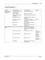
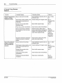
4 . Guns Not Firing ............ . . . . . . . .................. 5-2
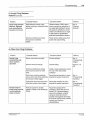
5. Guns Firing Between Patterns . ...... . . . .. . . . ........... 5-4
6. Other Gun Firing Problems ...... . . . . . . . .. . . . . ..... . ... 5-5
Section 6
Service Parts and
Reference Data
C Nordson Corporabon 1893
AI Rights Reserved
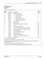
1. Introduction . . ... . . ... . ..... .. . . ........ . ... .... . .. .
2. Using the Parts List .... .. . .. ... . . . .. . . . . ... ..........
3. Service Parts ... . . ·- ... . .. . . ..... . .. ... ....... .. . .. .
PC40 Pattern Control Service Parts . . . . . . . . . . . . . . . . . . . .
4. Specifications .. . .. ... . . .. ... . . . . . . .... ... .......... .
PC40 Specifications .. .... . . . . . . . ...... . . . . ... . .. . ..
Photosensors Specifications .. . .......... . . . . .. ... ... .
6-1
6-1
6-2
6-2
6-4
6-4
6-6
PIN 103389A
57·28 1193
Section 1
Safety Summary
C N01<1son Corpora~on 1993
AI Roghts Res.,...,d
P/N 10& 389A
57-28 t/113
1-1
Safety Summary
Section 1
Safety Summary
1./ntroduction
Section 1 of the applicator manual includes safety guidelines for the
use of Nordson equipment. These guidelines apply to all operators and
service personnel working with the PC40.
•
WARNING: Allow only qualified personnel to perform
installation and troubleshooting .
In addition to the safety information in the technical manuals,
follow the specific safety precautions contained in this manual.
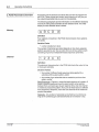
2. Explanation of Terms and
Symbols
The following safety symbols and signal words are used throughout this
publication, alerting the reader tu personal safety hazards, or identifying
conditions that can result in equipment or property damage.
WARNING: General Warning. Failure to observe can result
in personal injury or death.
WARNING: Risk of electrical shock. Failure to observe can
result in personal injury or death.
WARNING: Risk of electrocution. Disconnect equipment
from line voltage.
CAUTlON: General Caution. Failure to observe can result in
equipment damage.
NOTE: Important information.
e NOtCISOn Corporabon 1993
ADR;gms Reserved
PIN 108 389"
57· 211 1/93
1-2
Safety Summary
3. Safety During Installation
WARNING: Risk of serious personal injury or death. Failure
to follow the safety and operation information in the technical
manuals for the applicator and its associated equipment can
result in personal injury or death. Before installing, servicing,
or operating the PC40, thoroughly review Section 1, Safety
Summary, in the applicator and its associated equipment
technical manuals.
WARNING: Risk of electrocution. The AC input power line to
the PC40 unit provides voltage that can cause personal
injury or death. Before making any electrical connections,
disconnect and lock out power to the main circuit breaker for
the input power line.
PIN 10 8 389A
5 7·28 1193
Q Nordson Corporaloon 1993
All R oghiS Resarved
Section 2
Equipment Familiarization
c Norc!son Corpornon 1993
AI Rights Reserved
P/N 101138911.
57·28 1/93
Equipment Familiarization
2-1
Section 2
Equipment Familiarization
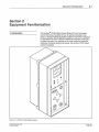
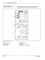
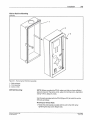
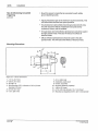
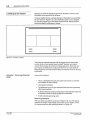
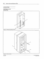
1. Introduction
The Nordson~ PC40 Pattern Control (Figure 2.1) is a time-based
control that makes it possible for you to quickly and easily set up,
select, or change material application patterns. The PC40 is designed
for applications in which material is applied to substrates moving at a
constant line speed. For applications in which material is applied to
substrates moving at varying line speeds, the Nordson PC44 Pattern
Control is required.
Figure 2. 1 - PC40 240 VAC Pattern Control
e Norclson Corpora~on 1993
Aa Rights Reserved
PIN 108 389A
57·28 1/93
2-2
Equipment Familiarization
NOTE: The PC40 240 VAC Pattern Control is designed for use only in
geographic regions where 240 VAC with a grounded neutral is the
industrial standard. If 120 VAC with a grounded neutral is the industrial
standard at your site, consider using either the PC40 AC Pattern
Control (P/N 131 712), or the PC40 DC Pattern Control (P/N 131 709)
and PS40 DC Power Supply (P/N 131 739).
NOTE: The PC40 240 VAC Pattern Control uses 220/240 VAC
solenoids to actuate pneumatic guns. The unit should not be used to
actuate electric gun .drivers. If you are using electric gun drivers, order
the PC40 DC Pattern Control (P/N 131 709) and PS40 DC Power
Supply (PIN 131 739) .
This section covers the following topics:
• A functional description of the PC40
• A description of the PC40 user interface
• A description of the four Nordson photoelectric sensors
• A description of the PC40 remote communication capabilities
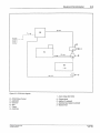
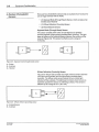
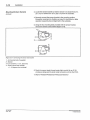
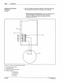
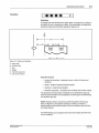
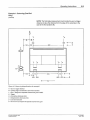
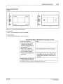
2. PC40 Functional Description
The PC40 controls the deposit of material on a moving surface
(substrate) . Figure 2.2 provides a block diagram that illustrates the
process involved.
1. A trigger device (e.g., a photoelectric sensor) senses the approach of
the leading or trailing edge of the substrate. The trigger then sends
an electrical signal to the PC40.
2. The PC40's ASIC (Application Specific Integrated Circuit) executes
the timing sequences.
3. The PC40 activates one to four output channels by sending an
electrical signal to one or more gun solenoids.
4. Air moves through the solenoid and into the extrusion gun. This lifts a
piston in the gun which allows hydraulically-fed material to flow out
of the gun onto the substrate.
5. When the user-defined pattern is completed, the PC40 stops sending
an open signal to the channel(s). The solenoid closes, airflow to the
gun piston ceases, air in the gun is released through the solenoid
exhaust, the gun piston closes, and material stops flowing to the
substrate.
PIN 108389A
57-28 1/93
c Nordson CorporalJOn 1993
All R•ghts Reserved
Equipment Familiarization
2·3
4--
B
1-~-----
I
[ID---'
l
ro
I I
c
--
s--
Jrr=r-·
~s=
I
I
G
I
--
I
\ I I
F
--2
Figure 2.2- PC40 block diagram
1 -Input voltage {240 VAC)
B - PC40 Pattern Control
C - Applicator
D -Solenoid
£-Gun
F- Trigger
G - Substrate
C Nordson Cotporation 1993
AI Righls Resetved
2 - Trigger signal
3 - Input air to solenoid
4 - Electrical input signal to solenoid
5- Material flow
PIN 108 389A
57·28 1/93
2-4
Equipment Familiarization
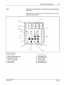
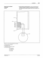
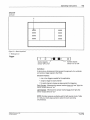
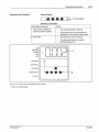
3. PC40 User Interface
The PC40 front panel (Figure 2.3) consists of an LCD, nine indicator
LEOs, six membrane push buttons, a power switch and a fuse.
PC40
15
LOCK
CONFIOUAE
1
PROOIIA._.
RIM
TEST 1-----~
MEMORY .
CHANNEL
1--------1
14
..... f. ..
-··.
1
2
.•, 3
·
13
:_~
·.
.·
'
I
2
3
4
C>
10
5
6
7
9
8
Figure 2.3 - PC40 front panel
1-LCD
2 - Output LEOs (green)
3- Set push button
4- Up pus( button
PIN 108 38SA
57·28 1/93
9 -Power switch
10 - Nordson Oval push button
11 - StattBL£0*
Gree& = power on, unit operati'!xl
0 Nordson Corporaton 1993
All Rights Aeset\'ed
Equipment Familiarization
LCD
2-5
Blue alphanumeric characters are displayed against a gray background
(Figure 2.4) .
NOTE: Rgure 2.4 is for familiarization only; these symbols are never all
displayed at the same time.
1
14
nnnn
uuuu
----
13
12
2
c D
3
10
4
3
•
4
6
Figure 2.4 - PC40 LCD
1 - Numerical display
2 - Leading or trailing edge symbols
3 - Selection level indicators
4 - Stitch bead length symbol
5 - Stitch coverage symbol
6 - Stitch on symbol
7- Stitch off symbol
c
NO<dson Corporauon 1993
ADRights Resetved
8 - Transition symbols
9 - Two-trigger symbol
10 - Single trigger symbol
11 - Channel symbols
12- Memory symbols
13 -Mode indicator arrows
14 -Lock indicator arrow
PIN 108389A
57-28 1/93
2-6
Equipment Familiarization
4. Nordson Photoelectric
Sensors
There are four photoelectric sensors that are available from Nordson for
use as trigger devices with the PC40:
• (1) Opposed Mode (Through Beam) Sensor, which consists of an
Emitter and a Receiver
• (1) Diffuse Reflective (Proximity) Sensor
• (2) Retroreflective Sensors
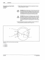
Opposed Mode (Through Beam) Sensor
This sensor consists of two units: an LED light source {emitter)
mounted· opposite a light-sensing phototransistor (receiver) . The light
beam is broken as the substrate passes between the emitter and the
receiver (Figure 2.5). This sensor is effective up to a range of
10ft (3m).
Figure 2.5 - Opposed mode (through beam) sensor
A - Emitter
B - Substrate
C-Receiver
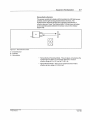
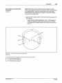
Diffuse Reflective (Proximity) Sensor
This sensor (Figure 2.6) consists of a single unit that contains both the
LED light source (emitter) and the light-sensing phototransistor
{receiver). The diffuse mode sensor detects its own emitted light
reflected off the substrate. The light beam is broken when there is no
substrate opposite the sensor (no reflecting surface) . This sensor is
effective up to a range of 15 in. (38.1 em).
Figure 2.6 - Diffuse reflective (proximity) sensor
A - Emitter/ Receiver
8- Substrate
PIN 108 389A
57·28 1/93
C Nordson CorporatiOn 1993
All Roghts Reserved
2-7
Equipment Familiarization
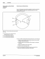
Retroreflectlve Sensors
This sensor consists of a single unit that contains the LED light source
(emitter) and the light-sensing phototransistor (receiver). The
emitter/receiver bounces its light off an opposing retroreflector or
reflective tape and "sees" the reflected light. The light beam is broken
as the substrate passes between the sensor unit and the reflector
(Figure 2.7).
Figure 2. 7 - Retroreflective sensor
A - Emitter/Receiver
B -Substrate
C - Retroreflector
• Retroreflective Polarizing Model - This anti-glare unit polarizes the
emitted light and filters out unwanted reflections. It has an
effective range of 2 in. (5.1 em) to 7ft (2.1 m) .
• Retroreflective Model - This is a non-polarized sensor that is
effective up to a range of 15ft (4.5 m) .
() Nordson Corporaoon 1993
AI Righls Reserved
PIN 108 389A
57-28 1/93
2·8
Equipment Familiarization
5. Remote Communications
Remote Memory Selection
Purpose
The PC40 has the capability to connect to a remote device which can
change the active memory. The unit can also provide +12V power for
the remote device. Wiring information for the Nordson Remote Memory
Select Switch is included in Section 3, Installation.
Remote Lock Out Interface
Purpose
The PC40 will prevent access to the PROGRAM, CONFIGURE, and
TEST modes after receiving an input signal from a remote device.
While in LOCK, programming changes cannot be made using the PC40
user interface. Wiring information for the Nordson Keyed Lock Out
Switch is included in Section 3, Installation.
Screen Display
The arrow symbol in the mode segment of the LCD will point to "LOC~
when this feature is enabled.
PIN 108389.'.
57-28 1/93
C NorGso n Corporation 1993
All Rights Reu tved
Section 3
Installation
Cl Nocdson Corporation 1993
AI Roghts Reserved
PIN 108389.4.
57-28 1/93
3-1
Installation
Section 3
Installation
1. Introduction
This chagter includes information on inspe~ing and i_nstalling the
Nordson PC40 Pattern Control and assoc1ated equ1pment:
• the gun solenoids,
• the Nordson Sensors,
• the Nordson Remote Memory Select Switch, and
• the Nordson Keyed Lock Out Switch.
2. Inspection
After unpacking, check that you have the pattern control and other
equipment that you ordered (see Section 6 for part number
information). Inspect all components for dents, cracks, scratches, or
other evidence of physical damage. If you find any damage, contact
your Nordson sales representative before installing the equipment.
3. Safety During Installation
4. Installation Tips and Hints
WARNING: Personal injury hazard. Failure to review the
safety information in Section 1, Safety Summary, of this
manual can result in equipment damage, personal injury or
death. Before installing this equipment thoroughly review
Section 1. Also, follow the specific safety precautions in this
section.
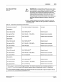
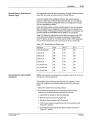
Wire Gauge
The table below specifies the proper gauge wire for the various
electrical connections, regardless of the wire length.
Table 3. 1 - Recommended Wire Guages
Cl NO<dson Corporanon 1993
AI Roghls ResO<Ved
Connection
Wire Gauge
AC
14-16
Solenoids
16-18
Remote Memory Select Switch and
Keyed Lock Out Switch
18-22
PIN 108 389A
57· 28 1/93
3-2
Installation
Avoiding Inductive Interference (Electrical Noise)
• Avoid routing wires near AC power lines, solenoid output lines,
and electrical devices such as motors, contactors; and relays.
• Use shielded cable.
• Avoid using excess wire lengths, which can act as an antenna.
Use only as much wire as needed to make connections.
limit Switches ·(it used)
• Limit switches should be wnormally closed." This will provide a
stable sensor signal.
• Limit switches can bounce when actuated. This can cause a false
trigger. De-bounce limit switches by installing a 0.1 microFarad
capacitor across the contacts.
5. Mounting the PC40 Back
Enclosure
NOTE: In order to achieve an IP-54 Enclosure Rating (splash-resistant
environment), Nordson recommends that you route all PC40 input and
output electrical connections through water-tight conduit and a junction
box. Use 1 in. (2.5 em) conduit fitting , and locate the conduit center line
1 in. (2.5 em) from the wall.
NOTE: Before mounting the PC40, make sure that you have sufficient
space to mount it. The unit is 4.0 in. wide (1 0.2 em) by 9.0 in. high (22.9
em) by 4.44 in. deep (11.3 em).
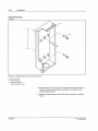
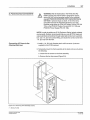
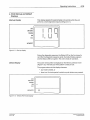
Wall or Machine Mounting
1. Loosen the six screws that secure the PC40 back enclosure to the
front assembly (Figure 3.1).
2. Pull the front assembly away from the back enclosure.
3. Set the front assembly in a safe place.
4. Position the back enclosure knockout hole for the direction the
electrical wiring will route into the PC40.
5. Place the back enclosure against the mounting surface at the
location you want to mount it.
6. Mark the centers of the two PC40 screw holes on the mounting
surface. Make sure that the center of the marks are 6 in. (15.24 em)
apart from center to cent er.
7. Drill two 7J.32 in. (5 mm) holes in the mounting surface where marked.
8. Use the two M4 x 25 mm screws, nuts, and washers provided to
fasten the back enclosure to the mounting surface (Figure 3.2).
PIN 108 389A
57·28 1/93
C Nordson Corporatoon 1993
All Roghts Reserved
3-3
Installation
Wall or Machine Mounting
(continued)
Figure 3. 1 • Removing the PC40 front assembly
1 - Back enclosure
2- Front assembly
3 - Screw {1 of 6)
DIN Rail Mounting
NOTE: Before mounting the PC40, make sure that you have sufficient
space to mount it. The unit is 4.0 in. w ide (10.2 em) by 9 .0 in. high (22.9
em) by 4.44 in. deep (11 .3 em).
Use the parts provided with the PC40 (Figure 3.3) to install the unit to
DIN rails as follows:
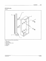
Mounting to Vertical Ralls
1. Fasten the end bracket provided with the unit to the DIN rail by
tightening the stop screw (Figure 3.3).
0 NO<dson Corpora~on 1993
AI RtghU Reserved
PIN 108 389A
57· 28 1/93
3-4
Installation
DIN Rail Mounting
(continued)
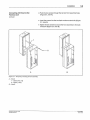
T
l
A
Figure 3.2 - Mounting PG40 to wall or machine surface
A - 6 in. (15.2 em)
1 - Back enclosure
2- Screw with washer
(nut not shown); 1 of 2
2. Use the two M4 x 12 mm screws to secure the two clips to the back
enclosure; make sure that they are oriented for mounting to the
vertical rail (Figure 3.3).
3. Fasten the back enclosure to the DIN rail by snapping the clips into
the rail.
p""
108 389A
57.28 1,'g3
C Nordson Corpora1.,n 1993
All Rogllts Res.rver:l
Installation
3-5
DIN Rail Mounting
(continued)
6
4
Figure 3.3- Mounting PC40 to vertical DIN rails
1 - Clip (1 of 2)
2 - Back enclosure
3 -Screw with washer (1 of 2)
4 -Stop screw
5- End bracket
6-DIN rail
o
NOtdson Corporabon 1993
IIJ1 Rtghts ReseJVed
PIN 106 389.\
57-28 1/93
3-6
Installation
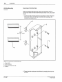
Mounting to Horizontal Ralls
DIN Rail Mounting
(continued)
Make sure that the rails are 6.0 in. (15.24 em) apart from center to
center. Also make sure that the DIN rails are at least 4.0 in. (1 0.2 em) in
length.
1. Use the two M4 x 12 mm screws to secure the two clips to the back
enclosure; make sure that they are oriented for mounting to the
horizontal rails (Figure 3.4).
1
~~'~?T
2
6.0"
~=========(~15J[cm)
'8,,
4
Figure 3.4 ·Mounting to horizontal DIN rails
1 - Clip (1 of 2)
2- Back enclosure
3 - Screw and washer {1 of 2)
4 - DIN rail
2. Fasten the back enclosure to the DIN rail by snapping the clips into
the rails.
PiN 108 389A
57· 28 1/93
Q Nordson Corporalion 1893
All Rights Reserved
3-7
Installation
6. PC40 Electrical Connections
WARNING: Risk of electrocution. The PC40 240 VAC
Pattern Control can only be used in geographic regions
where 240 VAC with a grounded neutral is the industrial
standard. Failure to connect the unit to a grounded neutral
can result in personal injury or death. If 120 VAC with a
grounded neutral is the industrial standard at your site,
consider using either the PC40 AC Pattern Control (P/N 131
712), or the PC40 DC Pattern Control (P/N 131 709) and
PS40 DC Power Supply (P/N 131 739).
NOTE: In order to achieve an IP-54 Enclosure Rating (splash-resistant
environment), Nordson recommends that you route all PC40 input and
output electrical connections through water-tight conduit and a junction
box. Use 1 in. (2.5 em) conduit fitting, and locate the conduit center line
1 in. (2.5 em) from the wall.
Connecting AC Power to the
PC40 240 VAC Unit
1. Install a 1 in. (2.5 em) diameter strain relief connector (customer
supplied) in the PC40 knockout.
2. Temporarily mount the front assembly to the back enclosure by doing
the following:
a. Loosen the six screws on the front assembly.
b. Remove the two top screws (Figure 3.5).
Figure 3.5 - Removing front assembly screws
1 - Screw {1 of 6)
o N01<1son Corpora~on 1993
A ARlghls Res..ved
PIN 108389A
57· 28 1/93
3-8
Installation
Connecting AC Power to the
PC40 ACUnit
c. Rotate the front assembly 180" (Figure 3.6).
(continued)
Figure 3.6 - Rotating the front assembly
PIN 108389A
57-28 1/93
C Nordson Corporation 1993
All R.ghts Reserved
3-9
Installation
Connecting AC Power to the
PC40ACUnit
d. Push the two screws through the top two front assembly holes
(Figure 3.7, view A).
(continued)
e. Insert the screws into the two back enclosure stand-offs (Figure
3.7, view A).
f. lighten the two screws to secure the front assembly to the back
enclosure (Figure 3.7, view 8).
A
B
Figure 3. 7- Temporary mounting of front assembly
A - ViewA
1 - Stand-off {1 of 2)
2 - Screw {1 of 2)
8 - ViewB
0 NotdSon Corpora~on 1993
AI Rognts ResetVed
PIN 108 389A
57· 28 1/93
3-1 0
Installation
Connecting AC Power to the
PC40AC Unit
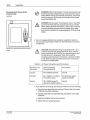
WARNING: Risk of electrocution. The AC input power line to
the PC40 provides voltage that can cause personal injury or
death. Before making any electrical connecti ons, disconnect
and lock out power to the main circuit breaker for the input
power line (Figure 3 .8}.
(cootinued)
WARNING: Shock hazard. Touching bare wires in the PC40
can result in shock that can cause personal injury or death.
When making electrical connections, make sure to strip only
as much insulation from the wires as needed. Also, make
sure that the insulation fits snugly against the PC40 terminal
blocks.
3. Use 14-16 gauge electrical wire (customer supplied) to make the
connections that are listed in Table 3.2. Terminal Block P2 is shown
in Figure 3 .9.
Figure 3.8 - Disconnect and lock out input
power
CAUTION: Reversing the wiring to connections P2-1 (L 1}
and P2-2 (Neutral) can damage the PC40. If you reverse
these connections, the PC40 will only operate properly until
the first fault on L1 (to ground). Then, the unit will be
damaged, and/or the branch circuit fuse or breaker will blow
or trip. Make sure that you wire the AC power connections
as listed in the table below.
Table 3.2 - AC Power Connections and Pin Functions
AC Power Une
Connection
PC40 Connection
Terminal Block P2
Pin Function
Ground
P2-3 ("Safety Ground")
Ground
240VAC
P2-1 ("240V L 1"}; refer to
the caution, above.
240 VAC input power
supply connection
Neutral
P2-2 ("240V Neutral"};
refer to the caution, above.
Neutral
4. If you are NOT connecting other devices at this time, do the following:
a. Grasp the front assembly with one hand . Remove the two screws
holding it to the back enclosure.
b. Carefully rotate the front assembly 180" and place it on the back
enclosure.
c. Replace and tighten the two loose screws.
d. Tighten the four remaining screws.
PiN 108 389A
57· 28 1193
c Nordson Corporation 1993
A!l Rights Rese"'e4
3-11
Installation
Connecting AC Power to the
PC40AC Unit
5. If you are connecting other devices at this time, proceed to the
appropriate installation procedure(s) in this section.
(continued)
n.
P2
P2-1
P2-2
P2- 3
P2- 4
P2- 5
P2- 6
P2-7
P2- B
P2-9
P2-10
P2-11
P2-12
llr
r--
&
&
&
I
&
&
&
&
&
&
&
&
&
....._
P1
P1-1
P 1-2
P1- 3
P1- 4
P 1-5
P1· 6
P1·7
P1· 8
p4
....---
r--
&
&
&
&
&
&
&
&
&
&
&
&
&
&
&
&
'-
'-
P4-1
P4-2
P4·3
P4· 4
P4· 5
P4-6
P4-7
P4-B
L/
0
0
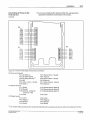
Figure 3.9- PC40 240 VAG Model terminal block connections
P2 (Power and Outputs):
P2-1 (AC 240 V L1)
P2-2 (A C 240 V Neutral)
P2 ·3 (AC Safety Ground) ( 1)
P2-4 (NC)
P2-5 (Valve 1 Return - Neutral)
P2-6 (Va lve 1)
P1 (Remote Control):
P1- 1 {Shield}
P1-2 (Ground)
P 1-3 (Common- connect to
Ground or + 12V)
PT-4 (Lock)
P4 (Trigger Inputs):
P4- 1 (+ 12V)
P4-2 (Trigger 1)
P4-3 (Ground)
P4-4 (Shield)
1
( )
P2-7 (Valve 2 Return - Neutral)
P2-8 (Valve 2)
P2·9 ( Valve 3 Return - Neutral)
P2- 10 (Valve 3)
P2- 11 (Valve 4 Return - Neutral)
P2-12 (Valve 4)
P f-5 (Remote Memory Select 3)
P1-6 (Remote Memory Select 2)
P1-7 (Remote Memory Select 1)
P1-8 (+12V)
P4-5 (+12V)
P4-6 (Trigger 2)
P4-7 (Ground)
P4-8 (Shield}
J oin multiple safety grounds (as from several AC solenoids) with a connector. wire nut, etc. before connecting th em to P2-3.
Cl NO<clsoo Corporauon 1994
All RighCs Rese<ved
PIN 108 3898
57·28
•1'9•
3-12
Installation
7. Solenoid Wiring Installation
Gun Solenoid Wiring
NOTE: The PC40 240 VAC Pattern Control uses 220/240 VAC
solenoids to actuate pneumatic guns. The unit should not be used to
actuate electric gun drivers. If you are using electric gun drivers, order
the PC40 DC Pattern Control (P/N 131 709) and PS40 DC Power
Supply (PIN 131 739}.
1. Install the gun solenoid(s} following the instructions provided in the
manual you received with your applicator.
2. If you have not already done so, temporarily mount the front
assembly to the back enclosure by doing the following:
a. Loosen the six screws on the front assembly.
b. Remove the two top screws (Figure 3.5).
c. Rotate the front assembly 1ao· (Figure 3.6).
d. Push the two screws through the top two front assembly holes
(Figure 3.7, view A).
e. Insert the two screws into the two back enclosure stand-offs
(Figure 3.7, view A).
f. 1ighten the two screws to secure the front assembly to the back
enclosure (Figure 3.7, view B).
3. Route the two leads (three if the solenoid has a ground wire) to the
PC40 through water-tight conduit (for an IP-54 enclosure rating) and
the strain relief connector.
WARNING: Risk of electrocution. The AC input power line to
the PC40 provides voltage that can cause personal injury or
death. Before making any electrical connections, disconnect
and lock out power to the main circuit breaker for the input
power line (see Figure 3.8).
WARNING: Shock hazard. Touching bare wires in the PC40
can result in shock that can cause personal injury or death.
When making electrical connections, make sure to strip only
as much insulation from the wires as needed. Also, make
sure that the insulation fits snugly against the PC40 terminal
blocks.
PiN 108 3891\
57·28 1/93
C> Nordson Corporation 1993
AJI R•ghts Reserved
3-13
Installation
Gun Solenoid Wiring
(continued)
!
WARNING: Burns. Unexpected gun firing can occur during
PC40 installation. The firing can be a response to trigger
signals caused by foreign objects blocking the sensors, and
by intentional and unintentional triggering that can occur
during maintenance. Nordson recommends that you install
quick-disconnect solenoid leads. Disconnect the leads
during installation to disable the solenoid. Users may want to
provide an additional measure of safety by disabling the
trigger.
4. Use 16-18 gauge electrical wire (customer supplied) to make the
connections shown in Table 3.4. See Figure 3.9 for the location of
terminal block P2.
Table 3.4 - Solenoid Pin Connections and Functions
1
Solenoid ConnectionC
>
PC40 Terminal Block-Pin Connection
Function
Solenoid #1:
Ground (if present)
P2-3 ("GROUND") (2)
Solenoid ground
One lead to PC40
P2-5 ("VALVE 1 - RETURN")
Solenoid return connection
One lead to PC40
P2-6 ("VALVE 1")
Solenoid source connection
Ground (if present)
P2-3 ("GROUND") (2)
Solenoid ground
One lead to PC40
P2-7 ("VALVE 2 - RETURN")
Solenoid return connection
One lead to PC40
P2-8 ("VALVE 2")
Solenoid source connection
Ground (if present)
P2-3 ("GROUND") (2)
Solenoid ground
One lead to PC40
P2-9 ("VALVE 3 - RETURN")
Solenoid return connection
One lead to PC40
P2-10 ("VALVE 3")
Solenoid source connection
Ground (if present)
P2-3 ("GROUND") <2>
Solenoid ground
One lead to PC40
P2- 11 ("VALVE 4- RETURN")
Solenoid return connection
One lead to PC40
P2-12 ("VALVE 4")
Solenoid source connection
Solenoid #2:
Solenoid #3:
Solenoid #4:
{I)
2
(l
Some patterns require more than eight transitions. Two channel outputs can be connected in parallel to a
solenoid. Then you can program both channels' transition values in sequence for a total of 16 transitions.
If all fou r solenoid grounds are present, they will not all fit onto P2-3. Connect all the grounds together using a
connector, wire nut, etc. before connecting to P2-3.
C NO<dson C<>rpora~on 1993
AI Rights Res"""'d
PIN 108 389A
57· 28 1/93
3-14
/nstalfation
5. If you are NOT connecting other devices at this time, do the following:
Gun Solenoid Wiring
(ccntinued)
a. Grasp the front assembly with one hand. Remove the two screws
holding it to the back enclosure.
b. Carefully rotate the front assembly
enclosure.
1so• and place it on the back
c. Replace and tighten the two loose screws.
d. lighten the four remaining screws.
6. If you are connecting other devices at this time, proceed-to the
appropriate installation procedure(s) in this section.
8. Trigger (Sensor) Installation
Trigger Input Pin Characterization
The trigger devices, usually photosensors, are connected to PC40
terminal block P4 (refer to Table 3.6 and see Figure 3.9). The signals
from the trigger are resistively coupled and filtered into the PC44.
Table 3.6- Trigger Pin Characterization
Terminal Block-Pin
Connection
Function
Trigger #1
P4-1 ("+12V")
DC power for first trigger. Maximum current available
from +12 V is 500 mA. This is the maximum current
available for all connections to +12 V including those
loads on other PC40 connectors.
P4-2 ("TRIGGER 1")
Input signal from first trigger.
P4-3 ("GROUND")
Ground connection for first trigger.
P4-4 ("SHIELD")
Shield connection for first trigger.
Trigger #2 (if used),
PiN 108 389A
57-28 1/9 3
P4-5 ("+ 12V")
DC power for second trigger. Maximum current
available from + 12 V is 500 rnA. This is the maximum
current available for all connections to + 12 V including
those loads on other PC40 connectors.
P4-6 ("TRIGGER 2")
Input signal from second trigger.
P4-7 ("GROUND")
Ground for second trigger.
P4-8 ("SHIELD")
Shield connection for second trigger.
C> Nordson Corpora1ion 1993
AJI Aogh1s Aeurved
Installation
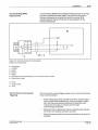
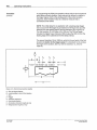
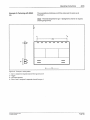
Current Sinking (NPN)
Requirements
3-15
A current sinking (NPN) device capable of sinking at least 10 rnA must
be used to stimulate the signal inputs. The internal circuitry for the
Nordson photosensor is pre-wired to include the required NPN
switching element. Figure 3.10 shows the wiring diagram for the
Nordson photosensor.
B
- 8
1
IIIII
k
A
II Ill
2
3
4
!
t"" ~
I
I
~
T
-
*
~
7
Figure 3. 10 - Nordson photosensor wiring diagram
(wired as a sinking device)
A -Photosensor
1- +12VDC
2-Signal
3-Ground
4 -Shield
5- Switching element (NPN transistor), pre-wired within sensor circuitry
6 - Pigtail wire for shield
B - PC40
7- To logic circuit
8 - +12V
Tips for Minimizing Unwanted
Triggering
The occurence of unwanted trigger signals can be reduced by following
these recommendations:
• Avoid routing sensor wires near AC power lines, solenoid output
lines, or other electrical devices (i.e., motors, contactors, relays,
etc.) that may cause electrical interference. Especially avoid
routing wires in troughs or conduits with other high
current-carrying conductors.
• Make sure that no objects other than the substrate pass between
the sensor and substrate during line operation.
• Mount the sensors within the recommended distance range of the
substrate.
C NOI'clson Corpotabon 1993
AI Aoghts Aeser.red
P/N 108 389A
57·28 1/93
3-16
Installation
Tips for Minimizing Unwanted
Triggering
• Mount the sensor to metal that is connected to earth safety
ground (system ground).
(continued)
• Adjust photosensor gain to the minimum required sensitivity. This
will reduce both electrical and optical problems.
• The photosensor cable shield should be grounded at both ends.
This will reduce the effects of electrical noise produced by
contactors, motors, and arc-welders.
• Through-beam and retroreflective photosensors should be used in
the light operate mode. This also will reduce the effects of
electrical noise.
• Diffuse reflective photosensors should be used in the dark
operate mode. This will reduce the effects of electrical noise.
Mounting Dimensions
.
'
'
13
Figure 3. 11 - Sensor dimensions
1 - 1.21 in. (30.7 mm)
2- 0.95 in. (24. 1 mm)
3 - 30 ft (9. 1 m)
4 - Mounting peg; 0.25 in. diameter x 0. 10 in. (6.4 mm
diameter x 2.5 mm)
5 - 0.75 in (19. 1 mm)
6 - 1.5 in. (38. 1 mm)
PIN 108 389A
57·28 1/93
7-2.1 in. (53.3 mm)
8 - Gasketed, acrylic cover
9 - 0.48 in. (12.2 mm)
10- 114 screw clearance (2 places)
11 - 1.08 in. {27.4 mm)
12- 0. 71 in. {18 mm) diameter; 18 x 1 mm thread
13- Mounting nut (supplied), 0.95 in. (24. 1 mm) diameter
o Notdson CotPOtallon 19ll3
All Rlgncs ReS"tved
3-17
Installation
Mounting Dimensions
(continued)
Figure 3. 12 - Sensor bracket dimensions
1-0. 10 in. (2.5 mm)
2 - 0. 79 in. (20. 1 mm)
3- 1.79 in. (45.5 mm)
4 - 90 degrees
5 - 0.80 in. (20.3 mm)
6 - 10 degrees (typically)
Mounting Nordson Sensors
7- 0. 170 in. (4.3 mm); 2 slots
8 - 1.25 in. (31.8 mm)
9- 15 degrees (either direction)
10-0. 120 in. (3. 1 mm)
11 - 0.120 in. (3.1 mm)
1. If you have not already done so, temporarily mount the PC40 front
assembly to the back enclosure by doing the following:
a. Loosen the six screws on the front assembly.
b. Remove the two top screws {Figure 3.5).
c. Rotate the front assembly 180" {Figure 3.6).
d. Push the two screws through the top two front assembly holes
{Figure 3.7, view A).
e. Insert the two screws into the two back enclosure stand-offs
(Figure 3.7, view A).
f. lighten the two screws to secure the front assembly to the back
e~closure (Figure 3.7, view B) .
2. Check the intended mounting position to make sure that there
enough space to mount the sensor(s) and bracket(s). See Figure
3.11, Figure 3.12 and Figure 3.13.
3. Proceed to the instructions for mounting the type of sensor that you
are using.
Mounting Diffuse Sensors
1. Check the intended mounting position to ensure that there is enough
space to mount the sensor(s) and bracket(s) . See Figure 3.11 ,
Figure 3.12, and Figure 3.13.
2. Check the intended mounting position to make sure that there are no
objects other than the substrate that will pass between the sensor
and substrate during line operation.
Q Na<CSon Corporaijon 1993
AURightS Reserved
PiN 108 389A
57-28 1/93
3-18
Installation
Mounting Nordson Sensors
(continued)
3. Locate the sensor bracket so that the sensor Is no closer than 2 in.
(5.1 em) nor further than 15 in. (38.1 em) from the substrate.
4. Securely connect the sensor bracket to the mounting surface.
Excessive movement or vibration can result in intermittent or false
operation caused by loss of alignment to the substrate.
5. Using the two mounting bolts provided with the sensor bracket,
secure the sensor to the bracket (Figure 3.13).
Figure 3. 13 - Connecting the sensor and bracket
1 - 114 mounting bolts (2 supplied)
2 - Bracket
3 -Lens centerline, 1. 12 in. (28.5 mm)
4 -Front of sensor tilts vertically
+I- 15 degrees from horizontal
6. Route the sensor leads through water-tight conduit (for an IP-54
enclosure rating} and the strain relief connector and into the PC40.
7. Skip to "Nordson Photosensor Wiring Connections."
PIN 108 38!1A
57·U I/SI3
o Norason Corporallon 1993
All Aoghts Aoservoa
3-19
Installation
Mounting Nordson Sensors
Mounting Opposed Sensors
(continued)
NOTE: To avoid unwanted trigger signals, make sure that there are no
objects other than the substrate that pass between the emitter and
receiver during line operation. Also, make sure that the emitter and
receiver are mounted no more than 10ft (3 m) from each other.
1. Check the intended mounting position to ensure that there is enough
space to mount the sensor(s} and bracket(s}. See Figure 3.11,
Figure 3 .12, and Figure 3.13
2. Check the intended mounting position to make sure that there are no
objects other than the substrate that will pass between the sensor
and substrate during line operation.
3. Locate the emitter bracket so that the emitter is no further than 10 ft
(304.8 em) from the substrate.
4. Securely connect the emitter bracket to the mounting surface.
Excessive movement or vibration can result in intermittent or false
operation caused by loss of alignment to the substrate.
5. Securely connect the receiver bracket to the mounting surface.
6. Using the two mounting bolts provided with the brackets, secure the
emitter and receiver to their respective brackets (Figure 3.13).
7. Route the sensor leads through water-tight conduit (for an IP-54
enclosure rating) and the strain relief connector and into the PC40.
8. Skip to "Nordson Photosensor Wiring Connections."
C Nordson Corpora Don 1993
AU R•ghts ResOlVed
PIN 108 38911.
57· 28 1/93
3-20
Installation
Mounting Nordson Sensors
Mounting Retroreflectlve Sensors
(continued)
NOTE: To avoid unwanted trigger signals, make sure that there are no
objects other than the substrate that pass between the emitter/receiver
and the reflector during line operation.
NOTE: Make sure that the emitter/receiver and reflector are mounted
no more than 7 ft (2.13 m) from each other {polarized model) or no
more than 15ft {4.5 m) from each other {non-polarized model).
1. Check the intended mounting position to ensure that there is enough
space to mount the sensor(s) and bracket(s). See Figure 3. 11,
Figure 3.12, and Figure 3.13
2. Check the intended mounting position to make sure that there are no
objects other than the substrate that will pass between the sensor
and substrate during line operation.
3. Locate the emitter/receiver bracket so that it is no further from the
reflector than
a. 7 ft (2.13 m) for the polarized model, or
b. 15ft (4.5 m) for the non-polarized model.
4 . Securely connect the emitter/receiver bracket to the mounting
surface. Excessive movement or vibration can result in
intermittent or false operation caused by loss of alignment to the
substrate.
5. Using the two mounting bolts provided with the bracket, secure the
emitter/receiver to the bracket (Figure 3.13).
6. Secure the reflector to the mounting surface opposite the
emitter/receiver.
7. Route the sensor leads through water-tight conduit (for an lP-54
enclosure rating) and the strain relief connector and into the PC40.
8. Skip to "Nordson Photosensor Wiring Connections."
PIN 108 389A
57· 28 1/93
C> Nordson Corporalion 1993
Aft Rtghts ReseNed
Installation
Nordson Photosensor Wiring
Connections
3-21
WARNING: Risk of electrocution. The AC input power line to
the PC40 provides voltage that can cause personal injury or
death. Before making any electrical connections, disconnect
and lock out power to the main circuit breaker for the input
power line (see Figure 3.8).
1. Connect the wires for each photosensor as indicated in Table 3.7 or
Table 3.8. See Figure 3.9 for the location of terminal block P4.
Table 3. 7 - Nordson Photosensor Wire Connections (except Throughbeam Emitter, PIN 131 473)
Wire Color
Function
Trigger #1 Connection
Trigger #2 (if used)
Terminal Connection
Red
+VDC
P4-1 ("+12V"}
P4-5 ("+ 12V")
Green
Sourcing output
None; clip lead.
None; clip lead.
White
Sinking output
P4-2 ("TRIGGER 1"}
P4-6 ("TRIGGER 2")
Black
Common
P4-3 ("GROUNDj
P4-7 ("GROUNDj
Table 3.8- Nordson Through-beam Emitter, PIN 131 473
Wire Color Code
Wire Color
Function
Trigger #1
Terminal Connection
Trigger #2 (if used)
Terminal Connection
Brown
+VDC
P4-1 ("+12V")
P4-5 (" + 12V")
Blue
Common
P4-3 ("GROUNDj
P4-7 ("GROUNDj
2. Ground the other end of each photosensor shield near the sensor.
3. If you are NOT connecting remote devices at this time, do the
following:
a. Grasp the front assembly with one hand. Remove the two screws
holding it to the back enclosure.
b. Carefully rotate the front assembly 180" and place it on the back
enclosure.
c. Replace and tighten the two loose screws.
d. Tighten the four remaining screws.
4. Align the sensors by following the instructions that follow.
e NO<dson
Corpora~on
AI Rig hls Res - d
1993
PIN 108 389A
57-28 1/93
3·22
Installation
Alignment Indicator
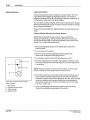
Aligning Sensors
Nordson photosensors have an alignment indicator (LED) . The LED
pulse (flash) rate increases as alignment improves. The sensor is
adjusted so that the LED is off (not flashing) in the dark condition or is
on (flashing) at a fast rate in the light condition.
The LED flash rate also indicates when sensor maintenance is needed.
Whenever the flash rate is slow, the sensor's lenses should be cleaned
and the alignment checked.
Proceed to the instructions for aligning the type of sensor that you are
using.
Aligning Diffuse Reflective (Proximity) Sensors
NOTE: Before adjusting the gain control, make sure that any
background objects (e.g., moving machine parts which would pass
through the sensor's field of view during operation) are present in the
sensor's line of sight during adjustment.
1. Remove the gasketed acrylic cover located above the sensor
electrical cable.
2. Turn on power to the sensor.
3. Direct the infrared sensor light beam at the substrate and
observe the red alignment LED (Figure 3.14).
4. Turn the gain control until the LED is flashing on and off.
.....,...+----1
4----.;..·0
.....,.....>-!--- 2
3
0
Figure 3. 14 -Alignment LED and gain
control locations
1 - Gain control
2- Light/dark operate switch
3 - Cable opening
4 -Alignment L£0
PIN 108 389A
57·28 1193
5. Move the substrate and, if possible, any background objects out of
the sensor's field of view. If the LED stays off, no further adjustment
is necessary.
NOTE: The gain control is a 15-turn pot which does not have a stop
position. The gain control ratchets at the end of its travel.
6. If the LED remains on, turn the gain control counterclockwise by 1..2
turn increments until the sensor comes on only when it "sees" the
substrate, but goes off when the substrate is removed. If the LED still
remains on after you turn the gain control fully counterclockwise,
remount the sensor further from the substrate (but no further away
than 15 in. or 38.1 em).
7. If you are connecting other devices at this time, proceed to the
appropriate installation procedure(s) in this section.
C> Nordson Corpora tion 1993
All Rights Reserved
3-23
Installation
Aligning Sensors
Aligning Opposed (Through Beam) Sensors
(continued)
1. Remove the gasketed acrylic cover located above the sensor
electrical cable.
2. Turn on power to the sensor.
3. Direct the emitter at the receiver and observe the red alignment LED
on the receiver (Figure 3.14).
4. Turn the gain control to the fully clockwise position. The LED should
be flashing on and off.
5. Adjust the position of the emitter and/or receiver to achieve the
maximum alignment LED flash rate.
6. Move the substrate between the emitter and receiver. If the LED
stays off, no further adjustment is necessary.
7. If the LED continues to flash on and off, or remains on, turn the gain
control counterclockwise by 1~ turn increments until the LED goes
out and stays off.
8. If you are connecting other devices at this time, proceed to the
appropriate installation procedt,Jre(s) in this section.
Aligning Retroreflectlve Sensors
1. Remove the gasketed acrylic cover located above the sensor
electrical cable.
2. Turn on power to the sensor.
3. Direct the infrared light beam on the emitter/receiver at the reflector
and observe the red alignment LED (Figure 3.14).
4. Turn the gain control to the fully clockwise position. The LED should
be flashing on and off.
5. Move the substrate between the emitter/receiver and reflector. If the
LED stays off, no further adjustment is necessary.
6. If the LED continues to flash on and off, or remains on, turn the gain
control counterclockwise by ,~ turn increments until the LED goes
out and stays off. If the LED still remains on after you tum the gain
control fully counterclockwise, take steps to reduce the reflectivity of
the substrate.
7. If you are connecting other devices at this time, proceed to the
appropriate installation procedure(s) in this section.
C'J NO<dson Corpornon 1993
AI Right$ Res..ved
PIN 108 389A
57· 28 1/93
3-24
Installation
9. PC40 Remote
Communications Installation
The following information is provided if you will be using a remote
device to select active memory and/or lock out input through the PC40
user interface.
Remote connections are made to PC40 terminal block P1 (Figure 3.9) .
Signals connected to P1 are optically isolated from the remote system.
The opto-isolators can be turned on by either current sourcing or
current sinking devices.
Remote Pin Characterization
Table 3~ 9 - Remote Communication Pin Characterization
Pin
Function
Comments
P1-1 ("Shield")
Provided for field wiring convenience.·
Connected to the remote device 1/0
printed circuit board.
P1-2 ("Ground")
Provided for field wiring convenience.
Connected to the remote device 1/0
printed circuit board.
P1 -3 ("Common")
Provides for one half of the connection for
all of the opto-isolators.
For sourcing (PNP) devices, P1-3 should
be connected to P1-2 ("Ground") . For
sinking (NPN) devices, P1-3 should be
connected to P1-8 ("+12V").
Pl-4 ("lock")
Provides for a remote signal to disallow
access to the PC40 Program Mode.
P1-5 ("Remote
Memory Select 3")
Provides connection to allow a remote
device to change the active memory.
P1 -6 ("Remote
Memory Select 2")
Provides connection to allow a remote
device to change the active memory.
P1-7 ("Remote
Memory Select 1")
Provides connection to allow a remote
device to change the active memory.
P1-8 {"+1 2V")
Provides 12 VDC input power for any
remote device that requires it.
PIN 108389A
57-28 11!13
Maximum current available from pin P1 -8
is 500 mA.This is the maximum current
available for all connections to pin P1 -8
including loads on other PC40 connectors.
C Nord son Corporation 1993
All R 1g~ts Reserved
3·25
Installation
Remote Memory Selection and
Memory Logic
The logic levels should be held continuously. Remote selection will take
place after the levels have been there for at least 500 ms.
If you try to select a non-configured memory, the current memory
remains in effect and the PC40 status LED will light red. The LED will
stay on until you select a configured memory or configure the memory
you were attempting to select.
When the PC40 senses a remote memory selection, the unit checks to
see if any patterns are in progress. If no patterns are in progress, the
memory change will take place. However, if a pattern is in progress, the
memory change will be inhibited until all patterns are completed.
Table 3.1 0 shows the logic that is used to select a memory. Logic OFF
or ON refers to the state of the device connected to PC40 terminal
block P1 (pins 5, 6, and 7). The device can be NPN or PNP depending
on how P1-3 is wired (refer to the comments for P1-3 in Table 3.9).
Table 3. 10 - Remote Memory Select Logic
Remote Memory Select Switch
Installation
Selection
P1-5
P1-6
P1-7
Remote Disabled
Off
Off
Off
Memory A
Off
Off
On
Memory B
Off
On
Off
Memory C
Off
On
On
Memory D
On
Off
Off
For Future Use
On
Off
On
For Future Use
On
On
Off
For Future Use
On
On
On
NOTE: This switch is not intended to be installed in the PC40. It can be
mounted on a remote panel, etc.
The Nordson Remote Memory Select Switch is a 4-position, rotary
switch that enables you to remotely select which PC40 memory is
active.
1. Secure the switch to the mounting surface.
2. If you have not already done so, temporarily mount the front
assembly to the back enclosure by doing the following:
a. Loosen the six screws on the front assembly.
b. Remove the two top screws (Figure 3.5).
c. Rotate the front assembly 180" (Figure 3 .6).
d. Push the two screws through the top two front assembly holes
(Figure 3.7, view A).
e. Insert the two screws into the two back enclosure stand-offs
(Figure 3.7, view A.)
~
Nordson Corporaoon 1993
A a R o ~hl$ Aeoorvcd
PIN 108 389A
57·28 1/93
3-26
Installation
Remote Memory Select Switch
Installation
f. lighten the two screws to secure the front assembly to the back
enclosure (Figure 3.7, View B).
(continued)
WARNING: Risk of electrocution. The AC input power line to
the PC40 240 VAC power supply) provides voltage that can
cause personal injury or death. Before making any electrical
connections, disconnect and lock out power to the main
circuit breaker for the input power line (see Figure 3.8).
WARNING: Shock hazard. Touching bare wires in the PC40
can result in shock that can cause personal injury or death.
When making electrical connections, make sure to strip only
as much insulation from the wires as needed. Also, make
sure that the insulation fits snugly against the PC40 terminal
blocks.
3. Use 18-22 gauge wire (customer supplied) to make the switch and
PC40 jumper wire connections shown in Figure 3.15.
2
A
3
Figure 3. 15 - Memory select switch {rear view) jumper
connections
1 - Jumper 111
2 - Jumper 112
3 - Jumper 113
PIN
10838~
57· 28 1/93
Cl NOfdson COrporoooon 1993
All Atgh ts Reserved
Installation
Remote Memory Select Switch
Installation
(continued)
3-27
NOTE: When both the Rotary Select Switch and Keyed Lock Out
Switch are installed, both must be connected as either sourcing devices
or as sinking devices. Figure 3.16 shows the wiring for the Rotary
Select Switch as a sourcing device. Figure 3.17 shows the wiring for
the switch as a sinking device.
4. Make the Rotary Select Switch to PC40 connections by doing one of
the following:
• Switch Used as a Sourcing Device - Use an 18·22 gauge wire
(customer supplied) to make the connections shown in Figure
3 .16. Make sure to Install the jumper from PC40 connection P1·2
to P1·3.
A
c
Figure 3. 16 • Current sourcing remote memory switch
(rear view)
A- P1-8 ("+12'V); also, install jumper from PC40 connection P1-2 to Pt-3
B - P1-7 ("Remote Memory Select 1")
C- Pt-6 ("Remote Memory Select 2")
D - Pt -5 ("Remote Memory Select 3")
0 Natdson Corporabon 1993
AI Rights Resetved
PIN 108 389A
S7-28 1/93
3-28
Installation
Remote Memory Select Switch
Installation
Switch Used as a Sinking Device
(continued)
Use an 18-22 gauge wire (customer supplied) to make the connections
shown in Figure 3.17. Make sure to install the jumper from PC40
connection P1 -3 to P1-8.
A
c
Figure 3. 17 - Current sinking remote memory switch
(rear view)
A - P1-2 (Groundj; also, install jumper from
PC40 connection P1-3 to P1-8
8- P1 -7 ("Remote Memory Select 1?
C- P1-6 ("Remote Memory Select 2j
D.- P1-5 (Remote Memory Select 3"r
5. If you are NOT connecting other devices at this time, do the following:
a. Grasp the front assembly with one hand. Remove the two screws
holding it to the back enclosure.
b. Carefully rotate the front assembly 180" and place it on the back
enclosure.
c. Replace and tighten the two loose screws.
d. Tighten the four remaining screws.
6. If you are connecting other devices at this time, proceed to the
appropriate installation procedure(s) in this section.
PIN 108 389A
57·28 1193
C Nordson Corporation 1993
All R1ghts Reserved
3-29
Installation
Keyed Lock Out Switch
Installation
NOTE: This switch is not intended to be installed in the PC40. It can be
mounted on a remote panel, etc.
The Nordson Keyed Lock Out Switch is an A-lock type, 4-tumbler
switch that prevents any input via the PC40 user interface.
NOTE: When both the Keyed Lock Out Switch and Rotary Select
Switch are installed, both must be connected as either sourcing devices
or as sinking devices. Figure 3.18 shows the wiring for the Keyed Lock
Out Switch as a sourcing device. Figure 3.19 shows the wiring for the
switch as a sinking device.
1. Secure the switch to the mounting surface.
2. If you have not already done so, temporarily mount the front
assembly to the back enclosure by doing the following:
a. Loosen the six screws on the front assembly.
b. Remove the two top screws (Figure 3.5).
c. Rotate the front assembly 1eo• (Figure 3.6).
d. Push the two screws through the top two front assembly holes
(Figure 3.7, view A).
e. Insert the two screws into the two back enclosure stand-offs
(Figure 3.7, view A) .
f. Tighten the two screws to secure the front assembly to the back
enclosure (Figure 3.7, view B).
WARNING: Risk of electrocution. The AC input power line to
the PC40 provides voltage that can cause personal injury or
death . Before making any electrical connections, disconnect
and lock out power to the main circuit breaker for the input
power line (Figure 3.8) .
WARNING: Shock hazard. Touching bare wires in the PC40
can result in shock that can cause personal injury or death.
When making electrical connections, make sure to strip only
as much insulation from the wires as needed. Also, make
sure that the insulation fits snugly against the PC40 terminal
blocks.
Cl NO<dson Corporation 1993
M Rights Reserved
PIN 108 389A
57-28 1/93
3-30
Installation
Keyed Lock Out Switch
Installation
3. Use 18-22 gauge wire (customer supplied) to make the switch and
PC40 jumper wire connections by doing one of the following
(ccntinued)
• Switch Used as a Sourcing Device - Use an 18-22 gauge wire
{customer supplied) to make the connections shown in
Figure 3.1 8. Make sure to install the jumper from PC40
connection P1-2 to P1-3.
0
A
P1
P1-1
P1-2
P1-3
P1-4
P1-5
P1-6
P1·7
P1-8
~---------+4------8
0
0
Figure 3. 18 - Current sourcing keyed lock out switch
A - Front assembly (rear view)
B - Install jumper wire
C - Keyed lock out switch (rear view)
P1 {Remote Control"):
Pt -2 ("Ground)
P t ·3 ("Common•)
P1-4 ("Lock?
Pt-8 ("+12Vj
PIN 108389A
57·28 1153
Cl Nordsoo Corporallon 1993
All Roghts Reserv-.1
Installation
Keyed Lock Out Switch
Installation
3-31
• Switch Used as a Sinking Device - Use an 18-22 gauge wire
(customer supplied) to make the connections shown in Figure
3.19. Make sure to install the jumper from PC40 connection P1-3
to P1 -8.
(continued)
0
A
P1-1
P1-2
P1-3
P1-4
P1-5
P1·6
P1-7
P1·8
0
B
Figure 3.19- Current sinking keyed lock out switch
A - Front assembly (rear view)
B -Install jumper wire
C - Keyed lock out switch (rear view)
Pt ("Remote Control"):
P 1-2 ("Ground}
P1 -3 ("Common")
P1-4 ("Lock}
P1·8 ("+12V")
0 Not<!Son Corpora don 1993
AI Roghls Res.....ed
PIN 108 389A
57·28 1/93
3-32
Installation
Keyed Lock Out Switch
Installation
4. If you are NOT connecting other devices at this time, do the following:
(continued)
a. Grasp the front assembly with one hand. Remove the two screws
holding it to the back enclosure.
b. Carefully rotate the front assembly
enclosure.
1ao• and place it on the back
c. Replace and tighten the two loose screws.
d. Tighten the four remaining screws.
5. If you are connecting other devices at this time, proceed to the
appropriate procedure(s) in this section.
PIN 104 389A
57-28 1/93
C Nordson Corporaloon 1993
All Rogh1s Rese"'ed
Section 4
Operating Instructions
0 NO<dson Corporaoon 1993
AI Rogh1S Reserved
PIN 108 389A
57·281/93
4-1
Operating Instructions
Section 4
Operating Instructions
1./ntroduction
Through descriptions and examples, this section will provide the tools
that will help you identify what patterns you want and how to get those
patterns. ·
In "PC40 Parameters Overview~ we will define the terminology
associated with pattern control and identify the decision factors that you
will consider when setting up your application pattern.
In "Setting Up the Pattern" you are given a step-by-step procedure for
measuring your pattern, calculating values and making decisions which
will be required when you program the PC40. A pattern log is provided
at the end of the section. You can use copies for recording your choices
and values in preparation for programming.
In "PC40 Start-up and Default Displays" you will become familiar with
the power-up and normal operation displays that you will see.
In "Program Mode," "Run Mode," and "Configure Mode," you will learn
which buttons to press to make selections and enter the values that you
calculated in setting up your pattern. You will also learn how to
eliminate unneeded parameters to make programming as easy as your
application.
In "Test Mode" you will learn how to access this mode. You will also
learn how to use TEST when you need to manually fire or purge the
guns.
Throughout this section, the Nordson Oval push button will be referred
to as the "Nordson Oval"; the Set push button as "SET''; and the four
arrow-shaped push buttons as "UP," "DOWN ," "LEFT," and "RIGHT."
C NOfdson Corpora~on 1993
"-1 Roghls RooO<V•d
PIN 108 389A
57· 28 1/93
4-2
Operating Instructions
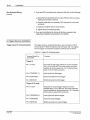
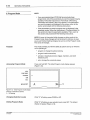
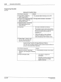
2. PC40 Parameters Overview
Parameters are the choices and values that you have to program into
the PC40. These choices and values, when properly set, will give you
the material bead pattern (s} you want on the substrate.
The following paragraphs provide information on the different decisions
involved in setting each parameter at each selection level. The initial
display for each selection level is shown.
Memory
lAB C D
XI
Definition
Four registers or locations in the PC40 microcomputer where patterns
are saved.
Decision Factor
• number of patterns to store
The number of memories you select depends on how many separate
patterns you plan to use. You can store from one to four patterns each
consisting of up to four independent bead sequences (channels} .
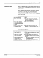
Channel
11 2 3 4
xl
Definition:
The electronic timing circuitry in the PC40 that directs the output of one
or more gun solenoids.
Decision Factors
• the number of different bead sequences being applied to a
substrate within a given pattern, and/or
• the number of gun solenoids that are needed to put down that
pattern, and/or
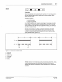
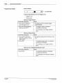
Bead Sequences - Figure 4.1 shows the bead sequence of a pattern. If
beads in parallel sequences have the same length, same spacing
between them, and same gun-to-gun response time, only one channel
is needed to produce the pattern . If any one of these factors is different
from sequence to sequence, more than one channel will be needed to
produce the pattern.
Solenoids - Any number of solenoids can be fired by one channel as
long as the combined gun solenoid demands do not exceed 1 amp.
P/N 108 389A
57· 28 1/93
C)
Nord son Corporation 1993
All Roghts Reserved
4-3
Operating Instructions
Channel
(continued)
1
----
--
--
-
Figure 4. 1 - Bead sequences
1 - Bead (gun on)
Trigger
1
~
2
J
~
Symbol depicts
sensor "off' to won"
~
xl
Symbol depicts
sensor "on" to "off'
Definition:
A device (e.g., photosensor) that senses the approach of a substrate
and sends a trigger signal to the PC40.
Decision Factors:
• one or two triggers needed for the application
• assign a trigger to each channel
• for each channel, choose an edge symbol for triggering
Dark Operate - Whenever the sensor receiver does not "see" light, the
sensor output device is "on."
light Operate - Whenever the sensor receiver does usee" light, the
sensor output device is "on."
--
NOTE: Nordson sensors are factory-set for light operate mode. Table
4.1 tells you which edge symbol to select for each operating
circumstance.
Cl N O<d$on Corporation 1993
AI
Rtg~l$
Rese<Vecl
PIN 108 389A
57· 28 1193
4-4
Operating Instructions
Trigger
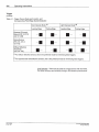
(continued)
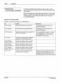
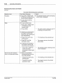
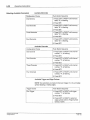
Table 4. 1 - Trigger Device Mode and Location, and
Corresponding PC40 Edge Symbol Selection
Dark Operate Mode <1>
Ught Operate Mode <2>
Leading Edge
Leading Edge
Trailing Edge
Trailing Edge
Opposed (ThroughBeam) (P/N 131 473
and 131 486)
Retroreflective
(P/N 131 474 or
131 475)
Diffuse Reflective
(Proximity)
(P/N 131 476)
Ill For diffuse reflective sensors, this is the preferred mode for minimizing false triggers.
121For opposed and retroreflective sensors, this is the preferred mode for minimizing false triggers.
Limit Switches - These can be used as a trigger device with the PC40.
For better accuracy and reliability, though, use Nordson photosensors.
PIN 108J89A
57· 28 1/93
C) No rd son Corporal oo n 1993
All Roghls Reserved
4-5
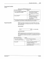
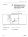
Operating Instructions
Transition
X
Definition:
A change from one in.terval to the other: either a change from a delay to
a duration or from a duration to a delay. The combination of delays and
durations makes up a transition sequence (Figure 4.2).
2
Q
I
I
I
I·
I·
1
0
A
3
-
~B~
-
..----4-- Figure 4.2- Delays and durations
A - Delay (Off)
B1234-
Duration (On)
Gun
Trigger
Transition sequence
Line travel direction
Decision Factors:
• number of transitions - dependent upon number of delays and
durations
• delays - lengths of spaces between beads
• durations - material bead lengths
• transition set-points - cumulative sum of delay and duration values
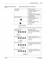
The placement of every bead of material on the substrate requires at
least two time intervals to be completed: one delay (gun off) followed by
one duration (gun on).
NOTE: Nordson timers commonly use the first pattern interval as a
delay. In Figure 4.2, the pattern consists of a delay, a duration, a
second delay, and a second duration. Each new pattern starts with the
first delay interval.
The PC40 allows you to program from one to four delays and from one
to four durations.
C NOtdson Corporation 1993
AI R1ghts Reserved
PIN 108 389A
57·28 1/93
4-6
Operating Instructions
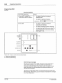
Transition
In programming the PC40, the transition values refer to the end-point of
each delay and each duration. Each end-point is defined in relation to
the trigger signal, which is the starting point of the entire transition
sequence. Each transition value is a distance measure that is
converted to time values.
(continued)
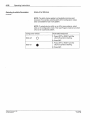
NOTE: The initial delay for an application with a leading edge trigger
has to account for the trigger to gun distance (A in Figure 4.3) plus the
distance from the leading edge to the first transition (Bin Figure 4.3).
The first transition (f1) in Figure 4.3 is 700 ms. The 700 ms length
includes the trigger to gun interval of 400 ms plus the 300 ms from the
leading edge of the substrate to the first delay interval.
The second transition (f2) is 1000 ms, which is the end point of the first
duration In relation to the trigger signal. It is important not to confuse
the length of the duration, 300 ms, with the transition, T2, which is
1000 ms.
2
0
:
T,
A--i: s700r
T2
1
1000
T3
T..
1
1
1600 1900
.___ 5
.___ 6
c::;:p
1
14-------
3
·'
.._--4--Figure 4.3 - Determining transition lengths
A8 123456-
Gun to trigger distance
Leading edge to start of first duration
Gun
Trigger
Transition sequence
Line travel direction
Cumulative transition lengths (in ms)
Delay/duration lengths (in ms)
PIN 108389A
57-28 1/93
C1 Nord son Corporabon 1993
All Roghts R eS<Irved
4-7
Operating Instructions
IO
Stitch
Definition:
•
xl
Material application with a duration that consists of a repeating pattern
of short material beads (stitch lengths) with uniform spaces (stitch
gaps) between them.
Decision Factors:
• material savings
• pattern requirement
In the stitch level, you can select a percentage of coverage and stitch
bead length for a given duration. Selecting less than 100% coverage
during durations may still meet your application needs, plus allow you
to save on material costs.
During each duration in a pattern, a bead of material is deposited.
However, when stitching is selected, this bead is broken up into a
number of smaller beads (stitch lengths) with uniform spaces (stitch
gaps) between them (Figure 4.4).
... . . . ,____ 5_ _ __,..~1 · · ·
""'1
..~----- 5 ----i...
-.jr..._--s-~~~
1----.. II- - - - - - - - ·
2-:r I
I
3
I
I
I
I
-
I
--I
I
I
Figure 4.4 - Continuous and stitch beads
1 - Stitch off
2 - Stitch on
3 - Stitch length
4 - Stitch gap
5 -Duration
6 - De/ay
NOTE: Stitch is not intended to provide precise bead placement. If you
need precise placement of small beads, channels can be used in
parallel with stitch off to achieve up to 32 transitions (for 4 channels in
parallel) .
C NOIOSon Corporabon 1993
AI Roghts Rese<ved
PIN 108 389A
57·28 1/93
4-8
Operating Instructions
3. Setting Up the Pattern
Because the PC40 is digitally programmed, all pattern values can be
calculated and programmed in advance.
It may be helpful to draw a simple diagram of the pattern you want (like
the one shown in Figure 4.5). Leave sufficient space on your diagram
for recording trigger to gun and bead measurements. Measurements
should be made in millimeters or inches.
--
--
Figure 4.5- Example 1 pattern
The following example assumes that the trigger and an appropriate
number of guns have already been installed. Typically, one output
channel fires one gun to produce one bead sequence. More than one
gun may be controlled by an output channel if two or more identical
bead sequences are required and if the gun response times do not vary
significantly.
Example 1: Cartoning {One End
Only)
Assume the following:
• This is a dedicated line (only one carton size will be run with the
same pattern for each carton).
• Line speed is constant.
• The difference in gun-to-gun response time does not significantly
effect bead positions.
• A diffuse reflective sensor is being used in dark operate mode and
is located to sense the leading edge of the substrate.
• 8 watt solenoids are being used.
Measuring Distances
After you draw your pattern (as shown in Figure 4.5), you will need to
measure the length of each delay and duration of your pattern. Write
the measurements on the drawing as shown in Figure 4.6.
P.t1108389A
57·28 1193
C Nordson CorporatiOn 1993
All R1ghts Reserved
4-9
Operating Instructions
Example 1: Cartoning (One End
Only)
(continued)
NOTE: The first delay measurement must include the gun to trigger
distance (A) plus the distance from the edge of the substrate to the
start of the first duration (B).
2
0
I
I
I
I
A~I
I
I
T2
T1
Bl
I
850
250
150-1100
I
I
I
,.
.,
600
3
..-- 4
I
1
T1
I
I
I
~ ~
...
T;s
T2
I
I
--
I
I
I
I
li
I
T4
I
I
I
r. .
I
t 7 5 ..·- - - - - 500 - l 7 5
75
1
225 300
BOO 875
t--4
3
,._- -5- -Figure 4.6- Measuring delays/ durations for example 1
A - Gun to- trigger distance
B - Leading edge of substrate to start of first duration
1 - Gun 1; assigned to separate channel from guns 2 and 3
2 - Trigger
3 - Cumulative distances (mm)
4 - Delay/duration distances (mm)
5 - Line travel direction
6 - Guns 2 and 3; assigned to separate channel from gun 1
0 Nordson Corporabon 1993
AI RlghiO Raserved
PIN 108389A
57· 28 1/93
4-1 0
Operating Instructions
Example 1: Cartoning (One End
Only)
(continued)
Converting Distance Measurements to Tlme Values
Each of the distances must be converted to time values.
1. Measure the conveyor fine speed. (l)
•
Metric: measure in meters per minute (m/min)
•
English: measure in feet per minute (ftlmin)
2. Use the appropriate formula to convert each measurement to a time value. (2)
0 ·06 ~ ~is~nce)mm) - Time in seconds
me pee
•
Metric:
•
English:
5 x Distance {in.) Ti
.
d
L.
d
- 1me m secon s
me 5 pee
3. Calculate all the transition values for your pattern by adding up the delays
and durations. Write them on your pattern drawing.
<'> For this example, the line speed is 45.7 m/min (150ft/min).
2
< > In
the gun 1 bead in this example, the first delay (T1) includes the gun to
trigger distance of 150 mm plus the 100 mm distance from the substrate
edge to the start of the first duration. This cumulative distance {250 mm) was
then converted using the Metric formula:
0.06x250mm
• 0.328 seconds (328 ms)
. mfmin
45 7
In the two lower bead sequences, the first delay (T1) includes the gun to trigger distance of 150 mm plus the 75 mm distance from the substrate edge to
the start of the first duration. This cumulative distance {225 mm) was then
converted using the Metric formula:
0.06x 225 mm
. mfmln -0.295 seconds (295 ms)
45 7
PiN 108 389A
57·28 1/93
C> Nordson CorporatiOn 1993
All Roghls Reserved
Operating Instructions
4-11
Example 1: Cartoning (One End
Only)
(continued)
Illustrated Pattern Parameters- Figure 4.7 shows the converted time
values (transitions) for this example. Figure 4.8 shows how the
parameters are recorded on the pattern log for this example.
2
Q
'I
:
T1
A-i 8I
I
197
I
328
1116
~ 131 141•--------788- -- -- --.-1•1
...
3
---4
1
T1
I
T3
T2
I
I
-~,.,~ ...r.-·l.
I
I
'
I
I
I
I
-I
I
I
I
---i r. .
I
·-----656
T4
295 393
I
--4
98
1049
1147
3
...,._--5--Figure 4.7- Example 1 transitions changed to time values
A - Gun to trigger distance
8 - Leading edge of substrate to start of first duration
1- Gun 1, assigned to separate channel from guns 2 and 3
2 - Trigger
3456-
Cumulative time values (in ms)
Separate delay/duration time inteNals (in ms)
Line travel direction
Guns 2 and 3; assigned to separate channel from gun 1
C Nordson Corpora bon 1993
AU RightS ResOlVed
P/N 108 389A
57·28 1/113
4-12
Operating Instructions
Programming Decision Factors for This Example:
Example 1: Cartoning (One End
Only)
{continued)
Memory - One memory is needed. Memory 8 is circled on the
pattern log, but any configured memory could be selected.
Channel - Two channels are needed because:
• Two gun solenoids are used (one for gun 1, and one for guns 2
and 3) .
• There are two sets of transition values. Even though there are
three bead sequences, the lower two have identical transition
values.
Channels 1 and 2 are circled on the pattern log.
Trigger - Only one trigger is needed. The diffuse sensor is being used in
dark operate mode and is mounted to sense the leading edge of the
substrate. By referring to Table 4.1, the appropriate edge symbol was
determined. That symbol is circled on the pattern log for both channels.
Transition
• Two transitions are needed for the gun 1 bead shown in the
Figure 4.6: one delay and one duration. The values are written on
the pattern log for channel 1.
• Four transitions are needed for the gun 2 and 3 bead sequences:
two delays and two durations. The values are written on the
pattern log for channels 2 and 3.
Stitch - This pattern does not require stitching, so the stitch off symbol
is checked on the pattern log for both channels. Example 2, which
follows, shows a pattern that requires stitching.
MEMORY (C IRCLE ON E}
G)
G)
TRIGGER {CIRCLE ONE)
TRANSITIONS
(vALu Es)
@
A
CHANNEL
-
I
I
1
(ON)
CD
TR IGGER (CIRCLE ONE)
-
Y.
-
(0 - 1007.)
10
(OFF}
EDGE SYMBOL
(CIRCLE ONE)
2
•h -
(VALUEs) 295 1393
-
• .
®
CHANNEL
STITCH
-- s•
•
~ ~ _I _I _I _ I _I _ I
-
(OFF}
TRANSITIONS
D
EDGE SYM BOL
(CIRCLE ONE}
2
_LO -
STITCH
c
0491t 1471
(ON}
....
s
•
_ I _ I _I _I
Y..
-•
-
I
-•
_I
(0 -1.023)
I
-
(0-1 00 ~ )
(0-1.023)
-~
Figure 4.8 - Pattern log for example 1
PIN 108 389A
57-28 1/93
0 Nordson Corporatoon 1993
All Aighls Reserved
4-13
Operating Instructions
Example 2: Cartoning with Stitch
On
The assumptions, distances, and time values are the same as in
Example 1.
Stitch- The bead sequence for gun 1 (assigned to channel 1) requires
stitching (figure 4.9).
2
Q
T1
~~·---------------788------------~·1
1
- - - - - - - -
--
-----3---
Figure 4.9 - Example 2: stitch pattern
1 - Gun 1: assigned to separate channel from guns 2 and 3
2- Trigger
3 - Une travel direction
4 - Guns 2 and 3; assigned to separate channel from gun 1
C> Nor&on Corpora~on 1993
Aft A1gh1S Aese<Ved
PIN 108 389A
57·28 1/93
4-14
Operating Instructions
Determining Maximum Stitch Bead Length - We determined this value
using the following general rule:
Example 2: Cartoning with
Stitch On
(continued)
Duration length (in seconds) x 0.20- Max. stitch bead length (in
seconds)
In this example, the maximum stitch bead length is 0.158 seconds:
•
• 0.788x 0.20-0.1576 seconds (157.6 ms)
We rounded the value to 0.158 seconds {158 ms). The PC40 stitch
capability would allow us to specify stitch beads as long as 0.158
seconds each.
However, we wanted more and shorter stitch beads for our application.
We ran several test patterns and got the following results.
Number of Beads
Stitch Bead Lengths
at 50% Coverage
0.050
8
0.060
7
0.070
6
0.082
5
Based on the test patterns and our application, we specified beads
0.050 seconds long at 50% coverage. These values were recorded on
the pattern log (Figure 4.10).
Stitch on was programmed and noted on the pattern log for channel 1.
MEMORY (C IRCLE ONE)
(V
(V
CHANNEL
TRIGGER (CIRCLE ONE)
TRANSITIONS
(VALuEs) 328
STITCH
I
-
®
A
2
I
-
I
.....
-
0 ,/ •
-
~
X
-
I
(VALUES) 2951393
,/
(OFF)
2
-
{ON)
I
o.oso I
EDGE SYMBOL
(CIRCLE ON£)
--9
I
-
I
_ I _I
• - X
j, 049j, 1471
0 -
I
(0-1.023)
®
(!)
~
(0 - 10m0
{ON)
TRIGGER (CI RCLE ONE)
~
I
b1161_ I _ I _ I _I
CHANNEL
STITCH
0
EDGE SYMBOL
(C IRCLE ONE)
-
(OFF)
TRANSITIONS
c
(0 - 1OOlr.)
-
I
I
I
_I
(0-1.023)
Figure 4.10- Pattern log for example 2
PIN 108389A
57-28 1/9 3
C Nordson Corporatoon 1993
All R1ghts Reserved
Operating Instructions
4-15
4. PC40 Start-up and Default
Displays
Start-up Display
This display appears for approximately 2-3 seconds while the unit
performs a short diagnostic sequence (Figure 4.11 ).
-I I I- I
LOCK
I
I • I- I I
CONFIGURE
PROGRAM
RUN
TEST
MEMORY
Figure 4. 11- Start-up display
During the diagnostic sequence. the Status LED on the front panel is
red. After the diagnostic sequence ends, the default display appears
and the Status LED turns green. The unit is ready for operation.
Default Display
The active memory letter is displayed on the Memory selection level
(Figure 4.12). This tells you which pattern is ready to use.
The program returns to this display whenever:
• any mode is exited, or
• there is a 10 minute period in which no push buttons are pressed.
LOCK
CONFIGURE
PROGRAM
RUN
+
TEST
t.4E t.4 0RY
A
Figure 4. 12 • Default (RUN mode) display
PIN t548tBA
57· 28 t/93
0 Nordson Corporaloon 1993
AJI R1ghls Reserved
4-16
Operating Instructions
NOTE:
5. Program Mode
• If you are programming a PC40 that has previously been
programmed, not all the parameters you want to program may be
available. Follow the instructions in "Run Mode" (uReviewing
Parameters and Values") later in this section. If the parameters
you want to program are displayed in the review, return to this
section and proceed with the following instructions.
• If the parameters you want to program are not displayed in the
parameter review, follow the instructions in "Configure Mode" (in
this section) to make the parameters available. Then, return to
this section and proceed with the following instructions.
NOTE: If power is interrupted while changes are being made in the
Program mode, those changes will not be stored in memory. As soon
as you are finished making changes, be sure to exit the Program mode.
This saves all changes.
This mode provides you with the ability at system start-up or while the
unit is operating to
Purpose
• program or change the active memory;
• program inactive memories;
• activate or deactivate channel, trigger, transition, and stitch
selections; and
• set or change the numerical values.
Accessing Program Mode
LOCK
CONFIGURE
PROGRAM
RUN
TEST
ME:MORY
Press and hold SET. The initial Program mode display appears
(Figure 4.13).
~
A
v_
/\
1
Figure 4. 13 - Initial Program mode display
(memory A selected as acti ve)
1flashing
·x·
Changing Selection Levels
While "X" is flashing, press DOWN or UP.
Exiting Program Mode
While "X" is flashing on any selection level, press SET. The default
display will appear (Figure 4.12) .
PIN t 08 38!1.>.
57·28 l/93
Cl Nordson Corporalion t 993
All Rrghts Reserved
Operating Instructions
Programming Memory
4-17
NOTE: Only one memory letter is initially displayed (Figure 4.13). This
is the active memory. You can program the active memory or any of the
inactive memories.
NOTE: Changes you make to the active memory pattern take effect
in-process with the next trigger signal. During set-up, press the
Nordson Oval to activate changes made between trial patterns.
Changes to inactive memories can be stored for later use. Changes are
not saved as you make them. To save changes in memory, you must
exit the Program mode.
Changing the Active Memory
Push Button Sequence
: Result
1. Press and hold SET.
1. The active memory letter is displayed
constantly (not flashing) . "X" is flashing on
the memory selection level.
2. Press LEFT or RIGHT to
move to the letter that you
want to select as the active
memory.
2. The memory letter is flashing.
3 . Press the Nordson Oval to
activate that memory.
3. The letter is displayed constantly (not
flashing); "X'' flash ing at the Memory level.
Selecting a Memory to Program
Push Button Sequence
Result
1. Press and hold SET.
1. Initial Program mode display shown (Figure
4.13, above) .
2. Press LEFT or RIGHT to
select a memory letter.
2. The active memory letter is replaced by a
flashing letter indicating the current selection
position.
3. When the desired memory is
flashing, press SET to
program the parameters.
PIN 154 8 18A
57·28 1193
•
The program automatically moves to the
Channel selection level.
•
"X" is flashing at the right of the level.
C Nordson Corporalion 1993
All Rights Reserved
4-18
Operating Instructions
Programming Channel
1
2
3
4
~I
(FLASHING)
Default Display
Programming Selections for the Channel level
• the number of channels
Selecting A Channel for Programming (1)
Push Button Sequence
Result
1. Press LEFT or RIGHT to
move to the channel number
that you want to program
1. The channel number is flashing.
2. Press SET.
2. The channel number stays on constantly
(without flashing).
•
The program automatically moves to the
Trigger selection level.
•
"X" is flashing at the right of the level.
Ill Activated or deactivated channels can be programmed.
The Difference Between Activated and Deactivated Channels
Activated channels are those that are turned on (provide gun output) for
a selected memory. Deactivated channels are those that are turned off
(provide no gun output).
The PC40 has four memories, each of which can save one pattern.
However, it is possible to save more than one pattern per memory
if some of the patterns require less than four channel outputs. Figure
4.14 shows an example of how this can be done by deactivating and
reactivating channels. By keeping channels 1 and 4 activated, and
deactivating channels 2 and 3, you could save and use the pattern in
View A. By deactivating channels 1 and 4, and reactivating channels 2
and 3, you could save and use the pattern in Vtew B.
NOTE: Only the channels that are activated for a memory are shown in
the Channel selection level display.
NOTE: When reactivating and deactivating channels, previously
programmed values are maintained.
PIN
10838~
57·28 1193
C> Nord son Corporatoon 1993
All R oghlS Raserve<l
Operating Instructions
4-19
Programming Channel
(continued)
2
1
B
A
Figure 4. 14 - Activating/deactivating examples
A - First pattern
1 - Guns: 1 and 4 activated; guns 2 and 3 deactivated
8 - Second pattern
2 - Guns: 2 and 3 activated; guns 1 and 4 deactivated
Programming Steps to Reactivate or Deactivate a Channel
Push Button Sequence
Result
1. Look at the initial Channel
selection level display to
determine which channel(s)
are activated (1l·
2. Press LEFT or RIGHT to
move to the channel number
that you want to change.
2. The selected channel number is flashing.
3 . Press UP and DOWN at the
same time.
3. The program remains in the Channel level
and displays the new active channel. The
channel state, activated or deactivated, is
reversed.
4. Repeat steps 1 through 3 to
change additional channels.
1
C)
PIN 154 81V.
57-28 1/93
Activated channel numbers are displayed on the LCD.
0 Nordson CorporatiOn 1993
All Rights Reserved
4-20
Operating Instructions
Programming Trigger
Default Display
~I
1
(FLASHING)
Programming Selections for the Trigger Level
• T rigger 1 or 2
• Edge symbol
Making a Trigger Choice
Push Button Sequence
Result
1. Press LEFT or RIGHT to
move to trigger 1 or 2.
1. The display shows the selected trigger
number flashing.
2. When the desired trigger is
flashing, press SET.
•
The trigger number is displayed
constantly (not flashing}.
•
"X" is flashing on the Trigger selection
level.
Making an Edge Choice
Push Button Sequence
Result
1. Press LEFT or RIGHT to
select the leading or trailing
edge symbol.
1. The selected edge symbol is flashing on the
LCD.
2. Press SET.
.
•
The selected edge symbol is displayed
constantly (not flashing}.
"X" is flashing on the Trigger selection
level.
Moving to the TRANSITION Selection Level
Push Button Sequence
Press DOWN.
PIN 108 389A
57-28 1/93
Result
•
The transition symbols are displayed
constantly (not flashing}.
•
"X" is flashing on the Transition selection
level.
C> Nordson Corporalion 1993
All A•atns Reserved
Operating Instructions
Programming Transition ·
4-21
Default Display
Selecting a Transition
Push Button Sequence
Result
1. Press LEFT or RIGHT to
select a transition symbol.
2. Press SET.
LOCK
CONFIGURE
PROGRAM
RUN
CHANNEL
TRIGGER
The selected symbol is flashing .
•
The current value for that transition is
displayed in the numerical display area.
•
•
The selected symbol is flashing .
The right-most digit of the value is
flashing (Figure 4.15).
nnn
+
1
U.UUL
TEST
M EMORY
•
A
1
1
TRANSITION
-II
2
STITCH
Figure 4. 15 - Program mode TRANSITION value display
1 - Right-most digit flashing
Nordson Corporatoon 1993
AI Rrghts Res8Mid
PIN 108 389A
57-28 1193
4-22
Operating Instructions
Programming Transition
(continued)
Setting the Transition Value
Push Button Sequence
Result
1. Press LEFT or RIGHT to
select a digit position.
1. The selected digit is flashing on the LCD.
2. Press UP (to increase the digit 2. The digit value increases or decreases.
value) or press DOWN (to
decrease the·value).
3. Repeat the steps 1 and 2 until
all the digits are set to the
value you want.
4. Press SET.
•
The value is entered into memory.
•
The program moves to the next transition
symbol to the right (which is flashing; and
the current value for the transition is
displayed), or
•
If this is the eighth or last configured
transition, the program moves to "X",
which is flashing on the Transition level.
5. Repeat steps 1 though 4 until
you have the values that you
want for all the transitions.
Implementing Transition Changes Between Patterns
You may want to enable changes to these values between patterns in
set-up or during intermittent operation.
Push Button Sequence
Result
1. The transitions are set to new values.
1. Repeat the steps in "Selecting a
Transition" and "Setting the Transition
Value."
2. Press the Nordson Oval.
•
.
PIN 108 389A
57·28 1/93
The pattern in progress is
interrupted.
Operation resumes (using the new
values) when the next trigger
signal is received .
Nordson Corpor atKin 1993
All Atghts Reserved
4-23
Operating Instructions
Programming Transition
(continued)
Moving to the STITCH Selection Level
Result
Push Button Sequence
1. If "X: is not flashing on the Transition
level, press LEFT or RIGHT.
2. Press DOWN.(1)
•
The transition symbols flash as
you press LEFT or RIGHT
•
"X" is flashing on the Transition
level.
•
The stitch symbol is displayed
constantly (not flashing) .
•
"X" is flashing on the Stitch
selection level.
Ill The program will not allow you to access Stitch mode if you selected Stitch Off
in the Configure mode. Refer to "Configure Mode" later in this section.
Programming Stitch
NOTE: The program will not allow you to access Stitch mode if you
selected Stitch Off in the Configure mode. Refer to "Configure Mode"
later in this section.
Default Display
0
(FLASHING)
Deactivating Stitch
NOTE: Deactivating stitch turns stitching off for the channel that you
are programming. However, the values for % coverage and bead length
are still saved in memory for later use if you reactivate stitch for this
channel.
Push Button Sequence
Result
1. Press LEFT or RIGHT to
move to the stitch off symbol.
1. The stitch off symbol is flashing:
2. Press SET.
(flASHING)
.
•
Nordson Cotporatoon 1993
AU Aoghl.s Re served
I· 0
I
The stitch off symbol is displayed
constantly (not flashing).
"X" is flashing on the Stitch level (see the
default display above) .
PIN 108 389A
57-28 1/93
4-24
Operating Instructions
Programming Stitch
(continued)
Reactivating Stitch
Result
Push Button Sequence
1. Press LEFT or RIGHT to
move to the stitch on symbol.
•
The stitch off symbol is displayed
constantly and
•
The stitch on symbol is flashing:
I
(rUSHING)
2. Press SET.
LOCK
CONFIGURE
PROGRAI-4
RUH
TEST
t.1Et.10RY
CHANNEL
TRIGGER
The stitch on symbol is displayed
constantly (not flashing).
•
•
The stitch percentage symbol is flashing .
The right-most digit of the current stitch %
value is flashing in the numerical display
area (Figure 4.16).
I II
1
uu
A
1
1
I
•
-+
·•
-II
TRANSITION
•
STITCH
X
2
Figure 4. 16- Program mode, stitch percentage display
1 -Right-most digit flashing
2 -Percent symbol flashing
Determining % Coverage
You can set coverage from 0-1 00%. Of course, if you select 0% or
some other small value, you will have either no stitch beads or
extremely small stitch beads. If you select 100% coverage or some
other large value, you will have either one continuous bead or an·
almost continuous bead.
To achieve a useful stitch pattern, we recommend that you begin with
50% coverage. From there, you can increase or decrease the coverage
to suit your application.
p~ 108389A
57·28 1/93
Nordson Corporation 1993
All Roght.s Resel\led
4-25
Operating Instructions
Programming Stitch
(ccntinued)
Entering % Coverage Values
Push Button Sequence
Result
1. If the setting is 100% and you
want to set it to a lower
percentage:
a . Press LEFT or RIGHT to
move to the left-most digit.
a. The left-most digit is flashing.
b. Press DOWN.
b. The value changes to 0.
2. Press LEFT or RIGHT to
select a digit position.
2. The selected digit is flashing on the LCD.
3. Press UP (to increase the digit 3. The digit value increases or decreases.
value) or press DOWN (to
decrease the value) .
4. Press SET.
LOCI
COHfl~URE
PROGRAH
RUN
TEST
~EMORY
CHANNEL
TRIGGER
TRANSITION
STITCH
+
•
The percentage value is saved in
memory.
•
•
The stitch bead length symbol is flashing,
The current bead length value is
disp:ayed, and the right-most digit is
flashing (Figure 4.17)
1-1 n1-1 l
~ 1
U.l_ll_l_j
A
1
1
•••---• ••
2
Figure 4. 17- Program mode, stitch bead display
1 - Right·most digit flashing
2 - Bead symbol flashing
Nord :.on Corporation 199J
AI Rights Reserved
PIN 108 389A
57-28 1/93
4·26
Operating Instructions
Programming Stitch
(continued)
Determining Stitch Bead Length
This setting defines the length of each stitch bead that will be deposited
during each stitched duration. You can set the length from 0 to 1.023
seconds per bead.
Similar to setting % values, selecting a very small stitch bead value will
result in an almost continuous bead and may exceed the mechanical
response time capabilities of the gun and solenoid. Depending on how
large a stitch bead value is selected, you may have only one bead
deposited during any duration.
To achieve a useful stitch pattern, Nordson recommends that you begin
with a stitch bead that equals 115 of the duration length (unless you
have other specific requirements). For example, a 0.500 second
duration should have no more than a 0.100 second stitch bead lengths.
Based on test patterns, you can then increase or decrease the bead
length to suit your application.
Entering Bead Length Values
Push Button Sequence
Result
1. Press LEFT or RIGHT to
select a digit position.
1. The selected digit is flashing on the LCD.
2. Press UP (to increase the digit 2. The digit value increases or decreases.
value) or press DOWN (to
decrease the value).
3. Repeat the steps 1 and 2 until
bead length is set to the value
you want.
4. Press SET.
PIN 108 389A
57·28 1/93
4. "X" is flashing on the Stitch level.
Nordson Corpora110n 1993
All Roghls Resetved
Operating Instructions
4-27
6. Run Mode
Run Mode enables you to
Purpose
• reset the pattern and to
• review the programmed parameters and values.
This is the PC40 operational mode. You must be in this mode in order
to access any other mode or to view program parameters.
After start-up, the PC40 automatically defaults to this mode. The unit
returns to this mode whenever:
Accessing Run Mode
• SET is pressed while
·x· is flashing in any selection level,
• there is a 10 minute period in which no push buttons are pressed.
Resetting the Pattern
Press the Nordson Oval to reset the pattern. The pattern will restart
when the PC40 receives the next trigger signal.
Reviewing Parameters and Values
The selections programmed for each available memory can be
reviewed in the Run mode.
Parameter Review Sequence
Selection Level
Push Button Sequence
Result
Memory
1. Press DOWN.
1. The LCD displays the active memory;
is flash ing on the Memory level.
2. Press LEFT or RIGHT until
the memory symbol that you
want to review is flashing.
2. The selected memory letter is flashing.
3. Press SET.
Channel
4. Press LEFT or RIGHT until
the channel symbol that you
want to review is flashing.
5. Press SET.
PIN 108 389A
57·28 1/93
·x·
•
The selected memory letter is
displayed constantly on (not flashing).
•
The active channel numbers for this
memory are displayed.
•
·x· is flashing on the Channel level.
4. The selected channel number is flashing
and the memory letter is displayed.
•
The selected memory letter is
displayed.
•
The channel number is displayed .
•
The trigger and edge symbol are
displayed.
•
The transition symbols are displayed
is flashing on the Transition
and
selection level.
·x·
C Nordson Corporation 1993
All A•ghts Reserved
4-28
Operating Instructions
Reviewing Parameters and Values
(continued)
Parameter Review Sequence (continued)
Selection Level
Push Button Sequence
Result
Transition
6. Press LEFT or RIGHT until
the transition symbol that you
want to review is flashing.
6. The selected transition symbol is flashing
and its value is displayed.
7. To view other transitions,
repeat step 6.
Stitch
8. To view the Stitch level:
a. Press LEFT or RIGHT until
"X" is flashing on the
transition level.
·x·
•
The stitch symbol is displayed and
is flashing on the Stitch level.
a. Press UP to move to any
previous level.
•
•x• is flashing on the selected level.
b. Press SET to exit the
parameter review.
•
The program returns to the default
(Run) mode.
•
The selected symbol is flashing and its
value is displayed.
b. Press DOWN.
9. If stitching was deactivated in
the Program mode for the
channel you are reviewing, do
one of the following:
10. If stitching was activated in
the Program mode for the
channel you are reviewing :
•
Move to any other selection
level, or exit parameter review.
Cl Nordson Corporabon 1993
AURights Reserved
Press LEFT or RIGHT to
move to the stitch
percentage or bead length
symbol.
11 . When you are finished
viewing the Stitch level, do
one of the following:
•
Press UP to move to any
previous level.
•
Press SET to exit the
parameter review.
.
•
·x· is flashing on the selected level.
The program returns to the default
(Run) mode.
P/N 108 389A
57·28 1193
4·29
Operating Instructions
7. Configure Mode
CAUTION: Removing memories in Configure mode erases
all parameter values for those memories. Removing
parameters can erase programmed values for some or all
memories and/or channels. Only the parameters you select
in Configure will be accessible in the Program and Run
modes. Nordson recommends that Configure mode be
utilized only in initial set-up or for intended system
modification. To routinely activate and deactivate
parameters, use the Program mode.
Purpose
This mode gives you the ability to:
• select the number of memories available for programming, and to
• select the parameters available for programming.
Accessing Configuration Mode
Press the Nordson Oval and SET buttons at the same time. The
Configuration mode display is shown (Figure 4.18).
LOCK
CONFIGURE
PROGRAM
RUN
TEST
MEMORY
CHANNEL
TRIGGER
8
2
A
1
1
C D
3 4
X+:-:----1
2 -II II-
TRANSITION
STITCH
•
Figure 4. 18- Configuration mode defaults
1-
·x· flashing
Changing Selection Levels
While •x• is flashing, press DOWN or UP.
Exiting Configure
While
P/N 108 389A
57-28 1/93
·x· is flashing, press SET.
C Nordson CorporatiOn 1993
AJI Alghto Reserved
4-30
Operating Instructions
Selecting Available Parameters
Available Memories
Configuration Choice
Push Button Sequence
One Memory
1. Press LEFT or RIGHT until memory
letter, "A", is flashing .
2. Press SET.
Two Memories
1. Press LEFT or RIGHT until memory
letter, "B", is flashing.
2. Press SET.
Three Memories
1. Press LEFT or RIGHT until memory
letter, •c•, is flashing.
2 . Press SET.
Four Memories
1. Press LEFT or RIGHT until memory
letter, ·o•, is flashing.
2. Press SET.
Available Channels
Configuration Choice
Push Button Sequence
One Channel
1. Press LEFT or RIGHT until channel
number, "1", is flashing.
2. Press SET.
Two Channels
1. Press LEFT or RIGHT until channel
number, "2", is flashing.
2. Press SET.
Three Channels
1. Press LEFT or RIGHT until channel
number, "3", is flashing.
2. Press SET.
Four Channels
1. Press LEFT or RIGHT until channel
number, "4", is flashing.
2. Press SET.
Available Trigger and Edge Choices
NOTE: Two selections are made in this level: trigger (1 or 2), and edge
symbol (leading or trailing edge} .
Trigger Choice
Push Button Sequence
One Trigger
1. Press LEFT or RIGHT until trigger
number, "1", is flashing.
2. Press SET.
3. Press LEFT or RIGHT to select an
edge symbol (refer to "Edge Symbol
Choice, • below.
C NO<dson Corporuon 1993
AI Rlgh1s Reserved
P/N 108 389A
57-28 1/93
Operating Instructions
4-31
Available Trigger and Edge Choices (continued)
Selecting Available Parameters
(continued)
Trigger Choice
Push Button Sequence
Two Triggers
1. Press LEFT or RIGHT until trigger
number, "2", is flashing.
2. Press SET.
3. Press LEFT or RIGHT to select an
edge symbol (refer to "Edge Symbol
Choice," below).
Edge Symbol Choice
Push Button Sequence
1. Press LEFT or RIGHT until the
symbol is flashing.
-II
2. Press SET.
---
1. Press LEFT or RIGHT until the
symbol is flashing.
2. Press SET.
Available Transitions
NOTE: Transitions are made available in pairs (one delay and duration) .
Configuration Choice
Push Button Sequence
One Transition Pair:
1. Press LEFT or RIGHT until the
left-most transition pair is flashing.
2. Press SET.
y
(FLASHING)
1. Press LEFT or RIGHT until the
second transition pair from the left is
flashing .
·
Two Transition Pairs:
y
2. Press SET.
(FLASHING)
Three Transition Pairs:
1. Press LEFT or RIGHT until the third
transition pair from the left is flashing.
2 . Press SET.
y
(FLASHING)
Four Transition Pairs:
1. Press LEFT or RIGHT until the
right-most transition pair is flashing.
y
2. Press SET.
(FLASHING)
P/1'1 108389A
57-28 1/93
C Nordson Corporaton 1993
All A1ghts Aosorved
4-32
Operating Instructions
Selecting Available Parameters
Stitch-off or Stitch-on
(continued)
NOTE: The stitch choice applies to all available memories and
channels. For example, selecting stitch-off in Configuration makes
stitch unavailable for use in any pattern.
NOTE: To selectively turn stitch on or off for some patterns, select
stitch-on in Configuration mode. Then use Program mode to turn stitch
off or on for a particular pattern.
Configuration Choice
Stitch-off
Stitch-on
o NO<dson Corporation 1993
AI R•ghls Reserved
0
e
Push Button Sequence
1. Press LEFT or RIGHT until the
stitch-off symbol is flashing.
2. Press SET.
1. Press LEFT or RIGHT until the
stitch-on symbol is flashing.
2. Press SET.
PIN 108 389A
57· 28 1/93
Section 5
Troubleshooting
C NOtdson Corpora~on 1993
AI Rrghts Resetved
PIN 108 389A
57-28 1/93
5-1
Troubleshooting
Section 5
Troubleshooting
1. Introduction
In this section you wilt find fault isolation and correction procedures.
Obvious causes of malfunction, such as broken wires, missing or loose
fasteners, etc. should be noted during daily visual inspection and
corrected immediately.
2. Safety Precautions
WARNING: Before performing any troubleshooting
procedures, thoroughly review Section 1, Safety Summary,
in this manual. Only qualified personnel are to perform any
troubleshooting procedures.
WARNING: Even when switched off, Nordson applicators
and the PC40 contain electrical potentials that can cause
death. Before opening any of these units to check or make
electrical connections, disconnect and lock out input
electrical power.
3. Troubleshooting Checklist
Following Initial Installation
Check for the items listed below if the PC40 is not operating after you
initially install it:
• proper power,
• PC40 power switch in the on position,
• PC40 fuse good, and
• correct sensor selected.
If the unit still is not operating, go to the detailed troubleshooting
procedures that follow in this section.
0 NO<dson Corporacon 1993
AI Righ1s Re served
P/N 108 38 9A
57· 28 1/93
5-2
Troubleshooting
4. Guns Not Firing
Problem
PC40 status LED red.
(NOTE: It is normal for
this LED to light red at
unit power-up. After a
brief self-test, it will
light green.)
Possible Reason
Selecting an unconfigured
memory via remote memory
select line.
Select configured memory or
make unconfigured memory
available.
PC 40 has failed internal
diagnostics check.
Replace unit; contact your
Nordson representative.
PC40 status LED dark. Power switch in OFF position.
PC40 output LED(s)
lighting.
PiN 108 389A
57·28 1/93
Corrective Action
Refer to
Sec. 4,
wconfigure
Mode".
Move switch to ON postion.
Defective fuse.
Check; replace if necessary.
No input power to PC40.
Turn power ON
Incorrect or missing wire
connections in PC40.
Turn power to PC40 OFF;
remove front assembly and check
connections.
PC40 failure.
Replace; contact Nordson
representative.
No applicator power.
Check that applicator breaker
switch ON; check for input line
voltage if necessary.
Applicator
manual.
Insufficient system pressure.
Check for proper pressure and
adjust if necessary.
Applicator
manual.
Incorrect or missing wire
connections in PC40.
Select Test mode (press and hold
Nordson oval until arrow on LCD
points to "TESr; press LEFT or
RIGHT to select channel; press
SET and check for 240 VAC or at
solenoids; if no power present,
turn PC40 power OFF, remove
front assembly, and check output
connections.
Figure 5.1
Gun and/or solenoid problem.
Follow troubleshooting procedure
in gun and/or solenoid manual.
Gun and/or
solenoid
manual.
Figure 5.1.
C Nord son Corpo ratoon 1993
All Roghts Reserved
5-3
Troubleshooting
4. Guns Not Firing {continued)
Problem
PC40 trigger input
LED(s) dark.
PC40 output LED(s)
dark.
C NordSon Corporation 1993
AI Aogtu R$$"""0<1
Possible Reason
Corrective Action
Refer to
Sensors not mounted within
operating range.
Mount within proper range.
Sensor misaligned.
Check; align if necessary.
Dirty sensor lenses and/or
retroreflector.
Clean lenses and/or retroreflector.
Damaged sensor wires.
Inspect and replace or repair as
necessary.
Incorrect or missing wire
connections.
Turn power to PC40 OFF;
remove front assembly and check
connections.
Sensor failure.
Replace; contact your Nordson
representative.
PC40 failure.
Replace; contact your Nordson
representative.
Sensor or sensor wiring problem.
Check if PC40 input LEOs also
dark; if so, go to "PC40 trigger
input LEOs dark," earlier in this
section.
Wrong memory selected.
Select the correct memory.
Sec. 4,
"Programming
Memory."
Channel not configured.
Configure channel.
Sec. 4,
"Selecting
Available
Parameters:
Channel not activated.
Activate channel.
Sec. 4,
"Programming
Channel."
PC40 failure.
Replace; contact your Nordson
representative.
Figure 5.1
PIN 108 389A
57-28 1/93
5-4
Troubleshooting
5. Gun(s) Firing Between
Patterns
Problem
Gun(s) firing between
patterns, diffuse
reflective sensors.
Guns firing between
patterns, opposed
and retroreflective
sensors.
P~ 108389A
57·28 1/93
Possible Reason
Corrective Action
Refer to
Sec.4, Table
4.1 .
Sensor mode set incorrectly.
Adjust light/dark operate switch to
intended mode.
PC40 sensor mode, location, and
edge symbol parameters set
incorrectly.
Correct settings in Program mode. Sec. 4,
"Programming
Trigger."
Sensors not mounted within
operating range.
Mount within proper range.
Dirty lenses and/or retroreflector.
Clean lenses and/or retroreflector.
Sensor responding to objects in
line background, such as cams,
levers, etc.
Observe sensor LED to see if
sensor responding to background
objects; if so, adjust gain setting
and/or follow alignment tips.
Inductive interference (electrical
noise) from power or solenoid
cables.
Route sensor cab:es away from
power and output wiring.
Sensor mode set incorrectly.
Adjust light/dark operate switch to
intended mode.
PC40 sensor mode, location, and
edge symbol parameters set
incorrectly.
Correct settings in Program mode. Sec. 4,
"Programming
Trigger."
Sensors not mounted within
operating range.
Mount within proper range.
Dirty sensor lenses and/or
retroreflector.
Clean lenses and/or retroreflector.
Emitter and receiver/reflector
misaligned.
Align sensor components.
Sec. 7.
Sec. 3,
"Aligning
Sensors" and
"Tips for
Minimizing
Unwanted
Triggering.ft
Sec. 4, Table
4.1.
Sec. 7.
Sec. 3,
"Aligning
Sensors."
0 No<dson Corporal oon 1993
All R ogllts Resel'oled
5-5
Troubleshooting
5. Gun(s) Firing Between
Patterns (continued)
Problem
Guns firing between
patterns, opposed
and retroreflective
sensors (continued).
Possible Reason
Corrective Action
(Retroreflective sensor only)
Observe sensor LED to see if
sensor reacting to reflections from sensor reacting to reflections; if
so, adjust gain setting ; if sensor
substrate.
still reacts to reflections, mount
emitter and reflector to an angle
to line travel or use Nordson
polarized retroreflective sensor.
Inductive interference (noise)
from power or solenoid
cables.
Refer to
Sec. 3,
"Aligning
Sensors" ..
Route sensor cables away from
power and output wiring.
6. Other Gun Firing Problems
Problem
Gun(s) firing
coincidently with
other machine
operation.
Possible Reason
Corrective Action
Refer to
Sensor mode set incorrectly.
Correct settings.
Sec. 4 ,
"Programming
Trigger."
Sensors wired incorrectly.
Correct wiring.
Figure 5.1 or
5.2.
Gun(s) firing for
every other product,
or intermittently
skips products.
C Nordson Corpora~on 1993
AI Roghts Rese<ved
Inductive interference (noise)
from machine control or other
relay.
Install a noise suppressor across
the coil of the relay and/or
contactor.
Noise from machine operation
occurs at the end of the substrate
and causes a false trigger.
Adjust the last transition to occur
beyond the sensor reset point.
Sec. 4,
"Programming
Transition."
Limit switch bounce at end of the
substrate causes a false trigger.
Adjust last transition to occur
beyond the switch reset point.
Sec. 4,
"Programming
Transition."
Product spaced too closely
(pattern overlap is not allowed by
PC40).
Adjust the spacing of the
substates, and/or the gun and
sensor. Or, if product spacing
cannot be changed, consider
using two channels wired in
parallel and triggered alternately.
If this does not solve the problem,
contact your Nordson
representative.
PIN 108389A
57-28 1/93
5-6
Troubleshooting
I~
n_
P2
P2-1
P2-2
P2-3
P2- 4
P2-5
P2-6
P2-7
P2-8
P2-9
P2-10
P2-11
P2-12
r--
&
&
&
&
&
&
&
I
)
&
&
&
&
&
,__
P4
P1
P1 -1
P1-2
P1-3
P1-4
P1-5
P1-6
P1 -7
P1-8
r--
r--
$
$
$
$
$
&
&
&
$
&
$
$
&
&
&
'--
1.-..
&
P4·1
P4-2
P4-3
P4-4
P4 -5
P4 -6
P4 -7
P4- 8
L/
0
0
Figure 5. 1 - PC40 240 VAG model terminal block connections
P2 (Power and Outputs):
P2-1 (AC 240V L 1)
P2-2 (AC 240V- Neutral)
P2-3 (AC Safety Ground) ( 1)
P2-4 (NC)
P2-5 (Valve 1 Return - Neutral)
P2-6 (Valve 1)
P1 (Remote Controlj:
P1-1 (Shield)
Pt-2 (Ground)
P1 -3 (Common· connect to Ground or+ 12V;
refer to •Remote Pin Characterization,
in Section 3)
P1·4 (Lock)
P4 {Trigger Inputs):
P4-1 (+ 12V)
P4-2 {Trigger 1)
P4-3 (Ground)
P4-4 (Shield)
1
( ) Join
P2-7 (Valve 2 Return - Neutral)
P2-8 (Valve 2)
P2-9 (Valve 3 Return - Neutral)
P2-10 (Valve 3)
P2-11 (Valve 4 Return - Neutral)
P2-12 (Valve 4)
Pt-5 (Remote Memory Select 3)
Pt-6 (Remote Memory Select 2)
P1-7 (Remote Memory Select 1)
Pt-8 (+12V)
P4-5 (+12V)
P4-6 {Trigger 2}
P4-7 (Ground)
P4-8 (Shield)
multiple safety grounds (as from several AC solenoids) with a connector, wire nut, etc. before connecting them to P2-3.
PIN 108 3898
57-28 41194
C Nordson Corporatoon 1994
All Rig>ts Reserved
Section 6
Service Parts and Reference Data
C> NOtdson Corpora~on 1993
AI R1gh1s Rese<ved
PIN 108 389A
57-28 1193
Service Parts and Reference Data
6-1
Section 6
Service Parts and Reference Data
1./ntroduction
This section contains the service parts list, plus the PC40 specifications.
Table 6.1 lists the service equipment for the PC40 AC models.
2. Using the Parts List ·
• The part number column gives the Nordson part number. A dash
indicates that the item is not for sale or is a subassembly of a
saleable assembly.
• The description column provides the part's name, dimension's
and the physical properties. A part preceded by one bullet (•) is a
component of the assembly above it.
• The quantity required (Qty. Req'd.) column indicates the quantity
requirements per unit or assembly. If the item is listed for
reference only, "Rer appears in the column.
0 NOtdson Corporaoon 1993
AI Rights Reserved
PIN 108 389A
57·28 1193
6-2
SeNice Parts and Reference Data
3. Service Parts
PC40 Pattern Control
Service Parts
1
2
Figure 6. 1 - PC40 front assembly, rear view
4
7
'
Figure 6.2 - PC40, front view
PIN 108 3896
57·28 C/9.
0
Nordson Corporalion 1994
All R•!111s Reserved
6-3
Service Parts and Reference Data
PC40 Pattern Control
Service Parts
(continued)
Table 6. 1 PC40 Service Equipment
Item
Number
Qty.
Part Number
Description
Req'd.
154 820
PC40 AC Timer, 240V
Ref
1
972 801
•
8·pin connector, right
1
2
972 547
•
12-pin connector
1
3
972 800
•
8-pin connector, left
1
4
981 524
•
Truss head screw, #4-40x1.5 in.
2
5
981 525
•
Truss head screw, #4-40x2 in.
4
6
114 875
Fuse,5A,250V
1
7
146 379
Back Enclosure
Ref
134 789
Remote Memory Select Switch, 4 Position
116 566
Knob < >
Ref
117 896
Keyed Lock Out Switch, DPDT
Ref
131 473
Emitter for Opposed Mode {Through-beam) Sensor
Ref
131 486
Receiver for Opposed Mode {Through-beam) Sensor
Ref
131 474
Retroreflective Sensor
Ref
131 475
Polarizing Retrorefleclive Sensor
Ref
131 476
Diffuse Mode Sensor
Ref
145 278
Bifurcated Fiber Optic Cable <3>
145 279
145 974
(I)
2
C
Ref
(I )
2
Ref
4
Replacement Cover for Diffuse Mode Sensor < >
Lens Kit
<5>
Ref
Ref
Also order Knob, PIN 116 566.
l Required with Remote Memory Select Switch, PIN 134 789.
3
< > Required
to convert Diffuse Mode Sensor, P/N 131 476, to fiber optic operation. Also, order Replacement
Cover, P/N 145 279.
< > Required
4
with Bifurcated Fiber Optic Cable, PIN 145 278.
5
< > Provides
fiber optic retro-reflective capability for Diffuse Mode Sensor, P/N 131 476.
C Nordson Corpora ~on 1994
An R•ghts Reserved
PIN 1083696
57·28 4/94
6-4
SeNice Parts and Reference Data
4. Specifications
PC40 Specifications
Programming Flexibility
Output Channels
Four {4) independent outputs for multiple gun installations.
Pattern Storage
Four memories selectable via front panel interface or remote inputs;
each memory capable of storing a pattern for each of the four output
channels.
Pattern Complexity
Eight (8) transitions per channel: four delays (gun off) and four
durations (gun on).
Triggers
Two (2) trigger inputs which can operate as either leading or trailing
signals. One trigger can initiate all four outputs, or outputs may be
assigned independently to either leading or trailing trigger.
Pattern Changes
Dynamic programming capability allows changes to pattern while
unit is operating.
Remote Memory Capability
Remote memory selection allows memory selection from a central
location.
Stitching Capability
Can be set independently for each channel; provides pattern
flexibilty and reduces material usage.
liming Parameters
lime Base
Crystal oscillator.
lime Range
2 - 9999 ms (0.000- 9.999 seconds).
Setting Precision
+ /-1 ms.
Accuracy
+10 ms, -1 ms for the first delay; bead lengths 0.01% of setting.
Temperature Drift
0.01% of set time over the operating range.
User Interface
LCD Screen
4-digit, 7-segment numerical display area plus selection level
displays MEMORY, CHANNEL, TRIGGER, TRANSITION, and
STITCH.
LED Indicators
Trigger inputs, timer outputs, power on, and error conditions allow
quick verification.
Setup Controls
Up, down, left, and right arrow push buttons for numerical increment
and decrement, and for choosing program level selections; SET
(enter); Nordson Oval (test and critical parameter control) push
buttons.
Data Retention
EEPROM with 10,000 read/write capabilities.
PIN 108 389A
57 -28 1193
0 Nord son Corporation 1993
AU Aight.s Reserved
6-5
Service Parts and Reference Data
PC40 Specifications
(continued)
Inputs
Input Voltages
200 - 240 VAC (50/60HZ) nominal; 170 VAC low limit, 264 VAC
high limit.
Trigger Inputs
Accepts sensor with NPN (current sinking type) output or contact
closure.
Outputs
•
Sensor supply
12 VDC, 500 rnA maximum including all connections to + 12V
connections.
•
Solenoid
240 VAC, 1A max. per channel.
Environmental Parameters
Operating Temperature
Control module: 32" to 122" F (0" to
Operating Humidity
5% to 95% noncondensing.
Storage Temperature
4" to 185" F (20" to
so· C).
as· C).
Mechanical
Dimensions
Height: 9 in. (22.9 em);
Width: 4 in. (10.2 em);
Depth: 4.4 in. (11 .2 em) .
Mounting
On wall, machine surface, or DIN rail.
Enclosure Rating
Meets IP54 requirements for moisture and dust protection when
fitted with electrical conduit.
Approvals
Designed for U.L. and C.S.A. Approvals
Q
NO<cl$on Corporabon 1993
An R•ghls Reserved
Package, components, and construction.
PIN 108 389A
57· 28 1/93
6-6
Service Parts and Reference Data
Photosensors Specifications
Input Voltage
10-30 VDC at less than 25 rnA (exclusive of load).
Output Configuration
One current sourcing (PNP) and one current sinking (NPN) open
collector transistor.
Output Rating
150 rnA max. each output at n· F (25. C); derated to 100 rnA at
158• F [17• C) . Derates approx. 1 rnA per •c.
Response Time
1 ms.
Indicator LED
Signal strength indicator.
Operating Range
4• F (20• C) to 158. F (70• C).
Effective Ranges
•
Opposed Mode Sensors
Up to 10 ft (304.8 em).
•
Diffuse Reflective Sensors
2 in. (5.1 em) to 15 in. (38.1 em).
Retroreflective Sensors
(Non Polarized)
Up to 15ft (457.2 em).
Retroreflective Sensors (Polarized)
Up to 7ft (213.4 em).
PIN 108389A
57·23 1/93
C Norclson Corpo'l!toon 1993
All R1ghts Reserved