1
®
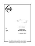
MONITOR
AUTO
BYPASS
1
2
ALARM
3
4
ON
5
6
7
8
DWELL
OFF
VS5008
SEQUEN
TIAL VID
EO SW
ITC
HER
VS5008 Series
Sequential Switcher
Installation/
Operation Manual
C809M-E (12/99)
UL
®
LISTED
Pelco • 300 W. Pontiac Way, Clovis • CA 93612-5699 USA • Pelco Online @ http://www.pelco.com
In North America and Canada: Tel (800) 289-9100 or FAX (800) 289-9150 • DataFAX (800) 289-9108
International Customers: Tel +1 (559) 292-1981 or FAX +1 (559) 348-1120 • DataFAX +1 (559) 292-0435
IMPORTANT SAFEGUARDS AND WARNINGS
Prior to installation and use of this product, the following WARNINGS should be observed.
1.
Installation and servicing should only be done by qualified service personnel and conform to all local codes.
2.
Unless the unit is specifically marked as a NEMA Type 3, 3R, 3S, 4, 4X ,6 or 6P enclosure, it is designed for indoor use only and it must not be installed where exposed to
rain and moisture.
3.
Only use replacement parts recommended by Pelco.
4.
After replacement/repair of this unit’s electrical components, conduct a resistance
measurement between line and exposed parts to verify the exposed parts have not
been connected to line circuitry.
The product and/or manual may bear the following marks:
This symbol indicates that dangerous voltage constituting a risk of electric shock is
present within this unit.
CAUTION:
RISK OF ELECTRIC SHOCK.
DO NOT OPEN.
This symbol indicates that there are important operating and maintenance instructions
in the literature accompanying this unit.
Please thoroughly familiarize yourself with the information in this manual prior to installation
and operation.
DESCRIPTION
The VS5008 is a sequential switcher designed to switch up to eight cameras manually or
automatically to one or two monitors and to respond automatically to alarm inputs.
MODELS
VS5008
Sequential switcher, eight camera inputs, two monitor outputs,
Coaxitron® compatible, desktop or rack mount, 120 VAC (UL)
VS5008/220
Same as VS5008 except 230 VAC (CE)
INSTALLATION
1.
The VS5008 Series Sequential Switcher is shipped as a terminating unit, but can be
modified for looping operation. To install the VS5008 do the following:
a.
Terminating Operation – Proceed to step 2.
b.
Looping Operation – To convert to looping operation, remove the cover. Remove
the rear panel of the chassis. Locate the 75-ohm resistors at the rear of the BNC
jacks. Use wire cutters to clip one of the resistor leads for each input that you
want to loop (refer to Figure 1). Replace the cover. Looping and terminating inputs may be mixed.
75 OHM RESISTOR
CLIP
HERE
BNC
CONNECTOR
Figure 1. Looping Conversion Modification
2
Pelco Manual C809M-E (12/99)
NOTE: MON 1 output must
be terminated at all times
with a monitor, or if not
used, by a 75-ohm BNC
terminator.
2.
Place the switcher on a desktop or install it in an equipment rack.
3.
Make alarm connections.
a.
Input Connections – The VS5008 has eight alarm inputs that require a
ground to activate. Refer to Figure 2 for connections.
b.
Output Connections – The VS5008 can activate an external device, such as
a VCR, during an alarm response. Refer to Figure 2 for connections. The output
load must not exceed 40 mA. Typical connections to this output would be active
low logic input devices, solid-state relays, or optical couplers.
4.
Make all equipment connections to the VS5008. If the system configuration utilizes
only one monitor, the monitor must be connected to the MON 2 output to allow sequencing or to display an individual channel. Refer to Figures 3 through 6 for system
configurations. If you are using the VS5008 with a Coaxitron transmitter (model
MPT9000CZ or MPT9000PZ), follow the configuration shown in Figure 7.
5.
Set all channel switches to AUTO (center). If a video input is not connected, set the
corresponding channel switch to the BYPASS (down) position.
6.
Connect the AC adapter to the 12 VAC input socket on the switcher. Connect the transformer to a 120 or 230 VAC power supply. The switcher starts sequencing.
7.
Use a screwdriver to adjust the DWELL interval control to the desired switching interval, 1 to 70 seconds nominal. Rotate the DWELL control clockwise for longer intervals
and counterclockwise for shorter intervals. This control is a 15-turn precision potentiometer. The approximate ratio is one full turn per 4 to 5 seconds of delay.
UP TO EIGHT ALARM INPUTS (ALARM
INPUT FROM MOTION DETECTOR,
DOOR CONTACT, ETC., THROUGH
NORMALLY OPEN SWITCH). EACH
ALARM DEVICE MUST BE CONNECTED
TO THE “COM” TERMINAL.
ALARM
INPUT
12 VAC
CAMERAS
COM
8
INPUT
1
2
3
4
5
UP TO EIGHT VIDEO
INPUTS
6
7
8
7
6
5
4
MON 1
3
2
1
MON 2
MON X
ALARM OUT
VS5008 (REAR)
VCR
OPEN COLLECTOR
OUTPUT FOR VCR
ACTIVATION IN
ALARM CONDITION.
ONLY ONE VCR
CAN BE USED IN
THIS CONFIGURATION
Figure 2. Alarm Hook-up
Pelco Manual C809M-E (12/99)
3
NOTE: MON 1 must be
terminated.
ALARM
INPUT
12 VAC
CAMERAS
COM
8
INPUT
1
2
3
4
5
6
7
8
7
6
5
4
MON 1
3
2
1
MON 2
MON X
ALARM OUT
VS5008 (REAR)
Figure 3. Terminating Configuration–One Monitor
NOTE: In this configuration, MON 1 must be
terminated and the unit must
be modified in order to be
looping (refer to Figure 1).
ALARM
INPUT
12 VAC
CAMERAS
COM
8
INPUT
1
2
3
4
5
6
7
8
7
6
5
4
MON 1
3
2
1
MON 2
MON X
ALARM OUT
VS5008 (REAR)
VIDEO INPUTS
ADDITIONAL EQUIPMENT
TERMINATED
Figure 4. Looping Configuration–One Monitor
4
Pelco Manual C809M-E (12/99)
ALARM
INPUT
12 VAC
CAMERAS
COM
8
INPUT
1
2
3
4
5
6
7
8
7
6
5
4
MON 1
3
2
1
MON 2
MON X
ALARM OUT
VS5008 (REAR)
Figure 5. Terminating Configuration–Two Monitors
NOTE: In this configuration
the unit must be modified in
order to be looping (refer to
Figure 1).
ALARM
INPUT
12 VAC
CAMERAS
COM
8
INPUT
1
2
3
4
5
6
7
8
7
6
5
4
MON 1
3
2
1
MON 2
MON X
ALARM OUT
VS5008 (REAR)
VIDEO INPUTS
ADDITIONAL EQUIPMENT
TERMINATED
Figure 6. Looping Configuration–Two Monitors
Pelco Manual C809M-E (12/99)
5
COAXITRON
RECEIVER
UP TO EIGHT RECEIVERS
ALARM
INPUT
12 VAC
CAMERAS
COM
8
INPUT
1
2
3
4
5
6
7
8
7
6
5
4
MON 1
3
2
1
MON 2
MON X
ALARM OUT
VS5008 (REAR)
LOOPING INPUT FROM OUTPUT TO
OUTPUT
RECEIVER
MONITOR
J8
J7
J6
COAXITRON®
TRANSMITTER
(REAR)
NOTE: IN THIS CONFIGURATION, THE LOOPING OUTPUT (J8) IS UNTERMINATED
Figure 7. VS5008 with a Coaxitron Transmitter
OPERATION
ONE-MONITOR OPERATION
When the VS5008 is configured for one-monitor operation, the monitor must be connected
to the MON 2 output. The eight video inputs will automatically sequence through the monitor. To remove a channel from the sequence, set the channel’s switch to BYPASS. Switching
any channel to the MONITOR position will interrupt the sequence and display input from the
selected channel onto the monitor.
TWO-MONITOR OPERATION
When configured for two-monitor operation, the eight video inputs will automatically sequence through Monitor 1. To remove a channel from the sequence, set the channel’s switch
to BYPASS. To view a single channel, set the channel’s switch to the MONITOR position.
Monitor 2 displays the output. Monitor 2’s output will not interfere with Monitor 1’s sequencing. If all switches are set to the AUTO position, Monitor 2 sequences with Monitor 1. If more
than one channel switch is set to the MONITOR position, the lowest number switch takes
precedence.
ALARM OPERATION
Set the ALARM switch to the ON position.
If all the channel switches on the front panel are set to AUTO when an alarm occurs, both
monitors immediately switch to the alarmed channel and the associated LED blinks. If more
than one alarm is triggered, the monitors sequence simultaneously, at a three-second rate,
between the alarmed channels.
6
Pelco Manual C809M-E (12/99)
If a channel is set to the MONITOR position, Monitor 1 switches to the alarmed channel but
Monitor 2 continues to display the selected channel. If a channel is set to BYPASS, Monitor
1 switches to the alarmed channel.
Once an alarm is triggered, the alarm remains on until the alarm condition is removed or
the alarm switch is moved to the OFF position.
When the alarm switch is in the OFF position, the switcher ignores any alarm inputs.
SERVICE MANUAL
If you need to service your unit, obtain a service manual in one of the following ways:
•
•
•
Go to Pelco’s web site at ftp://www.pelco.com and find service manual C809SM.
Call Pelco’s DataFAX service at 1-800-289-9108 or 1-559-292-0435 and request document 28098.
Contact Pelco’s Literature Department and request service manual C809SM.
SPECIFICATIONS
VIDEO
Inputs:
Outputs
Monitor 1/2:
Monitor X:
Gain:
Dwell:
Frequency
Response:
Maximum
Signal Level:
Tilt:
Crosstalk:
Terminating (75 ohms) or looping
75 ohms
Coaxitron transmitter (non-amplified) output
Unity
Adjustable from 1-70 seconds nominal
Flat within ±1 dB to 10 MHz
2 Vp-p
< 2%
Better than -40 dB at 5.5 MHz
ELECTRICAL
Power Requirements
for Transformer:
1.5 vA (.125 amp) at 12 volts RMS ±15% 50/60 Hz from a dedicated,
isolated power supply. Wall transformer provided with unit, 120 or 230
VAC operation
Connectors:
BNC
Alarm In:
Normally open relay contact, 10V at 1 mA
Alarm Out:
Open collector
GENERAL
Construction
Chassis:
Cover:
Panel:
Environment:
Dimensions:
Weight:
RATINGS:
Steel, zinc plated
Steel, black polyester powder coat
Aluminum, black polyester powder coat with white silk screen
32° to 120°F (0° to 49°C)
1.75 (H) x 14.50 (W) x 8.50 (D) inches (4.45 x 36.83 x 21.59 cm)
7 lb (3.17 kg)
NEMA 1
(Design and product specifications subject to change without notice.)
Pelco Manual C809M-E (12/99)
7
REGULATORY NOTICES
This equipment has been tested and found to comply with the limits of a Class B digital device, pursuant to part 15 of the FCC rules. These limits are designed to provide reasonable
protection against harmful interference in a residential installation. This equipment generates, uses, and can radiate radio frequency energy and, if not installed and used in accordance with the instructions, may cause harmful interference to radio communications. However there is no guarantee that the interference will not occur in a particular installation. If
this equipment does cause harmful interference to radio or television reception, which can
be determined by turning the equipment off and on, the user is encouraged to try and correct the interference by one or more of the following measures:
•
Reorient or relocate the receiving antenna.
•
Increase the separation between the equipment and the receiver.
•
Connect the equipment into an outlet on a circuit different from that to which the receiver is connected.
•
Consult the dealer or an experienced radio/TV technician for help.
WARRANTY AND RETURN INFORMATION
WARRANTY
Pelco will repair or replace, without charge, any merchandise proved defective in material or workmanship for a period of one year after the date of
shipment. Exceptions to this warranty are as noted below:
•
•
•
•
•
•
Three years on Genex® Series (multiplexers, server, and keyboard).
Two years on all standard motorized and fixed focal length lenses.
Two years on Esprit™, Legacy®, Intercept®, PV1000 Series, CM6700/
CM8500/CM9500/CM9750/CM9760 Matrix, Spectra®, DF5 Series and DF8
Fixed Dome products.
Two years on WW5700 series window wiper (excluding wiper blades).
Two years on cameras.
Six months on all pan and tilts, scanners or preset lenses used in continuous
motion applications (that is, preset scan, tour and auto scan modes).
Pelco will warrant all replacement parts and repairs for 90 days from the date
of Pelco shipment. All goods requiring warranty repair shall be sent freight
prepaid to Pelco, Clovis, California. Repairs made necessary by reason of
misuse, alteration, normal wear, or accident are not covered under this warranty.
Pelco assumes no risk and shall be subject to no liability for damages or loss
resulting from the specific use or application made of the Products. Pelco’s
liability for any claim, whether based on breach of contract, negligence, infringement of any rights of any party or product liability, relating to the Products shall not exceed the price paid by the Dealer to Pelco for such Products.
In no event will Pelco be liable for any special, incidental or consequential
damages (including loss of use, loss of profit and claims of third parties) however caused, whether by the negligence of Pelco or otherwise.
If a warranty repair is required, the Dealer must contact Pelco at (800) 2899100 or (559) 292-1981 to obtain a Repair Authorization number (RA), and
provide the following information:
1. Model and serial number
2. Date of shipment, P.O. number, Sales Order number, or Pelco invoice number
3. Details of the defect or problem
If there is a dispute regarding the warranty of a product which does not fall
under the warranty conditions stated above, please include a written explanation with the product when returned.
Ship freight prepaid to:
Method of return shipment shall be the same or equal to the method by which
the item was received by Pelco.
RETURNS
In order to expedite parts returned to the factory for repair or credit, please
call the factory at (800) 289-9100 or (559) 292-1981 to obtain an authorization number (CA number if returned for credit, and RA number if returned for
repair). Goods returned for repair or credit should be clearly identified with
the assigned CA/RA number and freight should be prepaid. All merchandise
returned for credit may be subject to a 20% restocking and refurbishing charge.
Ship freight prepaid to:
The above warranty provides the Dealer with specific legal rights. The Dealer may
also have additional rights, which are subject to variation from state to state.
Pelco
300 West Pontiac Way
Clovis, CA 93612-5699
Pelco
300 West Pontiac Way
Clovis, CA 93612-5699
REVISION HISTORY
Manual #
C809M
C809M-E
Date
9/92
12/99
Comments
Rev D.
Moved exploded assembly diagram, parts list, and schematic to new maintenance/service manual (C809SM). Updated
manual to new format.
® Pelco, the Pelco logo, Spectra, Genex, Legacy, Coaxitron, and Intercept are registered trademarks of Pelco.
™ Esprit is a trademark of Pelco.
8
© Copyright 1999, Pelco.
All rights reserved.
Pelco Manual C809M-E (12/99)