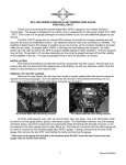
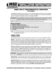
1
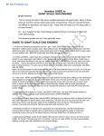
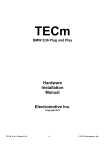
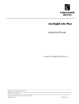
MCL-3000 SERIES OUTSIDE AIR TEMPERATURE
PART# MCL-3K-T
Thank you for purchasing the Dakota Digital MCL-3K-T gauge for your Harley Davidson Touring bike.
This gauge is designed to be a direct, plug in replacement for all touring models from 1996 and up. This
is part of a six gauge package for touring models so you can add additional gauges as you choose.
The MCL-3K-T gauge comes with a temperature sensor. You must use the supplied sensor,
other sensors will result in inaccurate readings.
INSTALLATION
First read and familiarize yourself with all of the components and this manual. The first step is to
remove the seat and disconnect the negative side of the battery, as with any electronic install. Once the
battery is disconnected you are ready to start.
REMOVAL OF FACTORY GAUGES
Remove the outer fairing; this will vary from model to model, please follow the service manual to
expose the wiring and gauges. Don’t be alarmed by the amount of wires behind the fairing, this is a
direct plug in kit and these detailed instructions will guide you through it.
Pic of Street Glide with outer fairing removed
Pic of Road Glide with outer fairing removed
All of the small gauges, fuel, volts, oil, and air temp have two plugs. One is for illumination the
other is for the gauge power, ground, and sensor signal. The illumination harness, two pins (orange and
black wires), will not be reused and can hang freely inside the fairing with the bulb removed, or can be
secured to the other gauge wires to clean things up. The three pin connector from the stock gauge will be
used to connect the new Dakota Digital MCL-3K gauge. Unplug connectors at the back of the gauge,
then remove the two 5/16” nuts holding the clamps onto each small gauge and remove the gauges.
***New nuts for the small gauges are included in the hardware pack DO NOT reuse the stock nuts for the
new gauges; they are not the same thread.
Manual # 650302:B
Once the gauge is removed, save the clamp as it will be reused with the new MCL gauge.
Remove the small gauge with 5/16” wrench or nut driver
Save Clamp, and reuse for install
INSTALLATION OF NEW MCL-3K-T GAUGE
Install the new gauge into the fairing using the original clamp, along with the supplied nuts. Be
sure the alignment tab on the clamp lines up with the notches in the fairing when tightening the clamp
back up, flat side down.
SWITCH/DIM
PLUG
SENDER
POWER
(+12V Key ON)
GROUND
WIRING
Wiring the gauge will be slightly different than before as the bike doesn’t have provisions for the
new sensor. Use the supplied sensor and wiring to make a jumper harness from the original plug to the
new BOOST gauge.
*DO NOT connect the factory connector direct to the gauge, use supplied wiring.
If the wiring harness plug is not available, wire according to the drawing on next page. Standard
¼” female spade connectors can be used to make a connection to the gauge.
The second connector toward the top of the back side of the gauge is where the supplied
Switch/Dim harness connects. Both inputs are “triggered” when there is +12V on either wire.
BLUE Wire (Dim Input)
The BLUE wire is used for optional night time dimming function. When this wire receives
+12V the gauge will dim to about ½ brightness.
GREEN Wire (Switch Input)
The GREEN wire is used for a switch input for entering setup. This wire can be wired to a
momentary push button switch and the other side of the switch to +12V. The wire can
also be stripped back and touched to +12V to enter setup and then taped off once
complete.
(Wiring diagram on next page)
Manual # 650302:B
Dim and
Switch
+12V power
RED (PWR)
Temp sensor
Signal
RED (SND)
Ground
BLACK (GND)
Temp sensor
Ground
BLACK (GND)
Factory
gauge plug
Back View of Gauge
Switch Input (active high +12V)
GREEN wire
Dim Input (active high +12V)
BLUE wire
+12V
+12V
KEY ON POWER
Optional toggle
switch
Optional momentary
push button switch
+12V
KEY ON POWER
RED wire
Sender Terminal
KEY ON POWER
BLACK wire
TEMP SENSOR
(supplied)
Connect to main
chassis ground
If you are replacing a gauge in a set of Dakota Digital gauges, plug the small, white, two-pin
connector into the air pressure gauge just as it was on the other gauge you removed. If you are adding
this gauge to the set rather than replacing one (you will have a total of 5 small Dakota Digital gauges on
the bike) you will need to locate any one of the other BLUE and GREEN wires going to the other gauges
in the set, cut and splice into the new harness. Match BLUE to BLUE and GREEN to GREEN. If you are
installing multiple MCL-3K gauges without a Dakota Digital Speedometer, you can tie the GREEN wires
together and then to one switch. The same is true for the BLUE wire, wire all of them to one switch.
If you have an MCL-3K Tachometer, it will actually serve as the dimming “switch”. The BLUE
wire on any of the MCL-3K Tachs will provide a +12V output for the dimming function. The gauge has a
light sensor behind the lens and when the ambient light is dim or low it will “turn on” the output and
supply +12V to the BLUE wire. You will not need to wire in a toggle switch if you have an MCL-3K
tachometer and choose to wire it this way.
Back View of Gauges
Dim Input (+12V)
BLUE wire
+12V
KEY ON POWER
Switch Input (+12V)
GREEN wire
+12V
KEY ON POWER
Optional toggle
switch
Continue wiring to other
MCL-3K gauges
Optional momentary
push button switch
Manual # 650302:B
To complete the installation, run the sensor cable/wire down and out the bottom of the fairing, securing it
as needed with the supplied zip ties. It is best to mount the sensor so it will get some air flow, securing it
to a brake line or bracket just out the bottom of the fairing works well.
Zip
Zip tie
tie
Sensor
Brake line
Manual # 650302:B
GAUGE SETUP
The GREEN switch input wire, in the two pin connector, is used to enter setup. If you are only
installing one or a couple Dakota Digital MCL-3K gauges set up may seem a little strange since they are
designed to work as a set, however you’ll simply cycle through a few screens to get to the desired gauge.
The table below shows what will be on the gauge with each button press, or tapping the GREEN wire
high +12V.
Speed
Tach
Oil psi Oil temp
Fuel
Volt
Air Temp
1st
- 1 -
CL
- 1 -
- 1 -
- 1 -
- 1 -
- 1 -
2
SPd
- 2 -
- 2 -
- 2 -
- 2 -
- 2 -
- 2 -
3rd
- 3 -
tCH
- 3 -
- 3 -
- 3 -
- 3 -
- 3 -
4th
- 4 -
- 4 -
PSI
- 4 -
- 4 -
- 4 -
- 4 -
5th
- 5 -
- 5 -
- 5 -
F or C
- 5 -
- 5 -
- 5 -
6th
- 6 -
- 6 -
- 6 -
- 6 -
FUL
- 6 -
- 6 -
7
- 7 -
- 7 -
- 7 -
- 7 -
- 7 -
uLt
- 7 -
8th
- 8 -
- 8 -
- 8 -
- 8 -
- 8 -
- 8 -
AIR
nd
th
Please note that the word “switch” in the setup instruction is in reference to the GREEN wire, you
can install any momentary push button switch and use that or simply strip the wire back and hold or tap
the GREEN wire to a +12V source for set up. Once setup is complete, cover the end of the GREEN wire
and secure it so it cannot accidentally be shorted.
To enter setup:
•
•
•
•
•
•
Press and hold the switch while turning the key on, the gauge should light and show “dxx” (xx is
the software code and may be used for tech support).
Release the switch and “-1-” should be displayed. Looking at the table, above, press and
release the switch and scroll through until you see “AIR” on the display; this is the screen you
need to get to in order to enter the air temperaure setup.
Press and hold the switch until “vnt” is displayed, release the switch and the current temperature
unit will be displayed.
Press and release the switch to change between Fahrenheit “F
F” and Celsius “C”.
When the desired unit is displayed, press and hold the switch until “---” is displayed to save
changes.
Turn off key. Setup is complete.
Manual # 650302:B
Troubleshooting guide
Problem
Gauge will not light up.
Gauge reading is erratic or
jumps around.
Gauge reading is incorrect.
Gauge will not dim.
Gauge remains dim at all
times.
Gauge will not enter setup.
Possible cause
Orange wire does not have power.
Black wire is not getting a good ground.
Gauge is damaged.
Gauge signal wire is loose or broken.
Poor ground connection.
Sensor is damaged.
Blue wire (2-pin harness) is not connected
correctly.
Blue wire (2-wire harness) is getting power all
all of the time.
Green wire (2-wire harness) is not connected
correctly.
Solution
Connect to a location that has power, check fuses.
Connect ground to a different location.
Return gauge for repair. (see instructions)
Check all wire connections and inspect wire for breaks.
Check ground connection on gauge, engine, and sensor.
Verify wiring or replace sensor.
Check wiring connections. Blue wire should have 12 volts
when tachometer is dim or dimming switch is on.
Check wiring connections. Blue wire should have 0 volts
when tachometer is bright or dimming switch is off.
Check wiring connections. Green wire should have 12 volts
when the switch is pressed.
SERVICE AND REPAIR
DAKOTA DIGITAL offers complete service and repair of its product line. In addition, technical consultation is available to help you work through any
questions or problems you may be having installing one of our products. Please read through the Troubleshooting Guide. There, you will find the solution to most
problems.
Should you ever need to send the unit back for repairs, please call our technical support line, (605) 332-6513, to request a Return Merchandise
Authorization number. Package the product in a good quality box along with plenty of packing material. Ship the product by UPS or insured Parcel Post. Be sure
to include the RMA number on the package, and include a complete description of the problem with RMA number, your full name and address (street address
preferred), and a telephone number where you can be reached during the day. Any returns for warranty work must include a copy of the dated sales receipt from
your place of purchase. Send no money. We will bill you after repair.
Dakota Digital 24 Month Warranty
DAKOTA DIGITAL warrants to the ORIGINAL PURCHASER of this product that should it, under normal use and condition, be proven defective in
material or workmanship within 24 MONTHS FROM THE DATE OF PURCHASE, such defect(s) will be repaired or replaced at Dakota Digital’s option.
This warranty does not cover nor extend to damage to the vehicle’s systems, and does not cover removal or reinstallation of the product. This Warranty
does not apply to any product or part thereof which in the opinion of the Company has been damaged through alteration, improper installation, mishandling, misuse,
neglect, or accident.
This Warranty is in lieu of all other expressed warranties or liabilities. Any implied warranties, including any implied warranty of merchantability, shall be
limited to the duration of this written warranty. Any action for breach of any warranty hereunder, including any implied warranty of merchantability, must be brought
within a period of 24 months from date of original purchase. No person or representative is authorized to assume, for Dakota Digital, any liability other than
expressed herein in connection with the sale of this product.
Manual # 650302:B