1
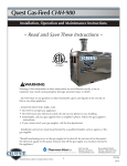
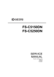
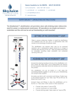
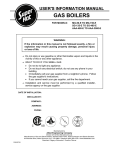
INSTALLATION AND SERVICE MANUAL
EPP SERIES – INDIRECT WATER HEATERS
FOR MODELS EPP-40 TO EPP-120
SEE REAR COVER FOR INDEX
Read this instruction manual before installation, operation, or service. Failure to follow
the instructions in this manual may result in severe personal injury, death or substantial
property damage. Installation and service must be performed by a qualified service
technician.
Manufactured by
Allied Engineering Company
Division of E-Z-Rect Manufacturing Ltd.
Manufacturers of Gas and Electric Boilers, Stainless Steel Tanks, Heat Exchangers and Electric Boosters
94 Riverside Drive, North Vancouver, B.C. V7H 2M6 • Telephone (604) 929-1214 • FAX (604) 929-5184
Branches: Calgary • Edmonton • Toronto
PN5242745
Price $5
EPP SERIES INDIRECT WATER HEATERS – Installation and Service Manual
DIMENSIONS AND SPECIFICATIONS
Storage Sizes (Nominal)
EPP-40-SC
40 US Gal.
EPP-60-SC
60 US Gal.
EPP-60-SCR
60 US Gal.
EPP-60-DC
60 US Gal.
EPP-80-SC
80 US Gal.
EPP-80-DC
80 US Gal.
EPP-120-SC
120 US Gal.
EPP-120-DC
120 US Gal.
SC = Single Coil
DC = Double Coil
SCR = Crawl Space Design (Single Coil)
Features
Quality Construction
• Fast Recovery Time
• 316L Stainless Steel Tank
• Highest Heat Transfer Efficiency
• 316L Stainless Steel Heat Exchanger
• Low Standby Heat Loss
• Aquastat and Stainless Steel Thermowell
• Easy Installation
• Magnesium Anode
• Warranty: 10 Year for Residential.
• Passivated for additional Corrosion Protection
See warranty for details.
Note:
Single Coil heat exchanger uses 1” O.D. x 30 ft long Stainless Steel tube.
Maximum Operating Pressure: 150 psi
Maximum Tank Temperature: 150°F
Maximum Coil Temperature: 210°F
Recovery
(Based on Boiler Flow Rate of 10 GPM)
Inlet From
Boiler
Temp.°°F
1st 10 Min.
Delivery
@ 135 °F
US Gal.
1st Hour
Delivery
@ 135 °F
US Gal.
Continuous
Delivery
@115 °F
US GPH
Thermal Input
Requirements
Btu/Hr
EPP-40-SC
200
190
180
66
63
60
194
176
159
226
205
184
129,000
117,000
105,000
EPP-60-SC
200
190
180
86
83
80
214
196
179
226
205
184
129,000
117,000
105,000
EPP-60-SCR
200
190
180
86
83
80
214
196
179
226
205
184
129,000
117,000
105,000
EPP-60-DC
200
190
180
102
97
92
313
284
253
383
346
309
219,000
198,000
176,000
EPP-80-SC
200
190
180
105
102
100
232
215
198
226
205
184
129,000
117,000
105,000
EPP-80-DC
200
190
180
122
117
112
333
304
273
383
346
309
219,000
198,000
176,000
EPP-120-SC
200
190
180
146
143
140
274
256
239
226
205
184
129,000
117,000
105,000
EPP-120-DC
200
190
180
163
157
152
375
345
314
383
346
309
219,000
198,000
176,000
Model Number
Dimensions
Fitting Sizes
E
F
G
H
I
J
EPP-40-SC
EPP-60-SC
EPP-60-SCR*
EPP-60-DC
21”
21”
27”
21”
7 5/8”
7 5/8”
10 13/16”
7 5/8”
24 1/8”
24 1/8”
27 5/16”
24 1/8”
42 5/16”
60 5/16”
36 3/8”
60 5/16”
30 1/8”
46 5/8”
EPP-80-SC
EPP-80-DC
EPP-120-SC
EPP-120-DC
23”
23”
27”
27”
10 1/4”
10 1/4”
10 11/16”
10 11/16”
26 3/4”
26 3/4”
27 3/16”
27 3/16”
63 5/16”
63 5/16”
64 5/8”
64 5/8”
32 7/8”
33 3/16”
49 1/4”
49 11/16”
Weight
A
B
C
Hot Water
Cold
Inlet from
Outlet
Water Inlet
Boiler
¾”
¾”
¾”
¾”
1”
1”
1 ½”
1 ½”
¾”
¾”
¾”
¾”
1”
1”
1 ½”
1 ½”
D
Outlet to
Boiler
1”
1”
1”
1”
1”
1”
1”
1”
* Anode for EPP-60-SCR located at bottom of tank instead of top.
Also available:
• “Stacker” Indirect Fired Hot Water Tank in 40 US gallon – boiler can be stacked on casing to save floor space
• EPP Storage Tanks in 40, 60, 80, and 120 US gallon
The Super Hot product improvement program may result in changes to design and/or specifications being made without notice.
2
1”
1”
1”
1”
1”
1”
1”
1”
144 LB
182 LB
164 LB
196 LB
198 LB
212 LB
236 LB
256 LB
EPP SERIES INDIRECT WATER HEATERS – Installation and Service Manual
1.0
PRE-INSTALLATION
1.1
RECEIVING
INSPECT SHIPMENT FOR POSSIBLE DAMAGE. All goods are carefully manufactured, inspected,
checked and packed by experienced workers. The manufacturer's responsibility ceases upon delivery of
goods to the carrier in good condition. Any claims for damage and/or shortage in shipment or non-delivery
must be filed immediately against the carrier by the consignee.
Use care when receiving and unpacking the tank. Dropping the tank may cause damage and prevent safe
and proper operation.
1.2
INSTALLATION CODES AND REQUIREMENTS
All applicable national, provincial/state, and local codes, laws, regulations, and ordinances must be
followed. They expand on and take precedence over any recommendations in this booklet. Authorities
having jurisdiction shall be consulted before installations are made.
If an external electrical source is utilized, the hot water tank, when installed, must be electrically grounded
in accordance with local codes or, in the absence of local codes, with the National Electrical Code,
ANSI/NFPA 70 (current edition) and/or the Canadian Electrical Code, CSA C22.1 Part 1 (current edition).
If there is any conflict in the above requirements, the more stringent requirement applies.
The installation and service must also conform to the additional requirements in this manual. If there is
any conflict with a requirement in this manual and a code requirement, the code requirement must be
followed.
1.3
LOCATION
•
•
•
•
•
•
•
•
This tank should not be placed where freezing might occur and is not to be installed outdoors.
This tank is designed for vertical installation. Install the tank on an area that is stable, flat, level
and capable of supporting the weight of the tank when filled with water. CAUTION: Failure to
support and stabilize the water heater could result in severe personal injury, death or substantial
water damage.
Although minimal clearance is required for this tank, ensure that there is sufficient room for the
water heater to access all of the fittings easily. We recommend a service clearance of 24”
around plumbing connections.
CAUTION: The tank should be located in an area where leakage of the indirect water heater or
connections will not result in damage to the area adjacent to the appliance or to lower floors of the
structure. When such locations cannot be avoided, it is recommended that a suitable drain pan,
adequately drained (connected to a drain), be installed under the tank.
This tank must be installed such that any electronic components are protected from water
(dripping, spraying, rain, etc.) during appliance operation and service.
Avoid heat loss and friction loss by locating the tank as close to the boiler as possible. Further
heat loss should be avoided by insulating the pipe.
For the fastest delivery of hot water, locate the water heater in a position central to the points of
use.
DANGER - Risk of Explosion: Do not use or store gasoline or other flammable fuels or
chemicals which have flammable vapors near the tank. The vapors may be ignited by the heat or
electronic components of the tank.
3
EPP SERIES INDIRECT WATER HEATERS – Installation and Service Manual
1.4
OPERATING RESTRICTIONS
CAUTION: Single wall heat exchangers must use a heat transfer medium such as water or other nontoxic fluids having a toxicity rating of Class 1, as listed in Clinical Toxicology of Commercial Products
(current edition). The pressure of the heat transfer medium must be limited to a maximum of 150psi by an
approved pressure relief valve.
Maximum working pressure of the tank is 150psi.
1.5
WATER QUALITY
Always use good quality water to prolong the life of the tank. Water that is safe to drink and even city
water is not necessarily good quality water for the tank. The use of filters can prevent corrosion and
reduce sediments inside the tank. Water hardness, pH, and chlorides must be controlled to normal levels.
•
PH levels must be between 6.0 and 8.0 and dissolved chlorides below 100ppm.
If you are unsure, use a water softening system or consult a qualified water treatment expert.
NOTE: All improper use as detailed above could void the warranty of the tank.
4
EPP SERIES INDIRECT WATER HEATERS – Installation and Service Manual
2.0
PIPING AND PLUMBING
2.1
BOILER SIDE PLUMBING
Connect boiler out (hot) supply piping to the fitting marked “boiler in” on the water tank. The “boiler out”
fitting on the tank should be piped to the boiler return. Use Teflon tape, pipe dope, or both on all threaded
fittings. When installing the pump make sure that the direction arrow is pointing in the same direction as
the flow. The use of shut off valves and dielectric unions are recommended when installing your water
tank to simplify future service requirements.
To prevent a back flow through the water heater when heating a radiant system, a check valve or back
flow preventer must be installed.
The heat output of the tank is based on the temperature and flow rate from the boiler supply. To ensure
that the minimum flow rate is provided, use at least 1 inch pipe size (from boiler to tank) and a zone valve
with a minimum 1 inch diameter and flow coefficient of at least CV = 8.
Hot Water Priority
A boiler system connected to multiple zones may be installed so that domestic water heating will be given
priority over other zone heating. If hot water priority is used, preventative measures must be taken to
ensure hot water priority during cold weather conditions does not result in freezing damage to the other
zones.
Sample Systems
Although there are unlimited possibilities for your indirect water heater system, some typical installations
are described and shown below. Note that all heating zones can be controlled either by using circulators
(pumps) or zone valves as long as correct flow is provided.
Dedicated Single Boiler with Single Coil Tank
Radiant Floor / Baseboard with 3 Port Zone Valve – Domestic Priority
Radiant Floor / Baseboard with 2 Port Zone Valve – Domestic Priority
Radiant Floor / Baseboard Using Circulator and Domestic Hot Water Priority
Dedicated Single Boiler with Double Coil Tank
Radiant Floor or Hot Tub / Pool Using Double Coil Tank
Multiple Water Heaters – Domestic Priority
Multiple Water Heaters Piped in Series
Standard Circulators Zone:
Run the same as a standard heating zone except one zone is piped to the water heater and can be
prioritized by correct use of the control valve. Ensure that the circulator is sized correctly to allow the boiler
water to flow at the correct rate.
Zone Valve System:
Run the same as a standard heating zone except one zone is piped to the water heater and can be
prioritized with correct use of the zone valves. Ensure that the circulator is sized correctly to allow the
boiler water to flow at the correct rate. Do not use a zone valve less than 1 inch diameter and CV = 8.
3-way Zone Valve System:
For prioritizing your water heater, a 3-way zone valve can be installed into your system. This system
overrides all other “calls for heat” when there is a demand from the water heater aquastat. All the boiler
water is then diverted to the water heater. There are three ports on a 3-way valve: a common port, a
normally closed port, and a normally open port. The common port is connected to the boiler side; the
normally open port connected to the heating zone and the normally closed is connected to the water
heater coil. The boiler water flows through the heating zone, until the water heater aquastat demands
more heat. The zone valve is then activated and the boiler water is diverted to the water heater; once the
requested water temperature is achieved the aquastat will shut off power to the zone valve and the boiler
water will be diverted back to the heating zone.
5
EPP SERIES INDIRECT WATER HEATERS – Installation and Service Manual
2.2
INSTALLATION DIAGRAMS
Sample Schematics Boiler Side Piping
6
EPP SERIES INDIRECT WATER HEATERS – Installation and Service Manual
7
EPP SERIES INDIRECT WATER HEATERS – Installation and Service Manual
Double Coil for larger hot water demand
8
EPP SERIES INDIRECT WATER HEATERS – Installation and Service Manual
Multiple Water Heaters
9
EPP SERIES INDIRECT WATER HEATERS – Installation and Service Manual
2.3
DOMESTIC SIDE PLUMBING
Connect domestic water in and domestic water out to the marked fittings on the water heater. Use Teflon
tape, pipe dope, or both on all threaded fittings. Connect drain valve near the inlet connection so that the
tank can be drained. Shut off valves and dielectric unions must be used when installing your water tank to
simplify future service requirements and prevent galvanic corrosion.
You must install an expansion tank of adequate capacity if a backflow preventer, check valve, or pressurereducing valve is installed on the cold-water inlet. Do not install any valve or restrictions between
expansion tank and hot water tank inlet. Improper piping of the expansion tank or backflow preventer can
cause excessive pressure in the water heater, which can cause severe personal injury, death or
substantial damage to property.
Actual service pressure should not exceed that of pressure stamped on the T & P relief valve minus 25psi.
2.4
T&P RELIEF VALVE PLUMBING
Install the T&P relief valve directly into the ¾” tapping located near the top of the tank so that the
temperature sensing element is immersed in the water within the top 6 inches of the tank. No valve,
reducing coupling or other restriction is to be placed between the relief valve and the tank connection. No
valve, reducing coupling, pipe plug, pipe cap or other restriction is to be placed in the discharge piping.
Improper placement or piping of the T&P relief valve can cause severe personal injury, death or
substantial property damage.
The discharge line shall be installed to allow the complete drainage of both the valve and the line. It shall
be independently supported or arranged so as to avoid undue stress on the valve. The discharge line
must be installed to allow complete drainage of both the valve and line. Do not pipe in any area where
freezing may occur.
The termination of the T&P relief valve discharge line shall be downward and not directly connected to a
sewer line. The outlet of the discharge line shall terminate in the vicinity of a point of drainage within 6” of
the floor to eliminate potential risk of scalding.
Temperature and pressure settings of the T&P relief valve are factory set and are not adjustable.
DANGER: Do not plug T&P relief valve or discharge piping. Plugging T&P relief valve or discharge piping
can cause excessive pressure in water heater, resulting in severe personal injury, death or substantial
property damage.
2.5
WATER HAMMER
Water hammer is a damaging pressure shock wave created when the flow of water is suddenly stopped or
reduced (possibly induced by fast-closing faucet, reducing valve, or solenoid valve in a clothes/dish
washing machine). This condition is commonly associated with hammering noises and vibrations;
however, lack of noise does not assure that water hammer is not present. Risers or air chambers must
not be used. To prevent damage to pipes and appliances: (1) Install water hammer arrestors at all
required locations and (2) adequately size pipes to ensure a maximum water velocity less than 5 ft/s.
10
EPP SERIES INDIRECT WATER HEATERS – Installation and Service Manual
Domestic Side Piping
Domestic piping with thermostatic mixing valve
11
EPP SERIES INDIRECT WATER HEATERS – Installation and Service Manual
3.0
WIRING DIAGRAMS
WARNING: Turn off all the electric power before any wiring or service. All circuit breakers ahead of or
related to the boiler and tank operation must be switched off.
CAUTION: Label all wires prior to disconnection when servicing controls. Wiring errors can cause
improper and dangerous operation.
When installed the tank must be grounded in accordance with local codes or, in the absence of local
codes, with the National Electrical Code ANSI/NFPA 70, and/or the CSA C22.1 Electrical Code.
All wiring is to be done in accordance with all applicable local and state/provincial codes.
Wiring for the aquastat is to be connected through the junction box below the aquastat opening. The
aquastat is to be connected in series. For line voltage connections over 30 volts, wiring must be securely
fastened at the junction box opening (not provided).
12
EPP SERIES INDIRECT WATER HEATERS – Installation and Service Manual
13
EPP SERIES INDIRECT WATER HEATERS – Installation and Service Manual
14
EPP SERIES INDIRECT WATER HEATERS – Installation and Service Manual
15
EPP SERIES INDIRECT WATER HEATERS – Installation and Service Manual
16
EPP SERIES INDIRECT WATER HEATERS – Installation and Service Manual
4.0
STARTUP AND ADJUSTMENT
DANGER: Before filling the tank, make sure that the T&P relief valve is installed and that the unit is
properly grounded.
CAUTION: Never use tank until it is filled with water and connected to the domestic water piping and
boiler piping.
4.1
4.2
PRE-START UP CHECKLIST
T&P relief valve is properly installed and drain discharge is directed away to a drain.
Domestic cold and hot water lines are correctly connected to domestic water system.
Boiler supply and return piping is correctly connected from boiler to the tank.
Domestic and boiler water systems are correctly pressurized.
All wiring is installed correctly, no exposed high voltage wiring is present and the unit is properly
grounded.
STARTUP INSTRUCTIONS
1. Make sure all electrical power is OFF.
2. Close the drain valve on tank.
3. Open domestic water supply valve.
4. Open the closest hot water faucet to vent air from the system.
5. Close faucet when there is a constant flow of water.
6. For boiler side piping, follow boiler instructions to purge air.
7. The tank, domestic water piping, and boiler water piping should be completely filled with water
and all air extracted from both domestic and boiler water systems.
8. Set aquastat on water heater. An initial setting of 120°F (49°C) is recommended. The aquastat is
adjusted to its lowest temperature setting when shipped from the factory.
9. Power up boiler (following boiler instructions) and water heater.
10. Check boiler is operating normally.
11. Check zone valve or circulator is in good condition.
12. Check all connections, fittings and piping for leaks.
13. Adjust the temperature at the faucets as described in the next section.
17
EPP SERIES INDIRECT WATER HEATERS – Installation and Service Manual
5.0
WATER ADJUSTMENT
DANGER: Water Temperatures over 125°F (52°C) can cause severe burns instantly or death from
scalds. Feel water before bathing and showering. Homes that have small children, elderly and disabled
persons may wish to lower the water heater setting to 120°F (49°C) to prevent potential scalding. Below is
a table showing the approximate time it takes to have a scalding accident for different temperatures of hot
water:
Water Temperature
Length of Time to Cause Scalding
125ºF (52ºC)
1 1/2 to 2 minutes
130ºF (54ºC)
about 30 seconds
135ºF (57ºC)
about 10 seconds
140ºF (60ºC)
less than 5 seconds
145ºF (63ºC)
less than 3 seconds
150ºF (66ºC)
about 1 1/2 seconds
Maximum boiler water temperature is 210ºF
You should install a mixing valve or tempering valve on the
domestic hot water supply and set to 120°F (49°C).
Valves for reducing point of use temperature by mixing cold and hot
water are available. Consult a licensed plumber or local plumbing
authority.
WARNING: Studies show that dangerous bacteria can form in domestic water distributions systems if a
minimum water temperature is not maintained. For example, legionella pneumophila, can form in hot water
maintained at 115°F (46°C) or lower. We recommend a domestic water temperature not lower than 122°F
(50°C) at faucets and a tank temperature not lower than 140°F (60°C) to limit the potential for legionella
pneumophila growth. Contact your local health authority for more information.
5.1
CONTROL/AQUASTAT
Insert the control into the factory installed stainless steel well and secure it to the well by using the screw
on the aquastat body. Thermal paste is recommended but not required.
The water temperature and the setting of the aquastat will be similar most of the time but due to unusual
usage patterns the outlet water temperature may rise significantly above the setting of the aquastat. To
control this fluctuating temperature, a thermostatic mixing valve (tempering valve) should be installed.
5.2
AQUASTAT TEMPERATURE
•
Use the aquastat to control the maximum water temperature in the tank. Its differential is fixed at
5ºF (3ºC). Its maximum setting is 160°F (71°C).
•
Household water usage patterns will affect water temperature at any faucet or shower. Always
check temperature at every point after adjusting aquastat.
•
When hot water is used in repeated small quantities the upper layer of water in tank can be much
hotter than lower layers. When adjusting the aquastat, be sure boiler limit control is set a minimum
20°F (11°C) higher. However, in no case should boiler limit control be set above 210°F (99°C).
18
EPP SERIES INDIRECT WATER HEATERS – Installation and Service Manual
5.3
TEMPERATURE ADJUSTMENT
Allow the water heater to operate several heat-up cycles and check the water temperature at the faucet to
verify proper operation.
•
If the water at the faucet is hotter than needed:
1. Adjust the aquastat to a lower temperature setting.
2. Draw sufficient water or allow the water to sit until another heat-up cycle is initiated.
3. Wait until the heat-up cycle is completed.
4. Recheck the water temperature at the faucet.
•
If the water at the faucet is colder than needed:
1. Adjust the aquastat to a higher temperature setting.
2. If a heat-up cycle begins, wait until the heat-up cycle is completed and recheck the water
temperature at the faucet.
3. If a heat-up does not begin, draw sufficient water or allow the water to sit until a heat-up
cycle is initiated. Wait until the heat-up cycle is completed. Recheck the water
temperature at the faucet.
6.0
MAINTENANCE & SERVICE
The EPP Series Indirect Hot Water Tank has been designed to provide years of trouble-free performance
in normal installations and requires minimal routine maintenance to ensure a reliable and safe supply of
hot water.
6.1
GENERAL OPERATION
•
DANGER: Before operating the T & P relief valve, make sure no person is near the T & P relief
valve discharging piping.
•
DANGER: Do not plug T & P relief valve or discharge piping. Plugging T & P relief valve or
discharge piping can cause excessive pressure in water heater resulting in severe personal injury,
death or substantial property damage.
•
If the temperature and pressure relief valve on the appliance discharges periodically, this may be
due to thermal expansion in a closed water supply system. Contact the water supplier or local
plumbing inspector on how to correct this situation. Do not plug the temperature and pressure
relief valve.
•
Hydrogen Sulfide gas can be produced in a hot water system that has not been used for a long
period of time (generally two weeks or more). Hydrogen Sulfide gas is extremely flammable. To
prevent the possibility of injury under these conditions, we recommend the hot water faucet to be
open for several minutes at the kitchen sink before you use any electrical appliance which is
connected to the hot water system. If hydrogen is present, there will probably be an unusual
sound such as air escaping through the pipe as the hot water begins to flow. There should be no
smoking or open flame near the faucet at the time it is opened.
•
Verify proper operation after servicing.
19
EPP SERIES INDIRECT WATER HEATERS – Installation and Service Manual
6.2
ANNUAL SERVICE
The owner or user should have a qualified heating technician perform annual service as follows:
1. Water Piping: Check all domestic water and boiler water piping for signs of leakage at joints,
valves, unions and other fittings.
2. Controls and Valves: Check function of controls and valves as per the control/valve
manufacturer's instructions. If the circulator is oil-lubricated, follow the instructions on the
circulator to oil it.
3. Flushing the tank:
• When draining tank use caution as water will be hot.
• Shut off power.
• Shut off domestic water supply to tank. To relieve pressure in tank, open a hot water
faucet.
• Open drain valve. Allow water to flow until it runs clear or empties.
• For chemical flushing, remove the relief valve and apply the chemical flushing technique
as per the manufacturer’s instructions.
• Close drain valve.
• Open domestic water inlet shut-off valve. Close hot water faucet after flow is established.
• Resume power.
4. T & P Relief Valve: DANGER: Before operating T & P relief valve, make sure no person is
near the T & P relief valve discharging piping. Hot discharge water can cause severe personal
injury or substantial property damage. Check T & P relief valve is in accordance with
manufacturer's instructions. If short of such instructions, perform the following: move operating
lever to open position for a few seconds and then move it back, allowing it to snap closed. If the
relief valve continues to release water, close cold water inlet to water heater immediately. Follow
“Flushing the tank” instructions to drain water and replace T & P relief valve.
5. Anode Rod: To prevent corrosion, each hot water tank is equipped with an anode rod usually
accessible from the top of the tank. The anode dissolves slowly over a period of time sacrificing
itself and preventing water ions from attacking the tank. Replacement of a depleted anode rod can
extend the life of your hot water tank and should be checked annually. The anode rod should be
replaced when the anode core becomes visible at any point along the rod. Before attempting to
remove the anode, shut the cold water supply and drain enough water to empty the piping system.
Hot discharge water can cause severe personal injury or substantial property damage. Flexible
(link rods) anodes may be used if clearance from the top of the tank to the ceiling does not permit
standard lengths. Contact your local hardware store or the manufacturer for replacement anode
rods. Failure to maintain an anode may result in premature failure of the tank and voids
warranty.
Anode rod inspection may need to be performed more frequently in areas with low pH value, as it
will cause the anode to deplete more rapidly.
Teflon Tape reduces the effectiveness of the Magnesium Anode by acting as an insulator. An
electrically conductive sealant should be used on the anode threads.
6.3
MONTHLY SERVICE
Visual Check: Visually check joints, valves and other fittings for leaks. Call a qualified service technician to
repair any leaks found.
These instructions are for general guidance only; please contact a technician or plumber for required local
codes and standard procedures.
20
EPP SERIES INDIRECT WATER HEATERS – Installation and Service Manual
7.0
Troubleshooting Guide
Problem
No Hot Water
Possible Cause
Solution
•
•
•
•
Check wiring and power supply
Replace control
Check wiring
Replace aquastat
Air lock in domestic water loop
•
Purge and bleed piping
Circulator not operating
•
Repair or replace circulator
•
•
•
•
•
•
•
Check wiring and power supply /
open manually to check
Replace zone valve
Boiler control too low
Check wiring
Check disconnect switch
Check fuse or circuit breaker
Check wiring and power supply
•
Adjust aquastat to higher setting
•
Replace aquastat
•
Install adequate water heater
•
Rewire for priority / check sizing
•
Rewire for priority / check sizing
Scale build-up in tank
•
•
•
•
•
Check circulator sizing
Ensure valve is open
Purge and bleed piping
Replace circulator with correct one
Chemical cleaning or repeated
flushing
Aquastat setting too high
•
Adjust aquastat to lower setting
•
•
•
•
•
Check wiring
Replace aquastat
Check piping and flow control valve
Check wiring
Read valve instructions or consult
with manufacturer
•
•
Install pressure reducing valve
Install proper thermal expansion
tank on cold water inlet
Replace relief valve
Tank control failure
Aquastat not calling for heat
Zone valve not operating
Boiler not operating
Insufficient Hot
Water
Slow Hot Water
Recovery
Aquastat setting too low
Defective aquastat or improper
calibration
Undersized water heater
Undersized boiler with no priority to
domestic hot water
Undersized boiler with no priority to
domestic hot water
Inadequate boiler water flow
Circulator capacity too low
Water Too Hot
Aquastat continuously runs
Improper system piping and/or control
Improper system wiring
Tempering (mixing) valve
Discharge From
Relief Valve
Inlet cold water pressure too high
Excessive water pressure when
heating
Relief valve leaking
21
•
EPP SERIES INDIRECT WATER HEATERS – Installation and Service Manual
8.0
NOTES
22
EPP SERIES INDIRECT WATER HEATERS – Installation and Service Manual
23
EPP SERIES INDIRECT WATER HEATERS – Installation and Service Manual
9.0
INDEX
Section
Page
DIMENSIONS AND SPECIFICATIONS........................................................................................................ 2
1.0
1.1
1.2
1.3
1.4
1.5
2.0
2.1
2.2
2.3
2.4
2.5
PRE-INSTALLATION......................................................................................................................... 3
RECEIVING .................................................................................................................................... 3
INSTALLATION CODES AND REQUIREMENTS .......................................................................... 3
LOCATION ..................................................................................................................................... 3
OPERATING RESTRICTIONS....................................................................................................... 4
WATER QUALITY .......................................................................................................................... 4
PIPING AND PLUMBING .................................................................................................................. 5
BOILER SIDE PLUMBING .............................................................................................................. 5
INSTALLATION DIAGRAMS .......................................................................................................... 6
DOMESTIC SIDE PLUMBING ...................................................................................................... 10
T&P RELIEF VALVE PLUMBING ................................................................................................. 10
WATER HAMMER........................................................................................................................ 10
3.0
WIRING DIAGRAMS........................................................................................................................ 12
4.0
STARTUP AND ADJUSTMENT ...................................................................................................... 17
4.1
4.2
5.0
5.1
5.2
5.3
6.0
6.1
6.2
6.3
PRE-START UP CHECKLIST....................................................................................................... 17
STARTUP INSTRUCTIONS ......................................................................................................... 17
WATER ADJUSTMENT................................................................................................................... 18
CONTROL/AQUASTAT................................................................................................................ 18
AQUASTAT TEMPERATURE ...................................................................................................... 18
TEMPERATURE ADJUSTMENT ................................................................................................. 19
MAINTENANCE & SERVICE........................................................................................................... 19
GENERAL OPERATION............................................................................................................... 19
ANNUAL SERVICE....................................................................................................................... 20
MONTHLY SERVICE.................................................................................................................... 20
7.0
TROUBLESHOOTING GUIDE ........................................................................................................ 21
8.0
NOTES ............................................................................................................................................. 22
9.0
INDEX............................................................................................................................................... 24
24