1
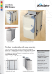
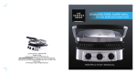
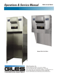
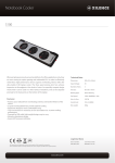
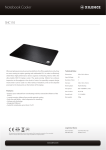
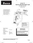
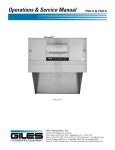
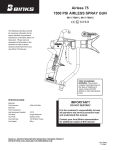
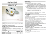
ZW4 Automatic Waxer User's Manual Z Corporation ZTMW4 Automatic Waxer User's Manual Version 1.0 1-1 Z Corporation ZW4 Automatic Waxer User's Manual Table of Contents: 1 YOUR ZW4 AUTOMATIC WAXER....................................................................... 1-6 1.1 2 3 INTRODUCTION .......................................................................................... 1-6 1.1.1 OVERVIEW.............................................................................................................................1-6 1.1.2 HOW IT WORKS....................................................................................................................1-6 1.1.3 THE PARTS OF THE ZW4 WAXER....................................................................................1-7 PREPARING THE ZW4 WAXER TO WAX PARTS ............................................... 2-9 2.1 INSTALLING THE WAXER........................................................................... 2-9 2.2 WARMING UP THE WAXER ........................................................................ 2-9 2.3 SAFETY PRECAUTIONS ............................................................................. 2-9 2.3.1 THE WAX ................................................................................................................................2-9 2.3.2 THE DOOR INTERLOCK SWITCH................................................................................. 2-10 2.3.3 THE DOOR LATCH............................................................................................................ 2-10 WAXING PARTS ............................................................................................. 3-11 3.1 OVERVIEW............................................................................................... 3-11 3.2 INSERTING PARTS................................................................................... 3-11 3.3 CYCLE PARAMETERS .............................................................................. 3-11 3.3.1 PREHEAT TIME .................................................................................................................. 3-11 3.3.2 DIP SPEED ......................................................................................................................... 3-12 3.3.3 SOAK TIME .......................................................................................................................... 3-12 3.3.4 POST HEAT TIME............................................................................................................... 3-12 3.3.5 TEMPERATURE UNITS.................................................................................................... 3-12 3.3.6 WAX TEMPERATURE........................................................................................................ 3-12 3.3.7 AIR TEMPERATURE.......................................................................................................... 3-13 3.3.8 SAVING THE DEFAULTS.................................................................................................. 3-13 3.4 RUNNING THE CYCLE............................................................................... 3-13 3.4.1 PREHEAT ............................................................................................................................ 3-13 3.4.2 WAX DIP............................................................................................................................... 3-13 3.4.3 POST HEAT......................................................................................................................... 3-14 3.5 REMOVING THE PARTS............................................................................ 3-14 3.6 STANDBY (IDLE MODE) ............................................................................ 3-14 1-2 ZW4 Automatic Waxer User's Manual 4 MAINTENANCE ............................................................................................... 4-15 4.1 ROUTINE MAINTENANCE.......................................................................... 4-15 4.1.1 4.2 5 Z Corporation INSERTING ADDITIONAL WAX ....................................................................................... 4-15 SERVICE AND WARRANTY INFORMATION ............................................... 4-15 APPENDIX ...................................................................................................... 5-16 5.1 DESCRIPTION OF MAIN CONTROL PANEL OPTIONS ................................ 5-16 5.1.1 THE FRONT PANEL .......................................................................................................... 5-16 5.1.2 THE WAXER MENU STRUCTURE................................................................................. 5-17 5.2 DESCRIPTION OF REAR POWER INPUT PANEL....................................... 5-18 5.3 SYMBOLS USED....................................................................................... 5-18 5.4 SYSTEM SPECIFICATIONS....................................................................... 5-18 5.5 COMPLIANCE NOTICES............................................................................ 5-19 5.5.1 GENERAL SAFETY............................................................................................................ 5-19 5.5.2 FCC NOTICE ...................................................................................................................... 5-19 5.5.3 CE NOTICES ...................................................................................................................... 5-19 5.6 MATERIAL STORAGE PRECAUTIONS ....................................................... 5-19 5-19 6 INDEX ............................................................................................................... 6-2 1-3 Z Corporation ZW4 Automatic Waxer User's Manual The ZTMW4 Automatic Waxer was manufactured as an accessory to the Z™402 Rapid Prototyping System. The Z402 Rapid Prototyping System is manufactured under patent license to be used for the fabrication of appearance models and facsimile prototypes. Other uses of these items may be restricted; contact Z Corporation for further information. Z Corporation equipment is intended to be used by design engineers and other professionals in the production of early-stage 3-D appearance models. Z Corporation equipment is not to be used to produce, either directly or indirectly, medical or other products that may require precise dimensions or tolerances to ensure the safe and effective operation of such products. You agree to indemnify, defend and hold Z Corporation and its officers, directors and employees harmless from and against any and all claims, losses, damages, costs and expenses resulting from any use of Z Corporation equipment other than for the production of early-stage appearance models. 1-4 ZW4 Automatic Waxer User's Manual Z Corporation Table of Figures Figure 1 – ZW4 Waxer.................................................................................................... 1-7 Figure 2 – ZW4 Waxer Main Control Panel........................................................................ 1-8 Figure 3 – Proper Fill Level of ZW4 Waxer Tank ............................................................. 4-15 Figure 4 – ZW4 Waxer Menu Structure........................................................................... 5-17 Figure 5 – ZW4 Waxer Power Entry................................................................................ 5-18 1-5 Z Corporation ZW4 Automatic Waxer User's Manual 1 YOUR ZW4 AUTOMATIC WAXER 1.1 1.1.1 INTRODUCTION OVERVIEW The ZW4 Waxer is a companion to the Z402 Rapid Prototyping System. It is designed to automatically infiltrate parts made on the Z402 with paraffin wax. This ZW4 Automatic Waxer User's Manual will speed you through this process. The manual contains the following sections: 1. Introduction. This section will give you an overview of the ZW4 Waxer, familiarize you with the terminology we will use to describe the ZW4 Waxer and introduce you to some of the features of this manual. 2. Preparing the ZW4 Waxer to Wax Parts. Preparing the waxer unit to infiltrate parts is as simple as turning on the power switch and setting the desired cycle parameters. 3. Waxing Parts Using the ZW4 Unit. This section will guide you through the process of preheating a part, running the dip cycle and post-heating. 4. Maintenance. Here we review a few preventative maintenance steps and tell you where to go if you experience any problems with the system. 5. Appendix. Useful reference and technical information on the ZW4 Waxer. 6. Index. 1.1.2 HOW IT WORKS The ZW4 Waxer is a companion to the Z402 Rapid Prototyping System. The Z402 System produces appearance models using the Massachusetts Institute of Technology’s patented 3DP (Three-Dimensional Printing) technology. When models first come out of the Z402 system they are porous, and can be infiltrated with a variety of materials. Infiltrating with wax is a quick, versatile and inexpensive method for producing parts with additional strength or preparing parts for further post-processing. After a warm-up period, the ZW4 maintains a bath of liquid wax at a constant temperature. Models made by the Z402 are placed inside the ZW4 Waxer, either on a tray or directly into the unit’s gondola. Before the parts are dipped in the wax bath, they are preheated inside the ZW4 Waxer. Preheating thoroughly dries the parts and raises their temperature to match that of the wax bath. After the preheat cycle, the unit lowers the gondola containing the parts into the wax bath. During a brief dip, the wax soaks into the porous part, completely infiltrating it with wax. 1-6 ZW4 Automatic Waxer User's Manual Z Corporation After infiltration, the gondola is automatically raised and the parts enter the post-heat cycle. Post-heat allows the wax to form a smooth outer surface on the parts. Once post-heat cycle is complete, the parts are removed from the gondola and set out on paper towels or another absorbent material to cool. At this point, additional detail finishing may be done with a hot air gun. Parts are then ready for final use, or for additional processing steps if desired. Infiltration of Z402 models with wax is a simple, quick and inexpensive way to improve part strength and surface finish, and to prepare models for other subsequent post-processing steps. 1.1.3 THE PARTS OF THE ZW4 WAXER Main Control Panel Power Switch Door Latch Gondola Front Door Wax Tank Power Inlet Figure 1 – ZW4 Waxer 1-7 Z Corporation ZW4 Automatic Waxer User's Manual CYCLE START CYCLE RESET Figure 2 – ZW4 Waxer Main Control Panel 1-8 ZW4 Automatic Waxer User's Manual Z Corporation 2 PREPARING THE ZW4 WAXER TO WAX PARTS 2.1 INSTALLING THE WAXER To operate safely, the ZW4 Waxer should be placed on a level surface. The unit is equipped with built-in leveling feet, which can be used to make any final adjustments or to compensate for uneven surfaces. Installation of the unit consists of inserting the power cord into the unit’s power inlet receptacle, located in the rear of the unit near the base, and connecting it to a standard wall outlet. The Waxer is available in 3 versions; 115 volts for the US market; 230 volts for Europe and elsewhere, and 100V for the Japanese market. Check the nameplate rating for the correct voltage before plugging it in. The ZW4 Waxer requires a circuit capable of supplying up to 1200 Watts for it’s safe operation. The ZW4 Waxer is now ready to go to work. 2.2 WARMING UP THE WAXER Warming up the ZW4 Waxer is as easy as turning on the power switch located on the front of the unit. The ZW4 Waxer will automatically begin the process of bringing the wax up to the proper temperature. The initial warm-up cycle usually takes 2 to 3 hours. During the warm-up cycle, the ZW4 Waxer will display ‘Cold’ and the current wax temperatures on the LCD display; during this time only the wax is heated. Once the wax is up to temperature, the ZW4 Waxer will display ‘Warming’. This cycle will last 45 minutes. This allows any residual solid wax to melt; also the gondola area is pre-heated to be ready for use. If the wax has completely melted, the warm-up cycle may be aborted by pressing the ‘Cycle Reset’ key; the ZW4 Waxer will proceed to the ‘Ready’ state. Once the warm-up cycle is complete, the ZW4 Waxer will maintain the liquid wax at the correct temperature until the unit is switched off or put on standby. It will display ‘Ready’ on the LCD display. 2.3 SAFETY PRECAUTIONS Several safety devices are built into the design of the ZW4 Waxer. Normal precautions should be taken around the hot wax and the interior of the oven enclosure. It is normal for the exterior of the Waxer to be warm to the touch when running. 2.3.1 THE WAX The temperature of the liquid wax is normally maintained between 145°F and 175°F (65°C and 80°C). The design of the ZW4 Waxer prevents direct operator access to the liquid wax bath. Nonetheless, care should be taken when inserting or removing parts to avoid contact with any liquid wax. Similarly, the interior surfaces of the unit, such as the gondola and associated trays, may be hot to the touch. Infiltrated parts are also initially hot just after completing the dip cycle. Please exercise caution when inserting or removing parts from the ZW4 Waxer. 2-9 Z Corporation 2.3.2 ZW4 Automatic Waxer User's Manual THE DOOR INTERLOCK SWITCH The ZW4 Waxer is equipped with an interlock switch which prevents movement of the gondola when the front door is open. After placing parts in the ZW4 Waxer for waxing, the front door of the unit should be securely closed. Air heating will not occur and the dip cycle will not begin with the front door of the unit open. 2.3.3 THE DOOR LATCH In order to protect the operator from the hazards of the moving gondola inside the unit, the front door of the ZW4 Waxer is automatically latched closed when the gondola begins it’s downward movement during the dip cycle. Once the dip cycle is complete and the gondola has returned to the idle position, the latch is released and the door can once again be opened. See Figure 1 for an illustration of the door latch. Operation of the Waxer with the door switch / door latch combination defeated will expose the user to pinch hazards from the moving gondola and temperature hazards from hot air and the hot wax. 2-10 ZW4 Automatic Waxer User's Manual Z Corporation 3 WAXING PARTS 3.1 OVERVIEW A waxing cycle consists of three basic parts – the preheat, the wax dip, and the post heat. During the preheat interval, the parts will be thoroughly dried and heated to a temperature slightly higher than that of the wax bath. During the wax dip, the parts are infiltrated with the liquid wax. Following the wax dip is the post heat interval, which allows the excess wax to drain. 3.2 INSERTING PARTS Parts are inserted into the ZW4 Waxer through the front door. When the waxer displays ‘Ready…’, parts can be inserted directly into the gondola or arranged on the tray depending on the size and quantity of parts to be infiltrated. Several parts may be inserted into the unit at once. Once the parts have been inserted, close the front door. 3.3 CYCLE PARAMETERS The default parameters controlling the waxing cycle are stored in the ZW4 Waxer in non-volatile memory. These parameters may be modified using the setup menus. The pre-heat and post-heat times may be modified ‘on the fly’ during the cycle if desired. To change the cycle parameters, press the MENU key while the waxer is either warming or ready. The first item that shows in the menu is ‘Go to Idle Mode? N’. Press the MENU key again, without pressing an arrow key to continue the setup process. The next item that shows will be ‘Load Defaults? N’. If you want modify the currently active values, press the MENU key again. If you want to load the power up default values before doing modifications, press an arrow key to change the display to ‘Load Defaults? Y’, then press the MENU key. After this the setup will bring up a series of choices; use the up and down arrow keys to modify each choice. Pressing the MENU key will accept that choice and move to the next option. 3.3.1 PREHEAT TIME The first setup value is the preheat time. Pressing the MENU key with ‘Change Setup’ showing will bring up the ‘Preheat:’ display. The value shown is the currently programmed number of minutes to preheat the parts. Use the up and down arrow keys to change the number of minutes. The minimum is zero and the maximum is 120 minutes (2 hours). Press the MENU key again to accept the number shown and go on to the next item. Note: You can also change this number during the pre-heat interval by pressing the up and down arrow keys. Rather than constantly using the ‘Change Setup’ menu to modify only the preheat time, it may be more useful to preset a nominal amount of time (say 10 minutes), and use the live arrow keys to modify the preheat time on a batch by batch basis. 3-11 Z Corporation ZW4 Automatic Waxer User's Manual The purpose of the preheat segment is to dry out the parts and bring them up to temperature. To infiltrate parts with wax, the parts must be hot and dry. Drying time and the part’s wall thickness are directly related. If the average wall thickness is ¼”, then the part should be in the preheat segment for ¼ hour or fifteen minutes. If average wall thickness is ½” inch, the length of the preheat segment should be ½ hour. Use the chart below as a guide. Average Wall Thickness Preheat Time 1/8” 10 minutes ¼” 15 minutes ½” 30 minutes 1” or greater 60 minutes For parts with average wall thickness greater than one inch, preheat time should not exceed one hour. Dramatically over drying a part will lead to undesirable shrinkage, while dramatic under drying will lead to part softening. During the wax dip, wax should quickly penetrate the part; if the part floats, it was not thoroughly dried and heated resulting in the formation of air pockets within the part. 3.3.2 DIP SPEED The next setup value is the dip speed. Use the up and down arrow keys to alternate between ‘Dip Speed: High’ and ‘Dip Speed: Low’. Press the MENU key to accept the setting and go to the next. Dip speed refers to speed of the elevator as it lowers the gondola into the wax bath. Choices are limited to high or low speed. Use the low speed for heavy or hollow parts that may trap air and tend to float. 3.3.3 SOAK TIME The next setup value is the number of seconds to leave the gondola in the lowered position. The value shown is in seconds. Use the up and down arrow keys to change the time shown. Press the MENU key to accept the setting and go to the next. Ten seconds should be adequate for most parts. 3.3.4 POST HEAT TIME The next setup value is the number of minutes to heat the part after it has been dipped in wax. Use the up and down arrow keys to change the time shown. Press the MENU key to accept the setting and go to the next. The minimum is zero and the maximum is 120 minutes (2 hours). The post-heat interval allows excess wax to drain from the infiltrated parts. Five or ten minutes of post heating time should be enough to allow the excess wax to drain out of most parts. 3.3.5 TEMPERATURE UNITS The next setup value controls the displayed units used for temperature settings and read outs. Use the up and down arrow keys to choose between ‘Temp Units: ºF’ and ‘Temp Units: ºC’. Press the MENU key to accept the setting and go to the next. Note: The temperature values previously set will be automatically converted. 3.3.6 WAX TEMPERATURE The next setup value is the temperature of the liquid wax bath, which is constantly maintained by the ZW4 Waxer, except when it is put in the ‘Idle’ condition. Use the up and down arrow keys to 3-12 ZW4 Automatic Waxer User's Manual Z Corporation change the temperature shown. Press the MENU key to accept the setting and go to the next. The minimum is 75ºF (23ºC) and the maximum is 175ºF (79ºC). For operation with Z Corporation #10434 wax, this parameter should be set to 145ºF (63ºC). 3.3.7 AIR TEMPERATURE The next setup value is the temperature the air is heated to during the pre and post heat phases of the waxing cycle. Use the up and down arrow keys to change the time shown. Press the MENU key to accept the setting and go to the next. The minimum is 75ºF (23ºC) and the maximum is 180ºF (82ºC). This parameter is usually set at about 20ºF (10ºC) greater than the wax temperature. It should normally be set to 165ºF (74ºC). 3.3.8 SAVING THE DEFAULTS The next choice given is whether or not to save the values chosen as the power up defaults. Use the up and down arrow keys to choose between ‘Save Defaults? N’ and ‘Save Defaults? Y’. In either case, the new values chosen will take effect when the MENU key is pressed again. If the ‘Save Defaults? Y’ option is showing when the MENU key is pressed however, the values chosen will be save in non-volatile memory and will be re-loaded if the power is cycled or when ‘Idle’ mode is exited. When the MENU key is pressed, the waxer display will change to either ‘Warming’ or ‘Cold’ while the temperature setting stabilizes. If the wax is at or above the desired temperature, pressing the ‘CYCLE RESET’ button will change the display to ‘Ready’ before the programmed 45 minute warm-up has elapsed. 3.4 RUNNING THE CYCLE Once the cycle parameters have been entered, the operator can run the cycle by pressing the “CYCLE START” button on the main control panel. Once the “CYCLE START” button has been pressed by the operator, the dip cycle is fully automatic. A beep will signal the end of the post-heat period. The parts can then be removed. Note: The cycle can be aborted at any time by pressing the “CYCLE RESET” button. 3.4.1 PREHEAT The preheat cycle begins immediately when the “CYCLE START” button is pressed. The time remaining in the preheat cycle will be continuously visible in the display area on the main control panel. Pressing the up and down arrows will change the amount of time remaining, either adding or subtracting a minute at a time. This allows for easy ‘on the fly’ changing without changing the defaults. At the end of the preheat cycle, the ZW4 Waxer will immediately move into the wax dip portion of the cycle. 3.4.2 WAX DIP During the wax dip cycle, the elevator of the ZW4 Waxer will lower the gondola and any trays containing parts into the liquid wax bath. Once the elevator begins it’s movement, the front door of the ZW4 Waxer will be latched closed. After pausing at the bottom for a preset length of time, the elevator will reverse and the gondola will be raised out of the wax bath. The ZW4 Waxer will then enter the postheat phase. 3-13 Z Corporation ZW4 Automatic Waxer User's Manual Warning: For safety reasons, the front door of the ZW4 Waxer must remain closed during the wax dip portion of the cycle. The elevator will not move unless the front door is closed completely. Once the elevator has started down, the door will be latched shut; it can be opened again only after the gondola returns to the full up position. 3.4.3 POST HEAT The post-heat cycle allows excess wax to drain from the parts and allows the wax on the exterior of the part to form a solid skin. The time remaining in the post-heat cycle will be visible in the display area of the main control panel. 3.5 REMOVING THE PARTS Three beeps will signal the end of the post heat cycle. At this time, the front door of the ZW4 Waxer may be opened and the parts removed. Caution: The interior of the ZW4 Waxer oven enclosure, as well as the parts themselves, will be hot to the touch. Exercise care when removing or handling parts. Parts may be removed individually, or the operator may choose to remove the gondola tray and parts together. Heating with a hot air gun at this time will allow any internal pools of wax to drain. After removal, the parts can be transferred to a sorbent pad or to paper towels to air cool. Any final blemishes can then be removed with a hot air gun. (Caution: Remove parts from sorbent pad or paper towels while heating with the hot air gun) 3.6 STANDBY (IDLE MODE) If the ZW4 Waxer is not going to be used for an extended period, such as overnight or over a weekend, it may be put into ‘IDLE’ mode. Press the ‘MENU’ key; the display will read ‘Go to Idle Mode’. Pressing the ‘MENU’ key again will enter the idle mode. The ZW4 Waxer will display ‘Waxer is Idle; Press Start’ while in the ‘IDLE’ mode. Press the ‘Cycle Start’ key to start the standard warm up cycle. While in the ‘IDLE’ state, the ZW4 Waxer will keep the wax in a barely liquid state, and will not heat the air at all. This reduces the power required while allowing a warm up time to the ready state of less than one hour. 3-14 ZW4 Automatic Waxer User's Manual Z Corporation 4 MAINTENANCE 4.1 4.1.1 ROUTINE MAINTENANCE INSERTING ADDITIONAL WAX The wax bath in the ZW4 Waxer will periodically require replenishment. This is easily done by opening additional bags of wax and pouring the wax between the gondola and the interior of the oven enclosure. Fill with wax to approximately ½” from the top of the wax tank. Do not overfill. Do not allow level of wax to rise into the overflow section of the wax tank. See Figure 3. Warning: The ZW4 Waxer is equipped with safety features to prevent overflow of the liquid wax. Overfilling the tank with wax may trigger these safety features and not allow the ZW4 Waxer to operate. Wax overflow sensor Proper wax fill level Figure 3 – Proper Fill Level of ZW4 Waxer Tank 4.2 SERVICE AND WARRANTY INFORMATION Your ZW4 Waxer comes with a 90-day warranty, which begins on your installation date and includes parts and labor. Service contracts are available, which cover all repairs, and routine maintenance.. To have your ZW4 Waxer serviced by an authorized Z Corporation Representative, call (617) 628-2871. 4-15 Z Corporation ZW4 Automatic Waxer User's Manual 5 APPENDIX 5.1 5.1.1 DESCRIPTION OF MAIN CONTROL PANEL OPTIONS THE FRONT PANEL CYCLE START CYCLE RESET • MENU Button. Pressing the MENU button once brings up four choices; use the up and down arrow keys to display the desired choice, then press the MENU key again to continue with that choice. Menu options include: • Go to Idle Mode – The waxer will run at reduced temperature to conserve energy yet allow quick (45 minutes) warm up. • Load Defaults – The waxer will load the default values previously saved, then proceed to the Change Setup menu. See section 3.3 for the setup choices. • Changing Setup – The waxer will cycle through parameters that can be adjusted by the operator. See section 3.3 for the setup choices. • UP/DOWN ARROW Buttons. Allows operator to change parameter currently visible in display. • CYCLE START Button. Begins dip cycle when pressed. Also used to re-start the waxer after it has been in the ‘Idle’ mode. • CYCLE RESET Button. Aborts current cycle when pressed. Returns gondola to up position and resets unit to idle mode. Also used to shorten the warm-up cycle. 5-16 ZW4 Automatic Waxer User's Manual 5.1.2 Z Corporation THE WAXER MENU STRUCTURE Cold... MENU Warming... CYCLE START OR CYCLE RESET MENU MENU Ready... Go To Idle Y/N N CYCLE START Preheat 05:00 Load Defaults Y/N Y Waxer is Idle / Press Start Arrows toggle Yes / No Y Loading Defaults... N Dip Speed: High/Low Preheat: 5 m Arrows change time MENU Soak 10 s CYCLE RESET Arrows select HIGH/LOW Dip Speed MENU Raise... Soak time: 10 s Arrows change time MENU Postheat: 05:00 Postheat: 5 m Arrows change time MENU Temp Units: °F Arrows select F or C MENU Wax Temp: 145°F Arrows change temperature MENU Air Temp: 155°F Arrows change temperature MENU MENU Save Defaults? N Arrows toggle display Save Defaults? Y MENU Saving... Figure 4 – ZW4 Waxer Menu Structure 5-17 Z Corporation 5.2 ZW4 Automatic Waxer User's Manual DESCRIPTION OF REAR POWER INPUT PANEL Power Inlet Main Circuit Breaker 12 A M P Figure 5 – ZW4 Waxer Power Entry Power Inlet: Connect, using the detachable power cord supplied with the system, to a standard wall outlet. Check the nameplate rating before plugging in. Replacement power cords are available from Z Corporation. Main Circuit Breaker: A white band will show at the top of the breaker switch if it is tripped. This breaker provides protection from shock and fire hazard in case of a severe problem with the waxer. If this breaker should trip, it could indicate a serious failure; contact your Z Corporation customer service representative. 5.3 SYMBOLS USED The following symbols are used on the ZW4 Waxer: This is the international symbol for ‘warning’ or ‘caution’. It indicates the need to consult your manual for further information. This symbol is used on the rear of the ZW4 Waxer, on the lower right. It is used to call your attention to the fact that only authorized personnel should open the ZW4 Waxer rear cover. None of the normal operation and maintenance procedures described in this manual require you to remove this cover. 5.4 SYSTEM SPECIFICATIONS Dimensions: 18” x 20” x 50” high (46cm x 51cm x 130cm) Weight(empty): 200 lbs. (91kg) ZW4 Waxer Wax capacity: 39.6 lbs. (18kg) Shipping Crate: 135 lbs. (61kg) Power requirements: 5-18 ZW4 Automatic Waxer User's Manual Z Corporation 115 Volt model: 115V ±10%, 60Hz, 9.5 A maximum; ~2 A at idle 230 Volt model: 230V ±10%, 50/60Hz, 5.5 A maxim; ~1.5 A at idle 100 Volt model: 100V ±10%, 50/60Hz, 12 A maximum, ~3 A at idle Operating Conditions: 68 to 85 °F, 20 to 60% Relative Humidity, Non-Condensing 5.5 5.5.1 COMPLIANCE NOTICES GENERAL SAFETY This equipment is not designed for household use. Use with any material not recommended or supplied by Z Corporation may cause a safety hazard. For continued protection against shock hazard, this equipment requires a power connection that includes a safety (protective earth) ground conductor. 5.5.2 FCC NOTICE The 115 Volt version of the ZW4 waxer has been tested and found to comply with FCC Regulations, (CFR 47 Part 15.21 and 15.105) for Class A devices. It is not meant for household use. These limits are designed to provide reasonable protection against harmful interference when the equipment is operated in a commercial environment. This equipment generates, uses, and can radiate radio frequency energy and, if not installed and used in accordance with the instruction manual, may cause harmful interface to radio communications. Operation of this equipment in a residential area is likely to cause harmful interference in which as the user will be required to correct the interference at his own expense. 5.5.3 CE NOTICES The 230 Volt version of the ZW4 waxer has been tested and found to comply with the requirements for CE marking. You may request a copy of the CE declaration from your distributor. The 230 Volt version of the ZW4 waxer complies with the RF emission requirements for Class B (household) equipment, however this equipment is not designed for household use. The 230 Volt version of the ZW4 waxer has been tested and found to comply with RF immunity requirements as described in EN50081-1. 5.6 MATERIAL STORAGE PRECAUTIONS Keep wax containers closed when not in use. Store in a cool, dry, well ventilated area. 5-19 Z Corporation ZW4 Automatic Waxer User's Manual 6 INDEX 3 3DP, 1-5 A Aborting Cycle, 5-15 Adding Wax, 4-14 Air Temperature, 3-12 Arrow buttons, 5-15 C Compliance, 5-18 Control Panel, 1-7, 5-15 Cycle Parameters, 3-10 CYCLE RESET Button, 3-12, 5-15 CYCLE START Button, 3-12, 5-15 D Dimensions, 5-17 Dip Speed, 3-11 Door Interlock Switch, 2-9 Door Latch, 2-9 Drying Parts, 3-10 F Fill Level, 4-14 Finishing, 3-13 G Gondola, 3-10, 3-12 Grounding, 5-18 I Idle Mode, 3-13 Inserting Parts, 3-10 Installing, 2-8 L Layout, 1-6 M Maintenance, 4-14 6-2 Z Corporation ZW4 Automatic Waxer User's Manual Massachusetts Institute of Technology, 1-5 Material Storage, 5-18 MENU Button, 5-15 O , 5-18 Overfilling Wax Tank, 4-14 P Post heat, 3-13 Postheat time, 3-11 Power Input, 5-17 Power Requirements, 2-8, 5-17 Preheat, 3-12 Preheat, 3-10 R Removing the parts, 3-13 S Safety Precautions, 2-8, 4-14 Saving Defaults, 3-12 Service Information, 4-14 Soak Time, 3-11 Symbols, 5-17 System Specifications, 5-17 T Temperature units, 3-11 Three-Dimensional Printing, 1-5 W Warming Up, 2-8 Warranty Information, 4-14 Wax Dip, 3-12 Wax Temperature, 3-12 Waxing Cycle, 3-10 Z Z402 Rapid Prototyping System, 1-3, 1-5 6-2