1
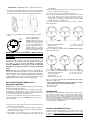
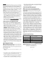
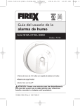
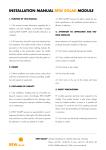
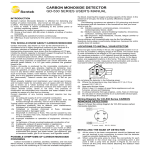
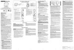
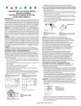
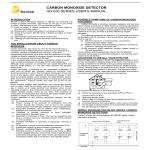
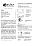
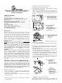
˙ Install a minimum of two detectors in any household.
˙ Install a smoke detector inside every bedroom.
SINGLE MULTIPLE STATION PHOTOELETRIC
SMOKE DETECTOR SD-218 SERIES
USER’S MANUAL
TABLE OF CONTENTS
INTRODUCTION………………………………..……………………………1
LOCATIONS TO INSTALL YOUR SMOKE DETECTOR …………………...1
LOCATIONS TO INSTALL YOUR SMOKE DETECTORS IN MOBILE
HOMES AND RVs………………………………………………………………..3
LOCATIONS NOT TO INSTALL YOUR SMOKE DETECTOR…..………….3
INSTALLING YOUR SMOKE DETECTOR ………………………...….. . . ..4
HOW TO INTERCONNECT MODEL SD-218*-I DETECTORS
TOGETHER………………………………………………………………………..5
RED LED INDICATOR………………………………………………..………..7
TESTING YOUR SMOKE DETECTOR………………………………………7
TAKING CARE OF YOUR SMOKE DETECTOR ………………...…………..7
HEAT SENSOR TESTING………………………………………………………8
FIVE YEAR LIMITED WARRANTY ……………………………….………..…8
INTRODUCTION
SENTEK’s single station photoelectric smoke detector is designed
to sense smoke that comes into the detector chamber. It does not
sense gas, heat, or flame. This smoke detector is designed to give
early warning of developing fires by giving of f the alarm sounds from
its built-in alarm horn. It can provide precious time f or you and your
family to escape before a fire spreads. However, the smoke detector
makes such pre-warning of f ire accident possible, only if the
detector is located, installed, and maintained properly as described
in this User's Manual.
WARNING: This smoke detector is designed for use in a single residential
unit only, which means that it should be used inside a single family home or
apartment. It is not meant to be used in lobbies, hallways, basements, or
another apartment in multi-family buildings, unless there are already working
detectors in each family unit. Smoke detectors, placed in common areas
outside of the individual living unit, such as on porches or in hallways, may not
provide early warning to residents. In multi-family buildings, each family living
unit should set up its own
detectors.
WARNING: This detector is not meant to be used in non-residential
buildings. Warehouses, industrial or commercial buildings, and special
purpose non-residential buildings require special fire detection and alarm
systems. This detector alone is not a suitable substitute for complete fire
detection systems for places where many people live or work, such as hotels
or motels. The same is true of dormitories, hospitals, nursing homes or group
homes of any kind, even if they were once single family homes. Please refer
NFPA 101, the Life Safety Code, NFPA71, 72A, 72B, 72C, 72D, and 72E for
smoke detector requirements for fire protection in buildings not defined as
“households”.
˙ Install smoke detectors at both ends of a bedroom hallway if
is more than 40 feet (12 meters) long.
the hallway
˙ Install a smoke detector inside every room where one sleeps with the door
partly or completely closed, since smoke could be blocked by the closed
door and a hallway alarm may not wake up the sleeper if the door is
closed.
Figure 1:LOCATIONS FOR PLACING
SMOKE DETECTORS FOR
SINGLE RESIDENCE WITH
ONLY ONE SLEEPING AREA
Figure 2: LOCATIONS FOR
PLACING SMOKE
DETECTORS FOR
SINGLE-FLOOR RESIDENCE
WITH MORE THAN ONE
SLEEPING AREA
Figure 3: LOCATION FOR PLACING
SMOKE DETECTORS FOR
A MULTI-FLOOR
RESIDENCE
˙ Install basement detectors at the
bottom of the basement stairwell.
˙ Install second-floor detectors at the top of the first-to-second floor stairwell.
Be sure no door or other obstruction blocks the path of smoke to the detector.
˙ Install additional detectors in your living room, dining room, family room,
attic, utility and storage rooms.
˙ Install smoke detectors as close to the center of the ceiling as possible. If
this is not practical, put the detector on the ceiling, no closer than 4 inches
(10 cm) from any wall or corner, as shown in Figure 4.
˙ If ceiling mounting is not possible and wall mounting is permitted by your
local and state codes, put wall-mounted detectors between 4 and 6 inches
(10 ~ 15 cm) from the ceiling, also see Figure 4.
˙ If some of your rooms have sloped, peaked, or gabled ceilings, try to mount
detectors 3 feet (0.9 meter) measured horizontally from the highest point of
the ceiling as shown in Figure 5.
Figure 4: RECOMMENDED
BEST AND
ACCEPTABLE
LOCATIONS TO MOUNT
SMOKE DETECTORS
LOCATIONS TO INSTALL YOUR SMOKE DETECTOR
Smoke detectors should be installed in accordance with the NFPA Standard
74 (National Fire Protection Association, Batterymarch Park, Quincy, MA
02169). For complete coverage in residential units, smoke detectors should
be installed in all rooms, halls, storage areas, basements, and attics in each
family living unit. Minimum coverage is one detector on each floor and one in
each sleeping area. and attics in each family living unit. Minimum coverage is
one detector on each floor and one in each sleeping area.
Figure 5:
RECOMMENDED
Here, we have useful tips for you:
LOCATION TO MOUNT
SMOKE DETECTORS
IN ROOMS WITH
SLOPED, GABLED, OR
PEAKEDCEILING
˙ Install a smoke detector in the hallway outside every separate bedroom
area, as shown in Figure 1. Two detectors are required in homes with two
bedroom areas, as shown in Figure 2.
˙ Install a smoke detector on every floor of a multi-floor home or apartment,
as shown in Figure 3.
2
1
˙ Install a smoke detector on every floor of a multi-floor home or apartment,
as shown in Figure 3.
△ CAUTION (As required by State Fire Marshall)
“Early warning fire detection is best achieved by the installation of fire
detection equipment in all rooms and areas of the household as follows: (1) A
smoke detector installed in each separate sleeping area (in the vicinity, but
outside of the bedrooms), and (2) Heat or smoke detectors in the living
rooms, dining rooms, bedrooms, kitchens, hallways, attics, furnace rooms,
closets, utility and, storage rooms, basements and attached garages.”
For your information, NFPA Standard 74, Section 2-4 reads as follows:
“2-4.1.1 Smoke detectors shall be installed outside of each separate sleeping
area in the immediate vicinity of the bedrooms and on each additional story of
the family living unit including basements and excluding crawl spaces and
unfinished attics.
The provisions of 2-4.1.1 represent the minimum number of detectors
required by this standard. It is recommended that the householder consider
the use of additional smoke detectors for increased protection for those
areas separated by a door from the areas protected by the required smoke
detectors under 2-4.1.1 above. The recommended additional areas are living
room, dining room, bedroom(s), kitchen, attic (finished or unfinished), furnace
rooms, utility room, basement, integral or attached garage, and hallways not
included in 2-4.1.1 above. However, the use of additional detectors remains
the option of the householder.” We recommend complete coverage and use
of additional smoke detectors.
LOCATIONS TO INSTALL YOUR SMOKE DETECTORS
IN MOBILE HOMES AND RVs
Mobile homes and RVs built after about 1978 were designed and insulated to
be energy-efficient. In mobile homes and RVs built after 1978, smoke
detectors should be installed as described above. Older mobile homes and
RVs may have little or no insulation compared to current standards. Outside
walls and roofs are often made of non-insulated metal, which can transfer
thermal energy flow from outdoors. This makes the air right next to them
hotter or colder than the rest of the inside air. These layers of hotter or colder
air can keep smoke from reaching a smoke detector. Thereby, install smoke
detectors in such units only on inside walls. Place them between 4 and 6
inches (10 ~ 15 cm) from the ceiling. If you are not sure how much insulation
is in your mobile home or RV, then install the detector on an inside wall. If the
walls or ceiling are unusually hot or cold, then install the detector on an inside
wall. Install one detector as close to the sleeping area as possible for
minimum security, or install one detector in each room for security. Before you
install any detector, please read the following section on “LOCATIONS NOT
TO INSTALL YOUR SMOKE DETECTORS”.
LOCATIONS NOT TO INSTALL YOUR SMOKE
DETECTORS
Nuisance alarms take place when smoke detectors are installed where they
will not work properly. To avoid nuisance alarms, do not install smoke
detectors in the following situations:
˙ Combustion particles are the by-products of something that is burning.
Thus, in or near areas where combustion particles are present you do not
install the smoke detectors to avoid nuisance alarms, such as kitchens with
few windows or poor ventilation, garages where there may be vehicle
exhaust, near furnaces, hot water heaters, and space heaters.
˙ Do not install smoke detectors less than 20 feet (6 meters) away from
places where combustion particles are normally present, like kitchens. If a
20-foot distance is not possible, e.g. in a mobile home, try to install the
detector as far away from the combustion particles as possible, preferably
on the wall. To prevent nuisance alarm alarms, provide good ventilation in
such places.
IMPORTANT: For any reason, do not disable the detector to avoid
nuisance alarms.
˙ When air streams passing by kitchens, the way how a detector can sense
combustion particles in normal air-flow paths is graphically shown in Figure
6, which indicates the correct and incorrect smoke detector locations
concerning this problem.
Figure 6: RECOMMENDED
SMOKE DETECTOR
LOCATIONS TO AVOID AIR
STREAMS W ITH COMBUSTION
PARTICLES
3
˙ In damp or very humid areas, or near bathrooms with showers. Moisture in
humid air can enter the sensing chamber, then turns into droplets upon
cooling, which can cause nuisance alarms. Install smoke detectors at least
10 feet (3 meters) away from bathrooms.
˙ In very cold or very hot areas, including unheated buildings or outdoor
rooms. If the temperature goes above or below the operating range of
smoke detector, it will not work properly. The temperature range for your
o
o
o
o
smoke detector is 32 F to 120 F (0 C to 50 C).
˙ In very dusty or dirty areas, dirt and dust can build up on the detector’s
sensing chamber, to make it overly sensitive. Additionally, dust or dirt can
block openings to the sensing chamber and keep the detector from sensing
smoke.
˙ Near fresh air vents or very drafty areas like air conditioners, heaters or
fans, fresh air vents and drafts can drive smoke away from smoke
detectors.
˙ Dead air spaces are often at the top of a peaked roof, or in the corners
between ceilings and walls. Dead air may prevent smoke from reaching a
detector. See Figures 4 and 5 for recommended mounting locations.
˙ In insect-infested areas. If insects enter a detector’s sensing chamber, they
may cause a nuisance alarm. Where bugs are a problem, get rid of them
before putting up a detector.
˙ Near fluorescent lights, electrical “noise” from fluorescent lights may cause
nuisance alarms. Install smoke detectors at least 5 feet (1.5 meters) from
such lights.
WARNING: Never remove batteries to stop a nuisance alarm. Open a window
or fan the air around the detector to get rid of the smoke. The alarm will turn
itself off when the smoke is gone. If nuisance alarms persist, attempt to clean
the detector as described in this User’s Manual.
WARNING: Do not stand close to the detector when the alarm is sounding.
The alarm is loud in order to wake you in an emergency. Too much exposure
to the horn at close range may be harmful to your hearing.
INSTALLING YOUR SMOKE DETECTOR
Model SD-218 series smoke detectors are to be mounted on the ceiling or on
the wall if necessary. Since SD-218 series smoke detector is a single-station
type, it cannot be linked to other detectors. Model SD-218 series with I mark
can serve as a single-station, stand-alone unit, or can be interconnected with
other SD-218 series with I mark detectors. (See “HOW TO CONNECT
SD-218*-I DETECTORS TOGETHER.”)
WARNING: Do not connect the SD-218 series smoke detectors to any other
alarm or auxiliary device. Connecting anything else to this detector will keep it
from working properly.
Read “LOCATIONS TO INSTALL YOUR SMOKE DETECTORS” and
“LOCATIONS NOT TO INSTALL YOUR SMOKE DETECTORS” section in
this Manual first, then decide where to install a detector.
IMPORTANT: For the AC powered model- To avoid the electrical shock
hazard, turn off power to the area where you plan to install the
detector at the fuse box or circuit breaker box
Please follow these steps to install your smoke detector:
1. At the place where you are going to install the detector, draw a horizontal
line six inches long.
2. Remove the mounting bracket from your unit by rotating it
counterclockwise.
3. Place the bracket so that the two longest hole slots are aligned on the line.
In each of keyhole slots, draw a mark to locate a mounting plug and screw.
4. Remove the bracket.
5. Using a 3/16-inch (5mm) drill bit, drills two holes at the marks and insert
plastic wall plugs. Put the detector away from getting plaster dust on it
when you drill holes for mounting.
6. Using the two screws and plastic wall plugs (all supplied), attach the
bracket to the wall.
NOTE: If this detector is to be connected to other detectors, read the
instructions in the Section of “How to Interconnected Model with -I Series
Detector Together” before you finish installing the detector. If the detector
is not for interconnection purpose, do not use the “INTERCONNCT” wire.
For AC powered model, please read the message as following:
A power connector with brown, orange (for interconnection model),
and blue wires is packed with each detector. Use wire nuts to connect
these wires to the AC power supply. Connect the brown wire on the
connector to the brown AC power supply. Connect the blue wire on the
connector to the blue AC wire. While the orange wire is used for
INTERCONNCT mode only. And the red wire is used for 9Vdc output
only.
4
Plug the power connector into other connector attached at the back of the
detector as shown in Figure 7. It is keyed so it can only be installed one
way. Tug the connector to be sure that it is plugged in correctly. The
connector can be removed at any time by holding the connector body
firmly and pulling it out.
WARNING: Do not connect AC power wires to the
“INTERCONNCT” (orange) wire. If doing so, it will damage the detector.
7. Line up the slot of the bracket and the detector. Push the detector onto the
mounting bracket and turn it clockwise to fix it into place. Pull outward on
the detector to make sure it is securely attached to the mounting bracket.
codes that apply.
(5) Wire the interconnection type detectors by connecting the interconnect
connectors on all units together. See figure 9.
(6) Be sure the batteries are properly installed for each detector.
(7) To test the system, push test button on each detector. The alarm horns
on all of the detectors in the system should sound if they are
interconnected correctly. Make sure that all other units in the system
sound an alarm as each unit is tested. Interconnect the detectors within
one family residence area only. Otherwise,
when a detector in another residence is tested, the occurrence of nuisance
alarms may take place.
8. The steps to open the battery cover and to install the battery are listed as
follows:
(1)To power Smoke detector
Battery
requires an alkaline battery.
Cover
(2)Match terminals on the end(s) of
the battery with opposite terminal
connections on the detector. Be
sure to insert the alkaline battery in
the position shown on the detector.
(3)When terminals are properly
matched, push battery firmly in until
it snaps and cannot be shaken
loose.
TO ADDITIONAL DETECTORS
MAX. OF 38 INTERCONNECTED
NOTES FOR INTERCONNECTION:
Blue to Ground
Orange to Interconnection
Figure 9.A: WIRING DIAGRAM FOR INTERCONNECTION MODEL
SD-218 series with I mark
IMPORTANT: For the AC powered model- Whenever placing
or removing battery in the detector, try to disconnect AC
power at the fuse box or circuit breaker to avoid electrical
shock hazard.
CAUTION: This smoke detector comes with cover latches that will
prevent the smoke detector cover from closing if battery is not
installed. This tells you that the smoke detector will not work until a
new battery is properly installed. The battery is purposely
positioned WRONGLY in the factory to keep it fresh until
installation. It must be re-positioned correctly to provide DC
power.
NOTE: When the detector battery first makes contact with the
detector, the alarm horn may sound for one second. This means
normal and indicates that the battery is positioned properly. Close
cover, then press the test button, holding it down for about 5
seconds until the horn sounds. The horn should sound a loud,
pulsating alarm. This means the unit is working properly.
NOTES FOR INTERCONNECTION:
TO ADDITIONAL DETECTORS
MAX. OF 38 INTERCONNECTED
Brown to Hot (Live)
Blue to Neutral
Orange to Interconnection
Figure 9.B: WIRING DIAGRAM FOR INTERCONNECTION MODEL
SD-218-A series with I mark
HOW TO INTERCONNECT MODEL SD-218*-I
DETECTORS TOGETHER
Warning: Failure to follow the installation instructions below could result in
malfunction and damage to the detector.
The SD-218 series with I mark smoke detectors means with "interconnection"
capability may be connected together. Then, if one detector senses smoke,
all of them will sound their alarms. The following conditions must be met to
ensure the interconnected detectors working properly:
(1) The SD-218 series with I mark smoke detector can be interconnected
only to other detectors of the same type. DO NOT connect to any other type
or model smoke alarm.
NOTES FOR NON-INTERCONNECTION AC MODELS, THERE’S NO “ORANGE”
WIRE, PLEASE CONNECT ONLY BLUE AND BROWN WIRES.
Brown to Hot (Live)
Blue to Neutral
RED INDICATOR
The red LED, as the ALARM indicator, is featured with the detector. It can be
seen through the test button on the cover of the detector. When red LED
flashes once 32 seconds, it indicates the detector under normal operation.
When smoke detector senses smoke and simultaneously sounds an audible
alarm, the red LED will flash very frequently, once 0.67 seconds. For the
interconnected system, whereas the red LED does not light, it indicates that
the other detector(s) belonging to the same interconnection system has
sensed smoke and is signaling the alarm.
5
(2) The SD-218 series with I mark smoke detectors may be interconnected
with as many as 38 other detectors.
(3) The total length of wire interconnecting the detectors should be no
more than 1000 feet. The interconnecting wire should be #18 AWG or
larger and be rated at least 300V.
(4) The installation of such detector must be in accordance with the
requirements of Article 760 of the National Electrical Code and any local
6
TESTING YOUR SMOKE DETECTOR
Test the detector weekly by pushing firmly on the test button with your finger
until the horn sounds. Testing method may take up to 20 seconds to sound
the alarm horn. These are only ways to be sure that detector is working
correctly. If the detector fails to test properly, have it repaired or replaced
immediately.
NOTE: For interconnection model SD-218 series with I mark detectors:
When an interconnection system of model SD-218 detectors goes into alarm,
the indicator LED on the only detector(s) sensing smoke will flash for every
0.67 second, while the indicator LED on the rest of detectors will not flash.
WARNING: Never use an open flame to test your detector. You may set
fire to damage the detector, as well as your home. The built-in test switch
accurately tests all detector functions, as required by Underwriters’
Laboratories. They are the only correct ways to test the unit.
WARNING: When you are not testing the unit and the alarm horn sounds a
loud continuous sound, this means the detector has sensed smoke or
combustion particles in the air. Be sure that the alarm horn is a warning of a
possible serious situation, which requires your immediate attention.
˙ The alarm could be caused by a nuisance situation. Cooking smoke or a
dusty furnace, sometimes called “friendly fires” can cause the alarm to
sound. If this happens, open a window or fan the air to remove the smoke
or dust. The alarm will turn off as soon as the air is completely clear.
NOTE: Do not disconnect the battery from the detector. This
will remove your protection from fires.
˙ If the alarm horn begins to beep once a minute, this signal means that the
detector’s battery is weak. Replace new battery immediately. Keep fresh
batteries on hand for this purpose.
TAKING CARE OF YOUR SMOKE DETECTOR
To keep your detector in good working order, you must test the detector
weekly, as referring to section “TESTING YOUR SMOKE DETECTOR”.
˙Replace the detector battery once a year or immediately when the low
battery “beep” signal sounds once 32seconds at same time the LED flash.
The low battery “beep” should last at least 30 days.
NOTE: For replacement battery, use Golden Power G6F22, G6F22M,
GL6F22A, Eveready #522, #1222, #216; Duracell #MN1604; or Gold Peak
#1604P, #1604S, #1604A; or Ultralife U9VL-J.
WARNING: Do not use any other kind of battery. This
detector may not operate properly with other kind of battery.
˙Normal, the LED flashes every 32 seconds. A beep or chirp occurring at
half time of LED flashes, it indicates the detector is fault.
˙ Open the cover and vacuum the dust off the detector’s sensing chamber at
least once a year. This can be done when you open the detector to change
the battery. Remove battery before cleaning. To clean detector, use soft
brush attachment to your vacuum. Carefully remove any dust on detector
components, especially on the openings of the sensing chamber. Replace
battery after cleaning. Test detector to make sure battery is incorrectly.
Check to make sure there are no obstruction inside the test button. If there
is any dust in the test button, insert a toothpick from the back to the front.
NOTE: If nuisance alarms keep coming from the detector, you should
check whether the detector’s location is adequate. Refer to section
“WHERE TO INSTALL SMOKE DETECTORS.” Move your detector if it is
not located properly. Clean detector as described above.
˙ Clean detector cover when it gets dirty. First open the cover and remove
battery. Hand-wash cover with cloth dampened with clean water. Dry it with
lint-free cloth. Do not get any water on the detector components. Replace
the battery, and close cover. Test detector to make sure that battery works
correctly.
5. After testing check that the system is set for normal operation and
notify the appropriate authorities that the testing operation is complete
and the system is active again.
FIVE YEAR LIMITED WARRANTY
NOTE: In order to protect your right, please keep the original
purchase receipt for the proof of buying SENTEK detector from our
authorized dealers. No warranty can be offered without the original
purchase receipt.
SENTEK warrants its enclosed Smoke Detector - but not the battery - to be
free from defects in materials and workmanship under normal use and service
for a period of five years from date of purchase. SENTEK makes no other
express warranty for this smoke detector. No agent, representative, dealer, or
employee of the Company has the authority to increase or alter the obligations
or limitations of this Warranty. The Company’s obligation of this Warranty
shall be limited to the repair or replacement of any part of the detector which
is found to be defective in materials or workmanship under normal use and
service during the five year period commencing with the date of purchase.
During the initial one-year period commencing with the date of purchase, such
repair or replacement shall be made without charge. During the latter four
years of the Warranty period, such repair or replacement shall be made at a
charge to the Customer not to exceed the manufacturer’s cost. Units in need
of repair should be returned, shipping prepaid, to Customer Service
Department, Ningbo Sentek Electronics Co., Ltd. –448 Yingchun Road,
Wangchun Industrial Zpone, Ningbo City 315175, Zhejiang, China.
The Company shall not be obligated to repair or replace units, which are
found to be in need of repair because of damage, unreasonable use,
modifications, or alterations occurring after the date of purchase. The duration
of any implied Warranty, including that of merchantability or fitness for any
particular purpose, shall be limited to the period of five years commencing
with the date of purchase. In no case shall the Company be liable for any
consequential or incidental damages for breach of this or any other Warranty
expressed or implied whatsoever, even if the loss or damage is caused by the
Company’s negligence or fault. Some states do not allow the exclusion or
limitation of incidental or consequential damages, so the above limitation or
exclusion may not apply to you. SENTEK makes no warranty, expressed or
implied, written or oral, including that of merchantability or fitness for any
particular purpose, with respect to the batteries. This Warranty gives you
specific legal rights, and you may also have other rights which vary from state
to state.
SENSOR SPECIFICATION:
:
Smoke Sensitivity:
0.08~0.15dB/m (EN standard)
0.98~2.60%/ft (UL standard)
Temperature Sensitivity
135ºF (57ºC) for with Heat sensor model only
Standby Current:
8µA
Alarm Current:
15mA
Temperature Range
0°C to 50°C
Humidity:
0 to 95% RH, no condensation or icing
Alarm Sound Level
85 db/3m
HEAT SENSOR TESTING
NOTE: For SD218 series detectors that without HEAT DETECTION,
please skip the description of this section).
The detector to be tested should be subject to a flow of warm air at a
temperature between 132ºF and 180 ºF. This requirement can be met
by some domestic hair dryers.
ISSUE NO. SD-218 REV.B
Ningbo Sentek Electronics Co., Ltd. – 488. Yingchun Road, Wangchun
Industrial Zone, Ningbo City 315175, Zhejiang, China.
www.sentek.cc; www.chinabestkey.com
MADE IN CHINA
Proceed as follows:
1. Switch on the warm air flow and check that temperature is correct
and stable.
7
2. From a distance of inches, direct the airflow at the guard protecting
the thermistor. The detector should alarm within 30 seconds.
3. On alarm immediately remove the heat source, check that the
detector’s red LED is lit. Reset the detector from the control panel.
4. If the detector fails to go into alarm within 30 seconds it is too
insensitive and needs to be returned to the distributor for servicing.
8