1
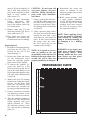
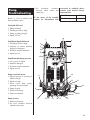
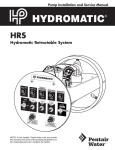
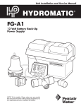
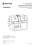
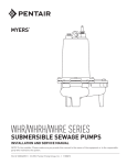
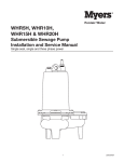
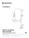
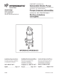
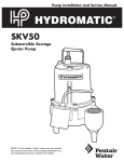
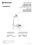
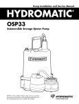
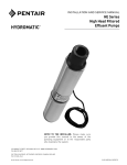
Pump Installation and Service Manual
HPGR200
Submersible Grinder Pump
R
NOTE! To the installer: Please make sure you provide
this manual to the owner of the pumping equipment or to
the responsible party who maintains the system.
General
Information
Thank you for purchasing your
Hydromatic® pump. To help
ensure years of trouble-free
operation, please read the following
manual carefully.
Before Operation:
Read the following instructions
carefully. Reasonable care and
safe methods should be practiced.
Check
local
codes
and
requirements before installation.
Attention:
This manual contains important
information for the safe use of
this product. Read this manual
completely before using this
product and refer to it often for
continued safe product use.
DO NOT THROW AWAY OR
LOSE THIS MANUAL. Keep it
in a safe place so that you may
refer to it often.
WARNING: Before handling
these pumps and controls,
always disconnect the power
first. Do not smoke or use
sparkable electrical devices or
flames in a septic (gaseous) or
possible septic sump.
Pump Cautions
And Warnings
To reduce risk of electrical shock:
1. Risk of Electrical Shock:
This pump has not been
investigated for use in
swimming pool areas.
2. Risk of Electrical Shock:
Connect only to a properly
grounded receptacle.
2
Septic tank to be vented
in accordance with local
plumbing codes.
Do not smoke or use sparkable
electrical devices or flame in a
septic (gaseous) or possible
septic sump.
If a septic sump condition may
exist and if entry into sump is
necessary, then (1) provide
proper safety precautions per
OSHA requirements and (2)
do not enter sump until
these precautions are strictly
adhered to.
Do not install pump in location
classified
as
hazardous
per N.E.C., ANSI/NFPA
70 - 2000.
Failure to heed above
cautions could result in
injury or death.
1. CAUTION - To reduce risk of
electrical shock, pull plug
before servicing this pump.
2. WARNING - Risk of electrical
shock - this pump has not
been investigated for use in a
swimming pool.
3. WARNING - SEE installation
and service manual for
proper installation.
4. WARNING - To reduce risk
of electrical shock pump is
provided with grounding wire.
Be certain that it is connected
to ground.
5. WARNING - Hazardous moving
parts. To reduce the risk of
injury, disconnect power
before servicing pump.
6. CAUTION - To reduce the risk
of electrical shock, DO NOT
remove cord or strain relief.
DO NOT connect conduit to
pump. Electrical installations
shall be in accordance with
the National Electrical Code
and all applicable local codes
and ordinances. This marking
is required on 3 phase
models only.
7. CAUTION - For use with
maximum 140°F water.
8. CAUTION - Tank should be
vented in accordance with
local plumbing codes and
should not be installed
in locations classified as
hazardous, in accordance with
the National Electrical Code,
ANSI/NFPA 70-1999.
9. CAUTION - Risk of electrical
shock. Do not remove cord and
strain relief. Do not connect
conduit to pump.
10.WARNING - Severe injury
may result from accidental
contact with moving cutters.
Keep clothing, hands and feet
away from cutters any time
power is connected to the pump.
11.CAUTION - Never work on
pump with power on. Make
sure that the ground wire is
securely connected and that the
unit is properly grounded in
accordance with local codes.
Pump
Installation
Installing Pump in Sump:
Before installing pump in sump,
lay it on its side and rotate
impeller. Impeller may be
slightly stuck due to factory test
water so it must be broken loose
with a small bar or screwdriver in
edge of vanes. The impeller
should turn freely. Do not connect
the power until after this test.
Clean all trash and sticks from
sump and connect pump to piping.
A check valve must be installed
on each pump.
Location:
If pumps are installed in an
existing basin or concrete sump,
the piping can either be connected
permanently or rails and brackets
can be furnished for mounting to
walls of basin. In either case, be
sure that the Hydromatic nonclog
check valve is used and that the
pumps are submerged in a
vertical position. The complete
factory-built packaged system is
recommended for the most
satisfactory installation and
generally for the lowest cost
where expensive installation labor
is involved.
Making Electrical Connections:
All electrical wiring must be in
accordance with local code, and
only qualified electricians should
make the installations. Complete
wiring diagrams are included for
use in making the installation. All
wires should be checked for shorts
to ground with an ohmmeter or
Megger after the connections are
made. This is important, as one
grounded wire can cause
considerable trouble.
Pump
Operation
Starting the Pump:
WARNING: Severe injury may
result from accidental contact
with moving cutters. Keep
clothing, hands and feet away
from cutters any time power is
connected to the pump.
To start the pump, perform the
following steps in order:
1. Grinder pump is single phase;
no rotation check is necessary.
2. Run water into sump until
motor is covered.
3. Open gate valve in discharge
line.
4. Turn pump on. If pump runs
and sump liquid does not pump
down, stop pump and close
discharge gate valve. Then lift
pump until sealing flange is open
to vent off trapped air. Lower
pump, open discharge valve,
and start the pump again.
5. Level control should be set so
that pump turns off when level
is about 2 inches above inlet
of pump suction and turns on
when level is about 2 inches
above motor.
6. If problems occur check power
source. Make sure a separate
supply line is available. Verify
voltage supply.
7. Check resistance of windings.
(See Chart, page 5.) If not
within guidelines, return pump
to authorized Hydromatic
service or repair center.
As the motors are oil filled, no
lubrication or other maintenance
is required. Pump should be
checked every quarter for
corrosion and wear.
Pump
Servicing
Read the following instructions
carefully before replacing any
parts. Reasonable care and safe
methods should be practiced.
Check
local
codes
and
requirements before installation.
Only a competent electrician
should make the installations.
CAUTION: Never work on
pump with power on. Make sure
that the ground wire is securely
connected and that the unit
is properly grounded in
accordance with local codes.
CAUTION: Severe injury may
result from accidental contact
with moving cutters. Keep
clothing, hands and feet away
from cutters any time power is
connected to the pump.
Replacing Grinder Parts:
If necessary to replace grinder
parts because of wear or to inspect
for clogging:
1. Close gate valve at pump
discharge.
2. Turn off circuit breaker.
CAUTION: Never work on
pump with power on. Be sure
ground wire from pump is
connected to a good ground
such as a water pipe.
3. Remove pump from sump.
4. Unscrew screws (17) and
remove cutter ring retainer
(16). Stationary cutter (15)
cannot be removed from volute
(20).
5. Unscrew hex head cap screws
(12) and remove volute
case (20).
6. Radial cutter (13) and axial
cutter (14) are now exposed. If
checking for clogging, these
parts can now be cleaned
without removing them from
the shaft.
7. If necessary to replace
cutters, remove screw (19),
washer (18), and radial cutter
(13) from shaft. Radial cutter
(13) and impeller (9) are
screwed onto shaft. The thread
is right-hand. Tap radial cutter
(13) with plastic hammer if
necessary to loosen. Axial
3
NOTE: When applying power,
be sure the pump is restrained
from turning by holding the
pump at the motor housing, or
by clamping it in a holding
fixture.
WARNING: Severe injury may
result from accidental contact
with moving cutters. Keep
clothing, hands and feet away
from cutters any time power
is connected to the pump.
PERFORMANCE CURVE
40
35
120
105
30
5-3/
8" DI
A.
90
25
75
20
4-1/4" DIA.
60
15
45
10
30
5
15
0
0
U.S. GPM
M 3/HR
4
9. Reassemble the cutter and
volute as outlined in the
replacing grinder parts section
of this manual.
10.Refill motor housing with
a good quality paraffinic
oil (25). Fill the motor housing
so that the tops of the motor
windings have been covered,
but leave an air gap to allow
for expansion of the oil.
NOTE: It is normal to observe
some air bubbles in the seal
area initially as the seal seats. If
bubbles do not stop within a few
seconds, the seal is either not
properly installed or is damaged.
HEAD (FEET)
Replacing Seal:
1. Drain the oil from the pump by
removing the fill plug (5)
located on the side of the
motor housing (7).
2. Remove the volute and cutters
per the instructions listed
under the replacing grinder
parts section in this manual.
3. To remove the impeller (9),
secure the shaft by a flat
bladed screwdriver into slot on
end of the shaft. Hold a wood
block against the impeller vane
and tap it with a hammer until
it spins off.
4. Remove the seal (24) rotating
elements by sliding the spring
bellows off the shaft, then
using two screwdrivers, slide
the carbon seal assembly off
by prying on the retaining ring.
5. Using a screwdriver, break the
old stationary portion of the
seal (24) to allow for removal.
6. Take the stationary portion of
the new seal (24), and lube the
rubber material with good
quality dielectric oil. Press
the stationary portion of the
new seal into the seal/bearing
plate (21).
CAUTION: Do not reuse old
seal parts. Replace all parts
with new. Mixing old and new
parts could cause immediate
seal failure.
7. Using a good quality dielectric
oil, lube the rubber material on
the carbon seal assembly (24)
and press it on the shaft. Place
the spring bellows on the shaft
as removed.
8. Using a pressure gauge with a
fill stem, pressurize the motor
housing no more than 7 psig
with dried air and check for
leaks. If after several minutes
the gauge reads the same,
the seal is good and you can
continue with assembly.
HEAD (METERS)
cutter (14) lifts off impeller (9)
and is held from rotation by
pin. Unscrew impeller (9) from
shaft in same manner as
radial cutter (13).
8. Clean all parts thoroughly
before
proceeding
with
assembly. Replace case (20),
but do not replace cutter ring
(15) at this point.
9. Replace cutter ring (15) and
cutter ring retainer (16). Screw
down with screws (17).
10.Plug pump into power and
operate for a few seconds only
to ensure parts are not rubbing.
0
7.5
15
2.5
22.5
5
30
37.5
7.5
45
10
52.5
12.5
60
15
Pump
Troubleshooting
3. No
diametral
clearance
between radial cutter and
cutter ring
Below is a list of troubles and
their probable causes:
If the cause of the trouble
cannot be determined and
corrected as outlined above,
contact your nearest factory
representative.
Start Windings
Run Windings
7.53
1.56
No liquid delivered
1. Pump airbound
2. Discharge head too high
3. Pump or piping plugged
4. Speed too low
1
Insufficient liquid delivered
1. Discharge head too high
2. Impeller or cutters partially
plugged or damaged
3. Incorrect impeller diameter
4. Speed too low
6
2
7
3
4
5
25
Insufficient discharge pressure
1. Air or gases in liquid
2. Impeller damaged
3. Incorrect impeller diameter
4. Speed too low
Pump overloads motor
1. Specific gravity or viscosity of
liquid too high
2. Speed too high
3. Head lower than rating,
pumping too much liquid
4. Pump clogged
5. Defective bearings
6. Defective impeller
Pump is noisy
1. Defective bearings
2. No axial clearance between
impeller and volute
8
24
11
22
21
20
9
14
12
16 17
13
18, 19
23
15
5
HPGR200
Typical Installation
NO PANEL REQUIRED
6
HPGR200
Parts List
6
7
25
5
8
24
11
22
21
20
9
23
14
12
Ref. No.
5
6
7
8
9
10
11
12
13
14
15
16
17
18
Part No.
16 17
Description
13
18, 19
Qty.
14981-001-1
25338B001
14589-002-2
14570-000-1
07033-020-3
Oil Fill Plug
Power Cord
Motor Housing
Motor
Impeller
1
1
1
1
00101-008-1
00101-011-1
05405-001-2
05506-002-2
05505-000-2
07763-000-1
00030-004-1
05570-005-1
Screw
Screw
Radial Cutter
Axial Cutter
Stationary Cutter
Cutter Retainer
Screw
Impeller Washer
4
4
1
1
1
1
3
1
Ref. No.
15
Part No.
19
20
21
22
23
24
25
NOT
SHOWN
14885-000-1
10957-000-2
14569-000-1
00077-011-1
00834-023-1
14573-000-1
24709110000
00589-002-1
01032-002-1
NOT
SHOWN
14595-020-1
Description
Impeller Screw
Volute
Bearing Housing
O-ring
O-ring
Shaft Seal
Paraffinic Oil
Eye Bolt
Hex Nut
For Automatic Operation
Wide Angle Switch 20'
Qty.
1
1
1
1
1
1
0.90
2
2
7
WARRANTY
Hydromatic® warrants to the original purchaser of each Hydromatic product(s) that any part
thereof that proves to be defective in material or workmanship within one year from date of installation or
18 months from manufacture date, whichever comes first, will be replaced at no charge with a new or
remanufactured part, F.O.B. factory. Purchaser shall assume all responsibility and expense from removal,
reinstallation and freight. Any item(s) designated as manufactured by others shall be covered only by the
express warranty of the manufacturer thereof. This warranty does not apply to damage resulting from
accident, alteration, design, misuse or abuse. The pump must be installed, operated and maintained in
accordance with the published instructions of the appropriate Installation & Service Manual.
All dual seal non-clogs and 3–5 HP grinders must have seal failure and heat sensors attached and functional
for Warranty to be in effect. If a seal failure should occur, Hydromatic will cover only the lower seal and labor
thereof. Labor is based on Authorized Service Center contract allowance. If the heat sensor is not attached
and functional, Warranty is void. If the seal failure sensor is not attached and functional, Warranty is void.
If the material furnished to the Buyer shall fail to conform to this contract or to any of the terms of this
written warranty, Hydromatic shall replace such nonconforming material at the original point
of delivery and shall furnish instruction for its disposition. Any transportation charges involved in such
disposition shall be for the Buyer’s account. The Buyer’s exclusive and sole remedy on account or in respect
of the furnishing of material that does not conform to this contract or to this written warranty, shall be to
secure replacement thereof as aforesaid. Hydromatic shall not in any event be liable for the cost of any labor
expended on any such material or for any incidental or consequential damages to anyone by
reason of the fact that such material does not conform to this contract or to this written warranty.
ALL IMPLIED WARRANTIES, INCLUDING THE IMPLIED WARRANTY OF MERCHANTABILITY
AND THE IMPLIED WARRANTY OF FITNESS FOR A PARTICULAR PURPOSE, ARE DISCLAIMED
TO THE SAME EXTENT AS THE EXPRESS WARRANTY CONTAINED HEREIN. Some states do not
allow limitations on how long an implied warranty lasts, so the above limitation may not apply to you.
MANUFACTURER EXPRESSLY DISCLAIMS AND EXCLUDES ANY LIABILITY FOR
CONSEQUENTIAL OR INCIDENTAL DAMAGES FOR BREACH OF ANY EXPRESS OR IMPLIED
WARRANTY ARISING IN CONNECTION WITH THIS PRODUCT, INCLUDING WITHOUT
LIMITATION, WHETHER IN TORT, NEGLIGENCE, STRICT LIABILITY CONTRACT OR
OTHERWISE. Some states do not allow the exclusion or limitation of incidental or consequential damages,
so the above limitation or exclusion may not apply to you. This warranty gives you specific legal rights, and
you may also have other rights which vary from state to state.
– Your Authorized Local Distributor –
USA
740 East 9th Street, Ashland, Ohio 44805
Tel: 419-289-3042 Fax: 419-281-4087
www.hydromatic.com
© 2007 Hydromatic Ashland, Ohio. All Rights Reserved.
®
CANADA
269 Trillium Drive, Kitchener, Ontario, Canada N2G 4W5
Tel: 519-896-2163 Fax: 519-896-6337
Part # 5625-401-1
Item # W-03-401 4/07