1
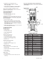
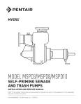
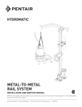
MODEL MGPD200 SUB POSITIVE DISPLACEMENT GRINDER PUMP INSTALLATION AND SERVICE MANUAL NOTE! To the installer: Please make sure you provide this manual to the owner of the equipment or to the responsible party who maintains the system. Part # 23833A569 | © 2013 Pentair Pump Group, Inc. | 08/22/13 GENERAL INFORMATION The power cord entry system is designed to give reliable sealing. The first seal is made by compression of a rubber gasket by the cord grip, thereby expanding to fill the cord entry of the motor housing. The cord grip forms a second seal around the molded cord end and provides strain relief. This manual contains important information for the safe use of this product. Read this manual completely before using this product and refer to it often for continued safe product use. DO NOT THROW AWAY OR LOSE THIS MANUAL. Keep it in a safe place so that you may refer to it often. Application: These pumps are designed for residential sewage discharge applications with a pH ranging from 5 to 9, specific gravities from 0.9 to 1.1, viscosities ranging from 28 to 35 S.S.U. and temperatures up to 140°F. Unpacking Pump: Remove pump from carton. When unpacking unit, check for concealed damage. Claims for damage must be made at the receiving end through the delivery carrier. Damage cannot be processed from the factory. Pump Not Operating or in Storage: Pumps with carbon ceramic seals must be manually rotated (6 revolutions) after setting nonoperational for 3 months or longer and prior to electrical start-up. PUMP CAUTIONS AND WARNINGS 1.WARNING: Before handling these pumps and controls, always disconnect the power first. Do not smoke or use sparkable electrical devices or flames in a septic (gaseous) or possible septic sump. Installing Pump in Sump: Before installing pump in sump, lay it on its side and rotate grinder shaft. Stator boot and rotor may be slightly stuck due to factory test water so it must be broken loose by rotating shaft with a screwdriver at the grinder end. The common shaft should turn with a slight resistance. Slight lubrication by means of a small amount of lubricating oil down the cavity inlet of the stator boot and rotating shaft to prelube stator boot and rotor before start is recommended. Do not connect the power until after this test. Clean all trash and sticks from sump and connect pump to piping. A check valve must be installed on each pump. 2.WARNING: Risk of Electrical Shock – This pump is supplied with a grounding conductor and grounding-type attachment plug. To reduce risk of electrical shock, be certain that it is connected only to a properly grounded, grounding-type receptacle. • Septic tank to be vented in accordance with local plumbing codes. • DO NOT remove cord or strain relief. DO NOT connect conduit to pump. Electrical installations shall be in accordance with the National Electrical Code and all applicable local codes and ordinances. • A septic sump condition may exist and if entry into sump is necessary, then (1) provide proper safety precautions per OSHA requirements and (2) do not enter sump until these precautions are strictly adhered to. • This pump has not been investigated for use in swimming pool areas. Location: If pumps are installed in an existing basin or concrete sump, the piping can either be connected permanently or rails and brackets can be furnished for mounting to walls of basin. In either case, be sure that the check valve is used and that the pumps are submerged in a vertical position. The complete factory built packaged system is recommended for the most satisfactory and economical installation. Making Electrical Connections: All electrical wiring must be in accordance with local code, and only qualified electricians should make the installation. All wires should be checked for shorts to ground with an ohmmeter or megger after the connections are made. This is important, as one grounded wire can cause considerable trouble. 3.Tank should be vented in accordance with local plumbing codes and should not be installed in locations classified as hazardous. 4.WARNING: Severe injury may result from accidental contact with moving cutters. Keep clothing, hands and feet away from cutters any time power is connected to the pump. PUMP OPERATIONS To start the pump, perform the following steps in order: CALIFORNIA PROPOSITION 65 WARNING: This product and related accessories contain chemicals known to the State of California to cause cancer, birth defects or other reproductive harm. 1.Grinder pump is single phase; no rotation check is necessary. 2.Run water into sump until motor is covered. PUMP INSTALLATION 3.Open gate valve in discharge line. The cutter blades are on the suction side of the positive displacement pump impeller and discharge directly into the inlet of the impeller. The integral stainless steel pump motor shaft is sealed by a single mechanical seal. 4.Turn pump on. If pump runs and sump liquid does not pump down, stop pump and close discharge gate valve. Lift pump until sealing flange is open to vent off trapped air. Lower pump, open discharge valve, and start the pump again. Two ball bearings are used to handle the loads in this design. The upper bearing takes radial loads, while the larger lower bearing handles both thrust and radial loads. Both bearings are permanently lubricated by the dielectric oil in the motor housing. The motor is fixed within the motor housing and is completely submerged in the dielectric oil for maximum heat transfer. The motor housing and seal chamber are completely sealed with O-rings located at mating part faces. 23833A569 11/08/12 CAUTION: Positive displacement pump is designed to operate at minimum 5 GPM capacity. Running pump at shut-off condition or with gate valve closed can result in damage to the pumping stator boot and rotor. 5.Level control should be set so that pump turns off when level is about 2 inches above inlet of pump suction and turns on when level is about 2 inches above motor. 2 If the cause of the trouble cannot be determined and corrected as outlined above, contact a factory authorized service facility. 6.If problems occur, check power source. Make sure a separate supply line is available. Verify voltage supply. 7.Check resistance of windings. If not within guidelines, return pump to authorized factory service center. 10 22 21 20 23 As the motors are oil filled, no lubrication or other maintenance is required. Pump should be checked every quarter for corrosion and wear. 14 10 PUMP MAINTENANCE 17 Inspecting Cutter Parts: 1.Close gate valve at pump discharge. 16 2.Turn off circuit breaker. CAUTION: Never work on pump with power on. Be sure ground wire from pump is connected to a good ground such as a water pipe. 11 13 3.Remove pump from sump. 4.Remove screws and stationary cutter ring assembly. Radial cutter can be screwed off the common shaft by lightly tapping cutter and unscrewing counterclockwise while holding end of common shaft with a screwdriver in slot at cutter end of shaft. 8 12 7 5.Radial cutter and stationary cutter can now be inspected for wear and replaced if necessary. 24 TROUBLESHOOTING 1 15 14 6 No liquid delivered 9 2 3 4 1.Pump air bound 2.Discharge head too high 5 18 19 3.Pump or piping plugged COMMON PARTS LIST 4.Speed too low Reference 1 2 3 4 5 6 7 8 9 10 11 12 13 14 15 16 17 18 19 20 21 22 23 24 Insufficient liquid delivered 1.Discharge head too high 2.Cutter partially plugged or damaged 3.Stator boot or rotor damaged or worn 4.Speed too low Insufficient discharge pressure 1.Air or gases in liquid 2.Stator boot or rotor damaged or worn 3.Speed too low Pump overloads motor 1.Specific gravity or viscosity of liquid too high 2.Speed too high 3.Head lower than rating, pumping too much liquid 4.Pump clogged 5.Defective bearings Pump is noisy 1.Defective bearings 2.No diametrical clearance between radial cutter and cutter ring 3 Part Number 146240002 145690012 21582B000 21584B000 19099A023 001800021 008340231 146270001 008920071 25338B001 001010081 001780061 000770111 147621011 145730001 145701001 25327D000 148850001 055700051 05030A234 05014A193 05030A235 145870001 147610001 Description CASE – VOLUTE HOUSING – SEAL/BEARING CUTTER – RADIAL CUTTER – STATIONARY SCREW – CAP PIN – ROLL, LOWER O-RING RING – RETAINER SCREW – RING RETAINER CORD – POWER SCREW – CAP SCREW – SOCKET O-RING ROTOR – HELIX SEAL – SHAFT MOTOR HOUSING – MOTOR SCREW – SHAFT, MOTOR WASHER – SHAFT IMPELLER WASHER – SST 1/32 THICK GASKET – RUBBER WASHER – SST 3/32 THICK NUT – CORD STATOR – PUMP Qty. 1 1 1 1 3 1 1 1 3 1 4 4 1 1 2 1 1 1 1 1 1 1 1 1 23833A569 11/08/12 STANDARD LIMITED WARRANTY Pentair Myers® warrants its products against defects in material and workmanship for a period of 12 months from the date of shipment from Pentair Myers or 18 months from the manufacturing date, whichever occurs first – provided that such products are used in compliance with the requirements of the Pentair Myers catalog and technical manuals for use in pumping raw sewage, municipal wastewater or similar, abrasive-free, noncorrosive liquids. During the warranty period and subject to the conditions set forth, Pentair Myers, at its discretion, will repair or replace to the original user, the parts that prove defective in materials and workmanship. Pentair Myers reserves the right to change or improve its products or any portions thereof without being obligated to provide such a change or improvement for prior sold and/or shipped units. Start-up reports and electrical schematics may be required to support warranty claims. Submit at the time of startup through the Pentair Myers website: http://forms.pentairliterature.com/startupform/startupform.asp?type=m. Warranty is effective only if Pentair Myers authorized control panels are used. All seal fail and heat sensing devices must be hooked up, functional and monitored or this warranty will be void. Pentair Myers will cover only the lower seal and labor thereof for all dual seal pumps. Under no circumstance will Pentair Myers be responsible for the cost of field labor, travel expenses, rented equipment, removal/reinstallation costs or freight expenses to and from the factory or an authorized Pentair Myers service facility. This limited warranty will not apply: (a) to defects or malfunctions resulting from failure to properly install, operate or maintain the unit in accordance with the printed instructions provided; (b) to failures resulting from abuse, accident or negligence; (c) to normal maintenance services and parts used in connection with such service; (d) to units that are not installed in accordance with applicable local codes, ordinances and good trade practices; (e) if the unit is moved from its original installation location; (f) if unit is used for purposes other than for what it is designed and manufactured; (g) to any unit that has been repaired or altered by anyone other than Pentair Myers or an authorized Pentair Myers service provider; (h) to any unit that has been repaired using non factory specified/OEM parts. Warranty Exclusions: Pentair MYERS MAKES NO EXPRESS OR IMPLIED WARRANTIES THAT EXTEND BEYOND THE DESCRIPTION ON THE FACE HEREOF. Pentair MYERS SPECIFICALLY DISCLAIMS THE IMPLIED WARRANTIES OF MERCHANTABILITY AND FITNESS FOR ANY PARTICULAR PURPOSE. Liability Limitation: IN NO EVENT SHALL Pentair MYERS BE LIABLE OR RESPONSIBLE FOR CONSEQUENTIAL, INCIDENTAL OR SPECIAL DAMAGES RESULTING FROM OR RELATED IN ANY MANNER TO ANY Pentair MYERS PRODUCT OR PARTS THEREOF. PERSONAL INJURY AND/OR PROPERTY DAMAGE MAY RESULT FROM IMPROPER INSTALLATION. Pentair MYERS DISCLAIMS ALL LIABILITY, INCLUDING LIABILITY UNDER THIS WARRANTY, FOR IMPROPER INSTALLATION. Pentair MYERS RECOMMENDS INSTALLATION BY PROFESSIONALS. Some states do not permit some or all of the above warranty limitations or the exclusion or limitation of incidental or consequential damages and therefore such limitations may not apply to you. No warranties or representations at any time made by any representatives of Pentair Myers shall vary or expand the provision hereof. 1101 MYERS PARKWAY 490 Pinebush Road, Unit #4 ASHLAND, OHIO, USA 44805 CAMBRIDGE, ONTARIO, CANADA N1T 0A5 419-289-1144800-363-PUMP WWW.FEMYERS.COM Warranty Rev. 12/13