1
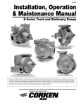
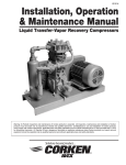
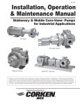
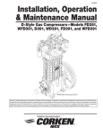
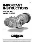
ID107D
Installation, Operation
& Maintenance Manual
PZ-Series Coro-Vane® Petroleum Pump
For Refined Petroleum Products and Industrial Solvents
PZ7 Model with Standard Bypass Valve
Warning: (1) Periodic inspection and maintenance of Corken products is essential. (2) Inspection, maintenance and installation of Corken
products must be made only by experienced, trained and qualified personnel. (3) Maintenance, use and installation of Corken products must
comply with Corken instructions, applicable laws and safety standards (such as NFPA Pamphlet 58 for LP-Gas and ANSI K61.1-1972 for
Anhydrous Ammonia). (4) Transfer of toxic, dangerous, flammable or explosive substances using Corken products is at user’s risk and
equipment should be operated only by qualified personnel according to applicable laws and safety standards.
Warning
Install, use and maintain this equipment according to Corken’s instructions and all applicable federal, state, local laws and
codes. Periodic inspection and maintenance is essential.
Corken One Year Limited Warranty
Corken, Inc. warrants that its products will be free from defects in material and workmanship for a period of 12 months
following date of purchase from Corken. Corken products which fail within the warranty period due to defects in material
or workmanship will be repaired or replaced at Corken’s option, when returned, freight prepaid to CORKEN, INC., 3805
N.W. 36th Street, Oklahoma City, Oklahoma 73112.
Parts subject to wear or abuse, such as mechanical seals, vanes, piston rings, packing and other parts showing signs of
abuse are not covered by this limited warranty. Also, equipment, parts and accessories not manufactured by Corken but
furnished with Corken products are not covered by this limited warranty and purchaser must look to the original
manufacturer’s warranty, if any. This limited warranty is void if the Corken product has been altered or repaired without the
consent of Corken.
All implied warranties, including any implied warranty of merchantability or fitness for a particular purpose, are expressly
negated to the extent permitted by law and shall in no event extend beyond the expressed warranty period.
Corken disclaims any liability for consequential damages due to breach of any written or implied warranty on Corken
products. Transfer of toxic, dangerous, flammable or explosive substances using Corken products is at the user’s risk.
Such substances should be handled by experienced, trained personnel in compliance with governmental and industrial
safety standards.
Contacting the Factory
Before you contact the factory, note the model number and serial number of your pump. The serial number directs us to
a file containing all information on material specifications and test data applying to your specific pump. When ordering
parts, the Corken service manual or IOM (Installation, Operations and Maintenance) manual should be consulted for the
proper part numbers. ALWAYS INCLUDE THE MODEL NUMBER AND SERIAL NUMBER WHEN ORDERING PARTS.
The model and serial numbers are shown on the nameplate of the unit. Record this information for future reference.
Model no. _______________________________________________________________________________________
Serial no. ________________________________________________________________________________________
Date purchased ___________________________________________________________________________________
Date installed _____________________________________________________________________________________
Purchased from ___________________________________________________________________________________
Installed by _______________________________________________________________________________________
2
Table of Contents
Principles of the PZ-Series Pump ................................................................................................................................... 4
Exclusive Features of PZ-Series Pump .......................................................................................................................... 4
Installation of the PZ-Series Pump ................................................................................................................................. 4
Operation of the PZ-Series Truck Pump ......................................................................................................................... 5
Maintenance of Your Pump System ................................................................................................................................ 6
Pump Maintenance Schedule ...................................................................................................................................... 6
Disassembly and Assembly Instructions for the PZ-Series Pump ................................................................................... 6
Disassembly Instructions ............................................................................................................................................. 6
Assembly Instructions ................................................................................................................................................. 7
Mechanical Seal and Vane Replacement Instructions .................................................................................................... 8
Cleanliness and Workmanship .................................................................................................................................... 8
Lubrication ................................................................................................................................................................... 9
Repair Kits for the PZ-Series ........................................................................................................................................ 10
Appendix A—Model Number and Indentification Code ................................................................................................. 11
Appendix B—Technical Specifications .......................................................................................................................... 12
Appendix C—Performance Curves ............................................................................................................................... 13
Appendix D—Outline Dimensions for the PZ7 .............................................................................................................. 15
Appendix D—Outline Dimensions for the PZ10 ............................................................................................................ 16
Appendix D—Outline Dimensions for the Air Operated Valve (AOV) and Strainer ........................................................ 17
Appendix E—Parts Details for the PZ7 with the Standard Bypass Valve ....................................................................... 18
Appendix E—Parts Details for the PZ10 with the Standard Bypass Valve ..................................................................... 19
Appendix E—Parts Details for the PZ7 Air Operated Valve (AOV) ................................................................................ 20
Appendix E—Parts Details for the PZ10 Air Operated Valve (AOV) .............................................................................. 21
Appendix E—Parts Details for the Strainer ................................................................................................................... 22
Appendix F—Trouble Shooting Guide for the PZ-Series Pump .................................................................................... 23
Appendix G—Flush and Storage Instructions for the PZ-Series Pump ......................................................................... 24
3
Principles of the PZ-Series Pump
The PTO SELECTION is important. The pump requires a
PTO with an average output speed of 500 to 700 RPM for
maximum performance when the truck engine is operating at
the proper speed to maintain oil pressure and water circulation.
The PZ-Series pump is a special type of rotary positive
displacement pump, known as a sliding vane pump.
THE DRIVESHAFT connecting the pump to the PTO should
be of the “splined” or slip type. This type driveshaft permits
the shaft to adjust for PTO movement and twisting of the
truck frame. A fixed driveshaft transfers the forces directly
into the pump and PTO and will shorten the life of both
considerably. The yokes of the driveshaft universal joints
must be positioned as shown on page 5, Figure 1. Improper
positioning will soon wear them out and potentially destroy
the bearings in the pump and PTO.
The sliding vane pump has many of the positive
displacement advantages of the gear pump, plus the ability
to compensate for wear, and operate at a lower noise level.
The sliding vane pump consists of a rotor turning in a cam
machined eccentrically in relation to the rotor; thereby
displacing the liquid trapped between the rotor, cam and
vanes. The PZ-Series pumps are made with vanes produced
from advanced polymers which exhibit extremely low
coefficients of friction. The vanes are self-adjusting for wear
which gives the pump long life.
INLET PIPING should be as short as possible and at least
the minimum diameter specified for the model with minimum
restrictions so that the pressure drop is limited.
Exclusive Features of the
PZ-Series Pump
The outlet piping should include the following:
1. A pressure gauge should be installed in the pump outlet
or near it. A pressure gauge is necessary to determine
the efficiency of your pumping system.
The pumping of volatile liquids is one of the most difficult of
all pumping jobs, and pumping from a delivery truck makes
it even more difficult, so more attention must be given to the
design and manufacturing of the pump and to its installation
and operation.
2. If a meter with an air eliminator is installed, never pipe
the eliminator directly into the pump inlet piping or into
the liquid part of the system at any point (refer to the
meter installation manual).
In addition to being especially suited for handling volatile
liquids, your PZ-Series pump has a number of features to
help make it more easily operated and maintained.
3. The discharge piping should be at least the same size as
the meter piping.
The CASE and HEADS are made of Ductile Iron, not Cast
Iron, for extra strength and toughness.
Power Take-Off Drive Systems
Proper pump operation and long life is directly dependent
upon a good drive system. Many truck pumps utilize a power
train consisting of shafts and universal joints from a power
take-off shaft on the truck engine to the pump.
The VANES are manufactured of advanced polymers to
provide excellent life and quiet operation. After long service,
the vanes are simply and inexpensively replaced.
SIDEPLATES may be reversed for extended service life.
The sideplates are easily replaced should the need arise.
There are several basic principles that should be followed
in laying out a PTO drive. These principles should not be
violated to produce a workable power train that results in
long pump life and reduced drive wear.
THE MECHANICAL SEAL is designed for longer life under
greater loads and may be inspected or replaced without
disturbing the piping of the pump. No special tools are needed.
First, the driver shaft and the driven shaft must be parallel
to one another within plus or minus one degree. Improper
alignment will cause jerking and back and forth “whip” to
the pump shaft, thereby imparting a surging pulsation to the
liquid flow, which results in noise, vibration and abnormal wear.
BEARINGS are heavy-duty roller type for long bearing life.
THRUST BEARINGS are heavy-duty needle roller type rated
for 4,000 lbs.
Second, the angle of the ‘’floating’’ shaft should be within
the limits for the particular equipment being used (usually a
maximum of 15° at pump speeds up to 800 RPM). To ensure
that shaft expansion or contraction does not distort the drive
system, a splined slip joint should be placed between the
two universal joints. The drive shaft should be of the “splined”
or slip type to permit the shaft to adjust for PTO movement
and twisting of the truck frame. A fixed drive shaft transmits
the forces directly to the pump and PTO which will shorten
the life of both considerably.
NONMETALLIC VANE DRIVERS do not penetrate the
vanes like the conventional steel vane drivers.
Available with adjustable internal BYPASS VALVE or optional
AIR OPERATED VALVE (AOV) for high and low flow control.
Installation of the PZ-Series Pump
The mechanical installation of the PZ-Series pump is a
simple matter. A rotation arrow is located on the side of the
pump so check the PTO to determine its direction of rotation.
The PZ-Series pump will match either PTO rotation. Connect
the drive shaft to the pump shaft that turns the pump in the
direction of the arrow.
Third, the yokes of the drive shaft universal joints must be
in a parallel position. Figure 1 on page 5 illustrates the proper
arrangement of the yokes.
4
Improper installation of the U-joints will soon destroy them
along with the bearings in the pump and PTO. Properly
mounted, the second universal gives uniform motion to the
drive shaft by compensating for the rotational error
introduced by the first U-joint. An even number of universal
joints (2, 4, 6 etc.) should always be used. An odd number
of U-joints will cause unbalanced pump shaft rotation. This
problem becomes greater with increased angularity.
3. Check the discharge pressure on the outlet of the pump.
This pressure is typically set at 80 to 95 psi.
4. Standard Bypass Valve
For a standard bypass valve, locate the adjustment set
screw under the adjustment set screw cap (see parts
details on pages 18 and 19). Turn adjustment screw
clockwise to increase pressure and flow. Turn counter
clockwise to decrease pressure and flow.
Other points to consider include the proper sizing of the
shaft components with a maximum horsepower load to be
expected, good alignment of hanger bearings and proper
pump coupling alignment.
Close nozzle and check bypass pressure. If too high, turn
adjustment screw counter clockwise until desired
pressure is reached.
Improper PTO systems account for a high percentage of
truck pump failures. Always remember to disengage the
clutch before shifting the PTO into gear. Shifting the PTO
into gear without disengaging the clutch imparts an
enormous shock on the PTO, drive shaft, pump and meter
and will soon damage one or all of them.
With the hose nozzle open, adjust the pump bypass valve
setting to the desired flow rate. Close the nozzle slowly
and check the system pressure. CAUTION: DO NOT
EXCEED A CLOSED NOZZLE PRESSURE OF 125 PSI.
Replace adjustment set screw cap with seal washer
and tighten.
For proper installation of pump drives, follow the rules
listed below:
5. Air Operated Valve (AOV) assembly
For pumps equipped with an Air Operated Valve (AOV)
assembly, air must be supplied from the truck air system
via a flow sensing valve. Approximately 70 psi (4.8 bar)
minimum air pressure is required to properly operate the
air operated valve. THE AIR PRESSURE MUST NOT
EXCEED 125 psi (8.6 bar). The sensing valve should be
installed in accordance with the diagram shown in
Figure 2. This system depicts the additional use of a
throttle control which is optional. All adjustments must be
made at normal operating speeds.
1. Driver shaft and pump shaft must be parallel, plus or
minus one degree.
2. Operating angle of the ‘’floating’’ shaft must be 15° maximum.
3. Universal yokes must be in line and parallel.
4. Splined slip joints must be used where needed.
5. Use an even number of universal joints.
6. Always use the least practical number of shafts.
5.1
Set the low pressure adjustment first by slowly
closing the nozzle to relieve the air pressure in the
AOV assembly.
5.2
Remove the adjustment stem cap and O-ring (see
parts details on pages 20 and 21).
Figure 1, Shaft alignment
PTO selection and drive system design is extremely
important. The PTO should have an average output speed
up to 800 RPM to maximize the performance of the PZSeries pump when the truck engine is operating at the
recommended speed.
The designer of the drive system must select a PTO drive
shaft capable of meeting the torque requirements of the
pumping system.
Operation of the PZ-Series Pump
Truck Pump
The following steps should be performed for the initial
pumping operation:
1. Close the shutoff valve on the end of the delivery hose.
2. Start the pump and cycle the nozzle open and closed to
clear all air from the system.
Figure 2, Typical truck delivery system using an AOV.
5
5.3
Turn the low pressure adjustment bushing counterclockwise to decrease the bypass pressure and
vice versa to increase the pressure (see parts
details on pages 20 and 21).
5.4
Re-install the O-ring and adjustment stem cap and
tighten securely.
5.5
Open and close the nozzle several times to ensure
proper setting and repeatablility.
5.6
Slowly close the delivery nozzle again to relieve
the air pressure in the AOV assembly.
5.7
Remove the adjustment stem cap and O-ring.
5.8
Adjust the locknuts clockwise to decrease delivery
flow rate and/or pressure and vice versa to increase
the flow rate. NOTE: Make sure the locknuts
are securely locked against each other
before re-installing the adjustment stem
cap and O-ring.
5.9
Bearing Lubrication
There are two lubrication points in which to grease the pump
bearings; one zerk per bearing cap located at opposite ends
of the pump. Four grease relief and seal ventilation fittings
have been provided, two at each end of the pump, to help
prevent over greasing the bearings. Over greasing can
cause seal failure if grease passageways are blocked in
some way. Remove relief fittings or confirm free movement
of relief prior to greasing bearings. Clean each fitting before
lubricating the bearings. This practice helps to prevent foreign
material contamination of the bearings and accidental overpressurization of the mechanical seals. Use only Ball Bearing
Grease (MIL-G-10924C) with a temperature rating of -70°F.
Normal wear parts are the mechanical shaft seals,
bearings, vanes, vane drivers and sideplates. All of these
parts plus O-rings and grease seals are offered in the
“repair kit.” Use only genuine Corken replacement parts
when repairing your PZ-Series pump. Follow the
instructions provided with the parts.
Slowly open the delivery nozzle and note delivery
flow rate and/or pressure.
When it becomes necessary to repair your pump or remove
it from the system, you must be absolutely certain that all
product being pumped is bled from the pump and connected
piping. Once all the product has safely been bled from the
pump and connected piping, make certain no pressure is
left in the system. SPECIAL CARE MUST BE TAKEN
DURING THE BLEED DOWN PROCESS TO AVOID
DANGER TO PERSONNEL AND PROPERTY IN THE
AREA. Take your time in bleeding your system and make
proper provisions to vent or capture the product in
accordance with local regulations. ONLY A PROPERLY
TRAINED INDIVIDUAL SHOULD BE ALLOWED TO BLEED
A PUMPING SYSTEM.
5.10 Repeat steps 5.7 through 5.9 until desired flow
rate and/or pressure are achieved.
6. You may increase the speed of the pump as long as it
increases the flow through the delivery nozzle. It is
recommended to turn the pump at approximately 575
RPM for optimum performance. However, the pump can
be safely turned to 800 RPM if system conditions permit.
NOTE: IF PUMP SPEED IS INCREASED, BE CERTAIN
THE METER AND PIPING SYSTEM WILL HANDLE THE
INCREASED FLOW AND PRESSURE!
Maintenance of Your Pump System
Disassembly and Assembly
Instructions for the PZ-Series Pump
Your PZ-Series pump requires regular maintenance and
care like all mechanical equipment. A neglected or
improperly repaired pump will result in premature failure and
cause unsafe conditions. To promote product longevity and
safety, maintenance must be performed by properly trained
technicians. Make sure all safety systems are in place and
the system pressure has been relieved before attempting
ANY maintenance.
Disassembly Instructions
1. Truck engine must be turned off and PTO disengaged.
2. Bleed all product from the system as described above.
NOTE: There is a 1/4" NPT connection in the bottom of
the pump case that allows you to easily drain the pump.
Pump Maintenance Schedule
3. Remove the PTO shaft or hydraulic drive motor, adapter,
and coupling.
Make sure the transfer hoses are not “kinked’’. A kinked
hose can cause excessive pump discharge pressure. Always
make sure your hoses are not out of date.
Daily
Lubricate bearings
Monthly
4. Remove the eight 7/16" head bolts from one head.
5. Slide head assembly off pump shaft ensuring the pump
rotor-shaft remains in the pump.
3 Months
6. Inspect the mechanical seal carbon face for scoring or
pitting and discard if damaged. Ensure the rotor-shaft
remains inside pump. NOTE: If rotor is pulled with head,
it will disengage the seal assembly on the opposite side.
•
Inspect drive coupling
•
Clean Inlet Strainer
•
Check for leaks
•
Inspect hose and fittings
•
7. If the mechanical seal requires replacement, slide a
screwdriver through the head assembly from the bearing
cap and tap the stationary seal face out.
6
8. Remove the four 3/8" bolts from the bearing cap to gain
access to the thrust bearing. Retain the bearing cap
shims independently for each side of the pump. Inspect
the thrust washers and needle roller assembly for scoring
or pitting. Discard if damage found. Retain mounting ring
for future use.
Remove and discard the gasket and clean the gasket
areas. Remove the two recessed-head machine screws
and the diaphragm cover plate. Slide the diaphragm
assembly out from the housing. Remove the vent plate
from between the two diaphragms. Inspect the
diaphragms, spring, and valve for abrasions and replace
if necessary.
9. Remove the spiral snap ring in the pump head to facilitate
removal of the main bearing. Inspect the bearing rollers
and inner race for scoring or pitting. Replace if damage
is found. Retain the snap ring for future use. The main
bearing can be easily removed by inserting a screwdriver
through the head from the mechanical seal side and
lightly tapping. Work the screwdriver around the inside
perimeter of the bearing as the bearing is lightly pressed
into the head.
Assembly Instructions
1. Place three vanes into the upper three rotor-shaft slots.
Ensure the curved tip of each blade faces radially outward
and all in the same direction of rotation.
2. While cupping these vanes in place, rotate the rotorshaft over 180° and install the three blade drivers.
3. Place rotor-shaft and blade assembly into pump case
with the three vanes on the bottom. Ensure the ribs in
the vanes face into the direction of rotation of the pump
(see parts details on pages 18 and 19).
10. Inspect inner grease seal and head O-ring for cuts or
abrasions and remove and change if necessary.
11. Inspect the outer grease seal in the bearing cap for cuts
or abrasions and remove if necessary.
4. Place the remaining three vanes into the upper rotor-shaft
slots facing the same direction as the first three vanes.
12. Repeat steps 3 through 10 for remaining head assembly.
5. Install both sideplates into the pump simultaneously to
keep the rotor-shaft level and centered in the pump case.
Rotate each sideplate until the square notch is in the
twelve o’clock position. Rotate the rotor-shaft to expose
the seal drive pins.
13. Using a bearing cap or flange bolt (3/8"), slide the
sideplate off of the rotor-shaft while holding other end of
rotor-shaft in place. Once removed, the rotor-shaft can
be pulled slightly toward the remaining sideplate and
allowed to rest within the pump case. Inspect the
sideplates for wear. If sideplates are worn on both sides,
discard for replacement.
6. Install the mechanical seal assemblies onto each end
of the rotor-shaft. Ensure the seal drive pin properly
engages the mechanical seal retainer detent. Lightly oil
each carbon seal face.
14. Carefully remove the rotor-shaft assembly with the vanes
and drivers by cupping the lower vanes in place. Inspect
vanes and drivers for wear or abrasions. Replace if
damage is found.
7. Press the inner grease seals into each head with the
cup opening toward the mechanical seal.
15. Inspect the rotor O.D. and cam inner surface for scoring
or pitting. Should the condition arise, the pump should
be completely replaced if severe scoring of the cam inner
surface is discovered.
8. Press the main bearings into each head and install the
spiral retainer ring.
9. Install the stationary seal face by applying a light oil — DO
NOT use WATER based penetrants —and pressing into
place with the protective cardboard disc and your fingers.
Apply another coat of light oil to the face to remove any
debris from installation.
16. If you have the standard bypass valve, remove
the bypass valve adjustment screw cap and turn the
adjustment screw counterclockwise to relieve the spring
tension. Remove the four 3/8" bolts from the bypass
valve cap. Use caution as a small amount of spring
tension will remain on the bypass valve spring
before complete bolt removal. Inspect bypass valve,
spring, and bypass valve cap O-ring for wear, abrasions,
etc. Replace if damage is found.
10. Install the head O-ring and lubricate with light oil.
11. Carefully slide the first head assembly over the rotorshaft ensuring the rotor-shaft remains within the pump
case. Install the eight 5/8" hex head bolts and torque in
a crossing pattern to 45 ft•lb. Repeat for remaining
head assembly.
17. If you have an Air Operated Valve (AOV), ensure
the air supply pressure has been relieved and the supply
line disconnected from the valve housing. Remove the
outer cap and discard the O-ring from underneath.
Remove the retainer ring and locknuts from the
adjustment stem. Remove the four 3/8" bolts and lock
washers from the bypass valve housing. Use caution
as a small amount of spring tension may remain on
the bypass valve spring. Carefully remove the AOV
assembly from the pump along with the spring and valve.
12. Install thrust bearing assemblies onto each mounting
ring and place over each end of the rotor-shaft. Ensure
the needle roller assemblies are sandwiched between
the thrust washers and their orientation is facing outward
from the pump.
13. Press each outer grease seal into each bearing cap.
7
14. Place one bearing cap over the end of the rotor-shaft
and bolt in place finger tight. Grasp the rotor-shaft and
ensure it does not turn by hand. Measure the gap
between the head and bearing cap. Remove the bearing
cap and install the measured amount of shims plus .006"
(yellow shims are .020", brown shims are .010", and red
shims are .002"). Round up if necessary. Install bearing
cap with four 3/8" x 1 ½" bolts and lock washers and
torque to 25 ft•lb.
2. Remove the PTO shaft or hydraulic drive motor, adapter,
and coupling.
3. Remove the eight 5/8" hex head bolts from one head.
15. Place the remaining bearing cap over the other end and
again tighten the four bolts finger tight. Again, measure
the gap between the head and the bearing cap and remove
the bearing cap. Install the measured amount of shims
plus .002" and install bearing cap as described above.
16. Ensure the pump rotates smoothly without binding. If
binding occurs repeat steps 14 and 15.
17. If you have a standard bypass valve, install the
O-ring into the O-ring groove in the bypass valve cap
and lubricate using light oil. Install the valve, spring,
guide, and cap on the pump with the four 3/8" bolts and
torque to 15 ft•lbs.
4. Slide one head assembly off the pump shaft ensuring
the pump rotor-shaft remains in the pump.
5. Remove the mechanical seal carbon face assembly
while pressing against the sideplate ensuring the rotorshaft remains within the pump case.
18. If you have an Air Operated Valve (AOV) assembly,
install the vent plate between the two diaphragms ensuring
proper orientation with the screw holes in the housing.
Slide the diaphragm assembly into the housing and install
the diaphragm cover plate and recessed-head machine
screws and tighten securely. Install this assembly with the
valve, spring, and gasket to the pump using the four 3/8"
bolts and lock washers and torque to 15 ft•lbs. Install both
locknuts all the way down the adjustment stem and replace
the retainer ring. Install the new O-ring and outer
adjustment stem cap. Refer to Operation of the PZ Series
Truck Pump on page 5 for adjustment procedure.
19. Grease bearings per the instructions listed on page 6
under Pump Maintenance Schedule.
20. Install the pump according to the installation guidelines
mentioned previously on page 4.
6. Remove the inner grease seal and stationary face by
inserting a screwdriver through the head assembly from
the bearing cap and tapping the grease seal and
stationary face out.
Mechanical Seal and Vane
Replacement Instructions
Cleanliness and Workmanship
Even the smallest amount of dirt on your new seal can cause
early failure. Keep all parts, tools and your hands clean while
installing the seal. Never touch the smooth lapped faces of
the carbon rotor or seal seat.
Lastly, your Corken pump is a precision piece of equipment
with very close clearances. Treat it as such. Never use force
during assembly or disassembly.
1. CAUTION: Bleed all pressure and product from the pump
and piping before installing your new seal assembly.
8
7. Using the old seal stationary face, press a new inner
grease seal in place ensuring the seal cup faces toward
the mechanical seal. This can be accomplished with a
hammer and drift.
17. Install the mechanical seal assemblies onto each end
of the rotor-shaft. Ensure the seal drive pin properly
engages the mechanical seal retainer detent. Lightly oil
each carbon seal face.
8. Apply a light oil to the new stationary seal face O-ring
and press in with your fingers ensuring the grooved side
faces the main bearing.
18. Lubricate the head O-ring and roll into place on the head.
9. Repeat steps 3 through 8 for the remaining head assembly.
If vane replacement is necessary follow steps 10 through
16. If not proceed to step 17.
10. Using a bearing cap or flange bolt (3/8"), slide one
sideplate off of the rotor-shaft while holding other end of
rotor-shaft in place. Once removed, the rotor-shaft can
be pulled slightly toward the remaining sideplate and
allowed to rest within the pump case. Inspect the
sideplates for wear. If sideplates are worn on both sides,
discard for replacement.
11. Remove the rotor-shaft assembly from the pump case
by cupping the bottom three vanes with your hand. This
will not allow the vanes and drivers to fall from the rotorshaft slots.
19. Install each head by supporting the back end of the rotorshaft and working the head into place over the rotor-shaft.
12. Place three vanes into the upper three rotor-shaft slots.
Ensure the curved tip of each vane faces radially outward.
21. Grease bearings per instructions listed on page 6 under
Pump Maintenance Schedule and the instructions
listed below.
13. While cupping these vanes in place, rotate the rotorshaft over 180° and install the vane drivers.
Lubrication
14. Place rotor-shaft and blade assembly into pump case
with the three vanes on the bottom. Ensure the ribs in
the vanes face into the direction of rotation of the pump.
Regrease the bearing after thoroughly cleaning the grease
opening and fittings. If dirt is forced into the bearings, early
failure will result.
15. Place the remaining three vanes into the upper rotor-shaft
slots facing the same direction as the first three vanes.
Special relief fittings have been provided to help prevent
over-greasing the bearings. Excessive grease may drip out
after lubrication. Over-greasing can damage the pump
bearings and cause seal leaks.
20. Install the head bolts and torque to 45 ft•lb.
16. Install both sideplates into the pump simultaneously to
keep the rotor-shaft level and centered in the pump case.
Rotate each sideplate until the square notch is in the
twelve o’clock position. Rotate the rotor-shaft to expose
the seal drive pins.
Use only recommended ball bearing grease. If you use a
hand grease gun, put the grease in slowly and stop as soon
as the relief fitting opens.
Grease the U-joints and the spline of the drive shaft when
greasing the pump.
9
Repair Kits for the PZ-Series
PZ7 Repair Kit 5497-X1A (Buna-N)
Part Number
Description
Qty.
Part Number
Description
1480
Gasket
1
1480
Gasket
2-142A
O-ring, Buna-N
2-234A
O-ring, Buna-N
2270
2754-X
1
2-142D
Qty.
1
O-ring, Viton®
1
1
1
2
2
2-234D
O-ring, Viton®
Shaft key
1
2270
Shaft key
1
Roller bearing
2
2754-X
Roller bearing
2
4262-X
Vane driver
3
4262-X
Vane driver
3
4431-XA2
Seal assembly, Buna-N
2
4431-XD2
Seal assembly, Viton® 1
2
4432
Thrust bearing
2
4432
Thrust bearing
2
4435
Thrust bearing mounting ring
2
4435
Thrust bearing mounting ring
2
4439
Bearing cap shim (0.002")
8
4439
Bearing cap shim (0.002")
8
4439-1
Bearing cap shim (0.010")
2
4439-1
Bearing cap shim (0.010")
2
4439-2
Bearing cap shim (0.020")
2
4439-2
Bearing cap shim (0.020")
2
4441
Grease seal
2
4441
Grease seal
2
5372
Vane
6
5372
Vane
6
PZ10 Repair Kit 5498-X1A (Buna-N)
1
PZ7 Repair Kit 5497-X1D (Viton®1)
PZ10 Repair Kit 5498-X1D (Viton®1)
Part Number
Description
Qty.
Part Number
Description
1480
Gasket
1
1480
Gasket
2-234A
O-ring, Buna-N
2270
2754-X
Qty.
1
1
3
2-234D
O-ring, Viton®
Shaft key
1
2270
Shaft key
1
Roller bearing
2
2754-X
Roller bearing
2
4262-X
Vane driver
5
4262-X
Vane driver
5
4431-XA2
Seal assembly, Buna-N
2
4431-XD2
Seal assembly, Viton® 1
2
4432
Thrust bearing
2
4432
Thrust bearing
2
4435
Thrust bearing mounting ring
2
4435
Thrust bearing mounting ring
2
4439
Bearing cap shim (0.002")
8
4439
Bearing cap shim (0.002")
8
4439-1
Bearing cap shim (0.010")
2
4439-1
Bearing cap shim (0.010")
2
4439-2
Bearing cap shim (0.020")
2
4439-2
Bearing cap shim (0.020")
2
4441
Grease seal
2
4441
Grease seal
2
5365
Vane
6
5365
Vane
6
Viton® is a registered trademark of the Dupont company.
10
3
Appendix A— Model Number and Identification Code for PZ-Series
Model Number
Base X X X X X X X
Base Model
Basic pump
Model PZ7 or PZ10
Standard
PZ7
No strainer
Standard
N
Strainer
Optional
S
Standard valve
Standard
S
Air Operated Valve
Optional
A
Low (50–75 psi)
Optional
1
Std. (75–100 psi)
Standard
2
High (100–125 psi)
Optional
3
Viton® 2
Standard
D
Buna-N
Optional
A
Stainless steel
Optional
1
Cast iron
Standard
2
Ni-Resist
Optional
3
Specification Fields
Strainer1
Internal bypass
valve
Bypass valve
spring
Seal O-ring
material
Seal seat
material
1
Strainer is attached to the pump when specified by suffix “S” in the configurated
string. When the strainer is required separate from the pump, order using the Part
Number found in the Strainer Assembly table on page 12.
2
Viton® is a registered trademark of the Dupont company.
Inlet Flange Options
Standard
Optional
2" NPT
E
2-1/2" NPT
J
2" BSPT
M
2-1/2" BSPT
N
2" Weld
F
2-1/2" Weld
K
2" NPT
E
2-1/2" NPT
J
2" BSPT
M
2-1/2" BSPT
N
Outlet Flange Options
Standard
Optional
2" Weld
F
2-1/2" Weld
K
11
Appendix A—Model Number and Identification Code for Strainer and Air
Operated Valve (AOV)
Strainer Assembly1
Strainer assembly
1
2
Seal Material
Strainer Assy. Part Number
Viton® 2 (standard)
5422-XD
Buna-N (optional)
5422-XA
Strainer Assembly ordered by Part Number when not assembled to the pump.
Viton® is a registered trademark of the Dupont company.
Air Operated Valve Assembly (AOV)
For Pump Models
AOV Part Number
PZ7
5470-X
PZ10
5462-X
Air Operated Valve
(AOV)
Appendix B—Technical Specifications for PZ7 and PZ10
Operating Specifications
Standard connections:
2" or 2-1/2" NPT
Optional connections:
2" or 2-1/2" Slip-on weld, BSPT
Maximum differential pressure:
125 psid (8.6 bar)
Operating temperature range:
Up to 300°F (149°C)
Maximum working pressure:
200 psi (13.8 bar)
Maximum speed:
800 RPM
Fluids:
For refined petroleum products
and industrial solvents
Material Specifications
Part
Material
Case
All
Ductile iron ASTM A536
Head
All
Ductile iron ASTM A536
Flanges
All
Ductile iron ASTM A536
Rotor
All
Ductile iron ASTM A536
Bearing cap
All
Ductile iron ASTM A536
Sideplates
All
Cast iron Class 30
Vanes & vane drivers
All
Advanced polymer
By-pass valve
All
17- 4 PH Stainless steel
By-pass spring
All
Steel
Seal seat
All
Cast iron (standard), Stainless steel and Ni-Resist (optional)
Seal metal parts
All
Steel
Shaft
All
8620 steel
Thrust bearing
All
O-rings
1
Model
Steel
1
All
Viton® (standard), Buna-N (optional)
Viton® is a registered trademark of the Dupont Company
12
Appendix C—Performance Curves1
PZ7 Truck Pump
120
110
800 RPM
Capacity (gpm)
100
90
640 RPM
80
70
575 RPM
420 RPM
60
50
40
25
0
50
75
125
100
Differential Pressure (psi)
Pump Speed
RPM
Differential Pressure
psi
bar
Nominal Flowrate
Brake HP Required
Torque Required
gpm
L/min
bhp
kW
in•lbs
N•m
800
90
6.2
98
371
6.8
5.0
536
60.5
800
50
3.4
105
397
3.8
2.2
299
33.8
640
90
6.2
78
295
5.5
4.1
542
61.2
640
50
3.4
84
318
3.1
2.3
305
34.5
575
90
6.2
70
273
4.9
3.7
537
60.7
575
50
3.4
75
284
2.7
2.0
296
33.4
420
90
6.2
51
182
3.6
2.7
540
61.0
420
50
3.4
55
197
2.0
1.5
300
33.9
1
These curves depict performance of the PUMP ONLY. Performance will vary in applications due to system design and variables. Approximate
capacities and horsepowers are based on 38 SSU (3 cP) fluid.
13
Appendix C—Performance Curves1
PZ10 Truck Pump
180
170
800 RPM
160
Capacity (gpm)
150
140
640 RPM
130
120
575 RPM
110
100
420 RPM
90
80
70
25
0
50
75
125
100
Differential Pressure (psi)
Pump Speed
Differential Pressure
Nominal Flowrate
Brake HP Required
RPM
psi
bar
gpm
L/min
bhp
800
90
6.2
152
575
10.3
7.7
811
91.7
800
50
3.4
161
609
5.7
4.3
449
50.7
640
90
6.2
121
458
8.2
6.1
808
91.2
640
50
3.4
128
485
4.6
3.4
453
51.2
575
90
6.2
109
413
7.3
5.4
800
90.4
575
50
3.4
115
435
4.1
3.1
449
50.8
420
90
6.2
80
303
5.4
4.0
810
91.6
420
50
3.4
85
321
3.0
2.2
450
50.9
1
kW
Torque Required
in•lbs
N•m
These curves depict performance of the PUMP ONLY. Performance will vary in applications due to system design and variables. Approximate
capacities and horsepowers are based on 38 SSU (3 cP) fluid.
14
Appendix D—Outline Dimensions for the PZ7
PZ7 with Standard Bypass Valve
Inches (centimeters)
PZ7 with Standard Bypass Valve
PZ7 with Air Operated Valve (AOV)
Inches (centimeters)
15
Appendix D—Outline Dimensions for the PZ10
PZ10 with Standard Bypass Valve
Inches (centimeters)
PZ10 with Standard Bypass Valve
PZ10 with Air Operated Valve (AOV)
Inches (centimeters)
16
Appendix D—Outline Dimensions for Air Operated Valve and Strainer
5470-X Air Operated Valve (AOV) for PZ7 Pump
3.25
(8.26)
4.25
(10.79)
3.25
(8.26)
3.25
(8.26)
Inches (centimeters)
5462-X Air Operated Valve (AOV) for the PZ10 Pump
3.75
(9.52)
4.48
(11.30)
3.75
(9.52)
3.75
(9.52)
Inches (centimeters)
5422-X_ Strainer Assemly for the PZ7 and PZ10 Pump
Inches (centimeters)
17
Appendix E—Part Details for the PZ7 with Standard Bypass Valve
No.
1
2
3
4
5
6
7
8
9
10
11
12
13
14
15
16
17
18
19
20
21
22
23
24
Part No.
5368
1166-1X6R
5372
4262-X
3932
4431-XA1
4431-XA2
4431-XA3
4431-XD1
4431-XD2
4431-XD3
4416
4438 2
2754-X
2760-244
4435
4432
4439-2
4439-1
4439
4417
4441
2158
1343
2159
7206-037A
7001-037NC150A
2-261_2, 3
5363-2
5363-2.5
5367-2
5367-2.5
5363-2S
5363-2.5S
Description
Pump case
Rotor-shaft assembly
Vane
Vane driver
Sideplate
Seal assbly. (Buna-N O-ring, stainless stl. seat)
Seal assembly (Buna-N O-rings, cast iron seat)
Seal assembly (Buna-N O-rings, Ni-Resist seat)
Seal assembly (Viton® O-rings, S.S.seat)
Seal assembly (Viton® O-rings, cast iron seat)
Seal assembly (Viton® O-rings, Ni-Resist seat)
Head
Grease seal/oil seal
Roller bearing
Retainer ring
Thrust bearing mounting ring
Thrust bearing assembly
Bearing cap shim (0.020")
Bearing cap shim (0.010")
Bearing cap shim (0.002")
Bearing cap
Grease seal
Grease zerk
Grease relief fitting
Lubricap
Lock washer (3/8")
Hex head bolt
O-ring
Flange (2" NPT)
Flange (2-1/2" NPT)
Flange (2" BSPT)
Flange (2-1/2" BSPT)
Flange (2" Weld)
Flange (2-1/2" Weld)
Qty.
1
1
6
3
2
2
2
2
2
2
2
2
2
2
2
2
2
2
2
8
2
2
2
4
2
8
8
2
2
2
2
2
2
2
O-ring Code
A Buna-N
D Viton®1
21
No.
25
26
27
28
29
30
31
32*
33
34
35
36
37
38
39
40
41
42
43
1
Part Number
2-234_3
7001-050NC150A
3442
7001-043NC125A
2397-1
7012-006SF019E
1359
4985
7012-010SF050E
2270
5454
5477
5407
5480
5447
5446
5505
1480
2458
7001-037NC075A
2-142_3
Description
O-ring
Hex head bolt
Pipe plug (1/4" NPT)
Hex head bolt
Name plate
Pan head Phillip (6-32 x 3/16")
Lubrication plate
Shaft cover
Pan head Phillip (10-24 x 1/2")
Shaft key
Bypass valve
Bypass valve spring (50–75 psi)
Bypass valve spring (75–100 psi)
Bypass valve spring (100–125 psi)
Bypass valve spring guide
Bypass valve cap
Adjustment set screw
Gasket
Adjustment set screw cap
Hex head bolt
O-ring
Registered trademark of the DuPont company.
Available with all 4431-X_ _ seal assemblies or sold separately.
3
_ denotes O-ring code listed above.
2
18
Qty.
2
8
5
16
1
6
2
1
2
1
1
1
1
1
1
1
1
1
1
4
1
Appendix E—Part Details for the PZ10 with Standard Bypass Valve
No.
1
2
3
4
5
6
7
8
9
10
11
12
13
14
15
16
17
18
19
20
21
22
23
24
Part No.
5361
3983-X6R
5365
4262-X
3932
4431-XA1
4431-XA2
4431-XA3
4431-XD1
4431-XD2
4431-XD3
4416
4438 2
2754-X
2760-244
4435
4432
4439-2
4439-1
4439
4417
4441
2158
1343
2159
7206-037A
7001-037
NC150A
2-261_2, 3
5363-2
5363-2.5
5367-2
5367-2.5
5363-2S
5363-2.5S
Description
Pump case
Rotor-shaft assembly
Vane
Vane driver
Sideplate
Seal assbly. (Buna-N O-ring, stainless stl. seat)
Seal assembly (Buna-N O-rings, cast iron seat)
Seal assembly (Buna-N O-rings, Ni-Resist seat)
Seal assembly (Viton® O-rings, S.S.seat)
Seal assembly (Viton® O-rings, cast iron seat)
Seal assembly (Viton® O-rings, Ni-Resist seat)
Head
Grease seal/oil seat
Roller bearing
Retainer ring
Thrust bearing mounting ring
Thurst bearing assembly
Bearing cap shim (0.020")
Bearing cap shim (0.010")
Bearing cap shim (0.002")
Bearing cap
Grease seal
Grease zerk
Grease relief fitting
Lubricap
Lock washer (3/8")
Qty.
1
1
6
5
2
2
2
2
2
2
2
2
2
2
2
2
2
2
2
8
2
2
2
4
2
8
Hex head bolt
8
O-ring
Flange (2" NPT)
Flange (2-1/2" NPT)
Flange (2" BSPT)
Flange (2-1/2" BSPT)
Flange (2" Weld)
Flange (2-1/2" Weld)
2
2
2
2
2
2
2
O-ring Code
A Buna-N
D Viton®1
No.
25
26
27
28
29
30
31
32
33
34
35
36
37
38
39
40
41
42
1
Part Number
2-234_3
7001-050NC150A
3442
7001-043NC125A
2397-1
7012-006SF019E
1359
4985
7012-010SF050E
2270
5373
5481
5360
5482
5364
5409
5504
1480
2458
7001-037NC125A
Description
O-ring
Hex head bolt
Pipe plug (1/4" NPT)
Hex head bolt
Name plate
Pan head Phillip (6-32 x 3/16")
Lubrication plate
Shaft cover
Pan head Phillip (10-24 x 1/2")
Shaft key
Bypass valve
Bypass valve spring (50 –75 psi)
Bypass valve spring (75–100 psi)
Bypass valve spring (100–125 psi)
Bypass valve spring guide
Bypass valve cap
Adjustment set screw
Gasket
Adjustment set screw cap
Hex head bolt
Registered trademark of the DuPont company.
Available with all 4431-X_ _ seal assemblies or sold separately.
3
_ denotes O-ring code listed above.
2
19
Qty.
3
8
5
16
1
6
2
1
2
1
1
1
1
1
1
1
1
1
1
4
Appendix E—Part Details for the PZ7 Air Operated Valve (AOV)
5470-X Air Operated Valve (AOV) Assembly for a PZ7
No. Part Number
Description
Qty.
1
7001-037NC225A
Hex head bolt
4
2
7206-037A
Lock washer 0.375"
4
3
5457
AOV adjustment stem cap
1
4
5471-X1
AOV adjustment stem retainer ring
1
5
5471-X1
Hex nut
3
6
5471-X1
Air operated valve adjustment stem
1
7
5459
AOV low flow adjustment bushing
1
O-ring
1
1
8
5471-X
9
5470
Air operated valve housing
1
10
2854
Threaded pipe plug
1
11
5471-X1
Lock washer 0.3125"
1
12
5471-X1
Air operated valve disc
2
13
5471-X1
Air operated valve diaphragm
2
14
5464
Air operated valve intermediate plate
1
15
5465
Air operated valve diaphragm cover
1
Diaphragm valve disc
1
1
16
5471-X
17
5460
#10-24 x 1 flat head cap screw
2
18
5472 2
Air operated valve gasket
1
1
Not sold separately. Only available with the 5471-X Air Operated
Valve (AOV) diaphragm assembly.
2
Available with the 5471-X AOV diaphragm assembly or sold separately.
20
Appendix E—Part Details for the PZ10 Air Operated Valve (AOV)
5462-X Air Operated Valve (AOV) Assembly for a PZ10
No. Part Number
Description
Qty.
1
7001-037NC275A
Hex head bolt
4
2
7206-037A
Lock washer 0.375"
4
3
5457
AOV adjustment stem cap
1
4
5466-X1
AOV adjustment stem retainer ring
1
5
5466-X1
Hex nut
3
6
5466-X1
Air operated valve adjustment stem
1
7
5459
AOV low flow adjustment bushing
1
O-ring
1
1
8
5466-X
9
5462
Air operated valve housing
1
10
2854
Threaded pipe plug
1
11
5466-X1
Lock washer 0.3125"
1
12
5466-X1
Air operated valve disc
2
13
5466-X1
Air operated valve diaphragm
2
14
5461
Air operated valve intermediate plate
1
15
5463
Air operated valve diaphragm cover
1
16
5460
#10-24 x 1 flat head cap screw
2
17
5466-X1
Diaphragm valve disc
1
18
5467 2
Air operated valve gasket
1
1
Not sold separately. Only available with the 5466-X Air Operated
Valve (AOV) diaphragm assembly.
2
Available with the 5466-X AOV diaphragm assembly or sold separately.
21
Appendix E—Part Details for Strainer
5422-X_1 Strainer Assembly for a PZ7 and PZ10
No. Part Number
Description
Qty.
1
7001-050NC100A
Hex head bolt
8
2
5423
Strainer body cap
1
3
2-234_ 2
O-ring
2
4
5433
Strainer basket
1
5
5422
Strainer body
1
O-ring Code
A Buna-N
D Viton®3
1
_ denotes O-ring code listed above. 5422-XA for Buna-N or 5422-XD for Viton®.
_ denotes O-ring code listed above. 2-234A for Buna-N or 2-234D for Viton®.
3
Registered trademark of the DuPont company.
2
22
Appendix F—Trouble Shooting Guide for the PZ-Series Pump
In diagnosing pump and system troubles, record the following data during product transfers:
1. Pressure at pump suction.
2. Pressure at pump discharge.
3. Pipe size and length of suction and discharge lines.
4. Pump speed if practical.
Problem
Cause
Solution
Low capacity
Pump speed too slow
Check engine speed and PTO ratio. Consult pump performance
curve. Use tachometer on pump if speed is questionable.
High differential pressure
Restriction in discharge piping or hose too small.
Pump speed too high.
Clogged strainer
Clean strainer.
Suction pipe too small
or restricted
Indicated by pump inlet pressure dropping several
pounds when pump is started. Remove restriction
or modify piping.
Worn vanes
Replace.
Worn sideplates
Reverse or replace sideplates. Check universal drive
assembly to make sure angularity is within limits, yokes
are parallel and slip-joint is greased. Check bearings.
Vanes sticking
Remove vanes and clean out foreign material
(check strainer). Replace vanes if swollen.
Valve closed
Check valves. Make sure tank valve is open!
Broken shaft
Disassemble and inspect pump. Repair if necessary.
Pump runs
but no flow
Pump will not turn—
locked up
Will not build
pressure
Pump is noisy
Refer to manufacturer’s instructions.
Defective meter
Service meter.
Foreign matter in pump
Clean out the pump—check strainer in suction line.
Vanes broken
Clean out pump carefully and replace vanes.
Has pump been operated dry? Then, check for damage
to cam and rotor shaft assembly.
Bearing seized
Replace pump bearings. Grease monthly. Use ball
bearing grease manufactured for intended service.
Moisture frozen in pump
Let thaw and break loose carefully.
Poor suction conditions
Clean inlet strainer. Increase pipe size.
Internal bypass valve set
too low or stuck open
Check valve or set valve for higher pressure (see instructions).
Worn vanes
and/or sideplates
Disassemble, inspect and repair as necessary. Has pump been
run dry? If so check for damage to vanes & rotor-shaft assembly.
Cavitation from poor
suction conditions
Clean inlet strainer. Increase pipe size.
Vanes sticking
Remove vanes and clean out foreign material
(check strainer). Replace vanes if swollen.
Bearings worn
Very high differential
pressure
Pump leaks
around shaft
Replace if necessary — grease monthly.
Check for restriction in discharge line. Delivery hose
too small and too long? Slow down pump!
Check vapor release float assembly on meter air eliminator
and meter differential valve.
PTO shaft vibration
Inspect and repair driveline component.
Seal or O-rings failed
Inspect seal assembly and replace if necessary. Keep
new seal very clean when replacing seal. Recommend
a light oil film on O-rings. Has pump been run dry? If so check
for damage to vanes & rotor-shaft assembly.
23
Appendix G—Flush and Storage Instructions for the PZ-Series Pump
If the PZ-Series pump is to be removed from service for some time, the pump must be protected. Piping and tanks not in
service should also be protected, as the rust particles can destroy the pump’s seals almost immediately after start-up.
1. Fill or thoroughly flush the pump with a light rust inhibiting oil. If the pump is flushed with oil, place some desiccant
packets inside the pump for added protection.
2. Plug all pump openings.
3. Store in a dry location.
4. Before placing the pump back into service, drain the oil and remove any desiccant packets.
5. Refer to the Operation of the PZ-Series Truck Pump on page 5 of this Installation, Operation & Maintenance (IOM) manual.
Corken, Inc. • A Unit of IDEX Corporation
P.O. Box 12338, Oklahoma City, OK 73157 U.S.A.
Phone (405) 946-5576 or 1- 800-631- 4929
Fax (405) 948-7343
Visit our website at http://www.corken.com
E-mail us at [email protected]
Printed in the U.S.A.
December 2005