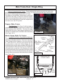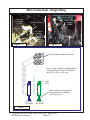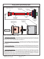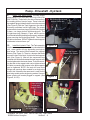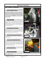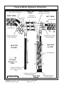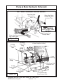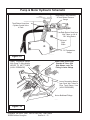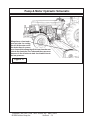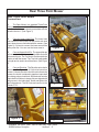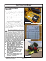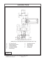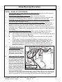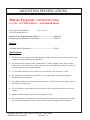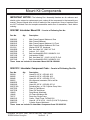
1
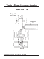
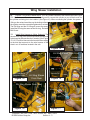
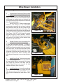
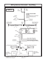
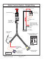
INTERSTATER
Assembly Instruction
Manual
Massey Ferguson
Model: 5435, 5445, 5455 & 5460
Cab - 2 Wheel Drive - Standard Hood
INTERSTATER
Tractors equipped with additional options, special equipment, tractor manufacturer modifications,
new tractor models, or Customer alterations may prevent this Mount Kit from being properly
mounted to the tractor. Alamo Group is not responsible for modifications to the MountKit to
accommodate these differences.
ALAMO INDUSTRIAL
1502 E. Walnut
Seguin, Texas 78155
210-379-1480
Manual P/N 02981905
Published 09-04
© 2004 Alamo Group Inc.
TO THE OWNER/OPERATOR/DEALER
All implements with moving parts are potentially hazardous. There is no substitute for a cautious, safe-minded
operator who recognizes the potential hazards and follows reasonable safety practices. The manufacturer has
designed this implement to be used with all its safety equipment properly attached to minimize the chance of
accidents.
BEFORE YOU START!! Read the safety messages on the implement and shown in your manual.
Observe the rules of safety and common sense!
WARRANTY INFORMATION:
Read and understand the complete Warranty Statement found in this Manual. Fill out the Warranty Registration Form
in full and return it to within 30 Days. Make certain the Serial Number of the Machine is recorded on the Warranty
Card and on the Warranty Form that you retain.
INTRODUCTION
ABOUT THIS MANUAL:
The intent of this publication to provide the competent technician with the information necessary
to perform the CORRECT Assembly to the Alamo Industrial Product. This will, in turn provide for
complete customer satisfaction
It is hoped that the information contained in this and other Manuals will provide enough detail to
eliminate the need for contact of the Alamo Industrial Technical Service Dept. However, it should be
understood that many instances may arrive where correspondence with the Manufacturer is necessary.
CONTACTING MANUFACTURER: (Please help us Help You! Before You Call! )
Alamo Industrial Service Staff Members are dedicated to helping you solve your problem, or
your customer’s service problem as quickly and efficiently as possible. Unfortunately, we receive
entirely to many calls with only a minimum amount of information. In some cases, the correspondent
has never gone out to look at the equipment and merely calls inquiring of the problems described to him
by the operator or customer.
Most calls received by Alamo Industrial Service can be classified into approx. 6 general categories.
1.
Hydraulic or Mechanical Trouble Shooting.
2.
Request for Technical Information or Specifications.
3.
Mounting or Fitting Problem.
4.
Special Service Problem.
5.
Equipment Application Problems.
6.
Tractor Problem Inquiries.
HOW YOU CAN HELP:
Make sure the call is necessary! Most of the calls received may not be necessary if the Dealer
Service Technician would do the following.
1.
Check the Service Information at your Dealership provided by Alamo Industrial, This
would include, Service Bulletins, Information Bulletins, Parts Manuals, Operators Manuals, Assembly
Manual or Service Manual, many of these are available via the Alamo Industrial Internet site (www.AlamoIndustrial.Com). Attempt to diagnose or repair problem before calling.
2.
If a call to Alamo Industrial is needed, Certain Information should be available and ready
for the Alamo Industrial Service Staff. Such information as, Machine Model, Serial Number, Your Dealer
Name, Your Account Number and Any other information that will be useful. This information is vital for
the development of a prompt and correct solution to the problem. This will also help to develop a
database of problems and related solutions, which will expedite a solution to future problems of a similar
nature.
3.
The technician may be asked to provide detailed information about the problem
including the results of any required trouble shooting techniques. If the information is not available, The
technician may be asked to get the information and call back. Most recommendations for repairs will
be based on the procedures listed in the Service Manual / Trouble Shooting Guide and Information
provided by customer.
CONTACT ALAMO INDUSTRIAL:
Alamo Industrial, 1502 E. Walnut St. Seguin TX. 78155, Technical Service Dept. PH: 830-379-1480
Interstater (MF-5435 , 5445 , 5455 & 5460 Asy. Man.) 09/04
© 2004 Alamo Group Inc.
Index - 1
INDEX - ASSEMBLY INSTRUCTION
Page
Index
Introduction..................................................................................... Index 1
General Index................................................................................. Index 2 & 3
User / Assmbly Notes..................................................................... Index 4
Section 1
Pre-Dilivery Check List...................................................................... 1-1 to 1-4
Section 2
Mainframe Assembly......................................................................... 2-1 to 2-6
Prepare Tractor................................................................................. 2-2
Prepare Main frame........................................................................... 2-2
Mount Frame Mounting Rails............................................................ 2-2
Removed Parts From Tractor.......................................................... 2-2
Install Mainframe............................................................................... 2-3 to 2-4
install Lift Cylinder and Lift Cylinder mount...................................... 2-4
Connect Cylinder hydraulics to Tractor hyd supply........................... 2-5
Section 3
Pump - Driveshaft - Hyd. Tank.......................................................... 3-1 to 3-7
Pump & Driveshaft Schematic.......................................................... 3-2
Prepare Tractor................................................................................. 3-2
Install Driveshaft & Pumps................................................................ 3-3 to 3-4
Connect Fittings & Hoses To Pumps............................................... 3-5 to 3-6
Connect Hoses to Frame.................................................................. 3-6
Connect Hoses to Tank ................................................................... 3-6
Install Return Pressure Gauge......................................................... 3-7
Install Oil Level Sight Glass in Tank.................................................. 3-7
Install Oil Temperature Gauge........................................................... 3-7
Install Motor & Valve Tank Return Lines............................................ 3-6 to 3-7
Section 4
Wing Mower Installation..................................................................... 4-1 to 4-13
Wing Mower Cut Off Switches.......................................................... 4-1 to 4-5
Wing Mower Hose Connections....................................................... 4-6 to 7-13
Wiring Schematic.............................................................................. 4-7 to 4-9
Pump & Motor Hydraulic Schematic................................................. 4-10 to 4-13
Interstater (MF-5435 , 5445 , 5455 & 5460 Asy. Man.) 09/04
© 2004 Alamo Group Inc.
Index - 2
INDEX - ASSEMBLY INSTRUCTION
Page
Section 5
Rear Mower Installation..................................................................... 5-1 to 5-8
Initial Start-Up Procedure................................................................... 5-4 to 5-7
Lubrication chart................................................................................ 5-5
Hydraulic Tank Filling Procedure....................................................... 5-6
Section 6
Tractor & Mower Mounting Requirements......................................... 6-1 to 6-5
Mount Kit Component Inventory list................................................... 6-4 to 6-5
Interstater (MF-5435 , 5445 , 5455 & 5460 Asy. Man.) 09/04
© 2004 Alamo Group Inc.
Index - 3
Section 1
INTERSTATER
Massey Ferguson
5435 , 5445, 5455 & 5460
Cab - 2 Wheel Drive
Standard Hood
PRE-DELIVERY INSPECTION
CHECKLIST
Interstater (MF-5435 , 5445 , 5455 & 5460 Asy. Man.) 09/04
© 2004 Alamo Group Inc.
Section 1 - 1
MACHETE PRE-DELIVERY INSPECTION CHECKLIST
Pre-Operation Inspection:
Check the following items before operating the unit to
assure that they are properly assembled. (See following page 1-4 for component location)
Saftey Equipment:
___
___
___
___
___
___
___
Operators Manual is with Unit.
The Safety Decals are installed as listed in the Assembly Manual.
Valve operation plate is installed.
Operators cage or Tractor Cab is in place
Deflectors are installed on the Mower Head
Tractor Rops or Cab with seatbels installed properly.
All Foot Guards and safety switch are installed and functional.
Frame:
___
___
___
___
___
___
Axle Plate Bolts are torqued.
Head Mounting Bolts tightened.
Frame attaching Bolts tightened.
Front Support Bolts are torqued.
Hydraulic Tank mounting Pins / Bolts in place correctly.
All Welds inspected toinsure proper welds and locations.
Hydraulic System:
___
___
___
___
___
___
___
Oil Level in Hydraulic Tank is within the sight gauge. (Item 5 page 1-4)
Hose connections are tight.
Hoses do not have any kinks or twist in them.
Front Pump Shaft adapter bolts are tight.
Front Pump Shaft Coupler / Drive Shaft is lubricated and has an anti-seize compound
on the Splines of Pump and Shafts.
The Pump Drive Shaft has correct alignment.
Suction Hose has no leaks or kinks.
Flail Mower Head:
___
___
___
___
___
___
___
___
___
Skid Shoe Bolts are torqued to 120 ft-lbs
Motor Bolts are torqued to 120 ft-lbs
Belt Alignment& tension adjustment is correct.
Cutter shaft bearings are properly lubricated
Roller bearings are properly lubricated
Blades swing freely.
All Pins and Clips for Rear Mower are installed
Clutch on Rear Mower has been checked for proper adjustment and conditions per
parts book reguirments.
All Belt guards are installed correctly.
Interstater (MF-5435 , 5445 , 5455 & 5460 Asy. Man.) 09/04
© 2004 Alamo Group Inc.
Section 1 - 2
MACHETE PRE-DELIVERY INSPECTION CHECKLIST
Tractor Mower Operation Inspection:
Using all Safety precautions, operate the Tractor and Mower unit for 30 minutes and
while the unit is running check the following items: Note! Only make adjustments after
the mower has been turned off and all motion has stopped and all hydraulic pressure
has been relieved.
___ Check for Hydraulic oil leaks at the hose connections
___ Operate the boom and mower head throughout its full range of motion and check
for hose's rubbing, pinching, or kinking.
___ Make sure the Return Filter Gauge is reading in the Green after Oil is warm.
___ Check the function of the Mower Head On-Off Valve and switch for proper function
___ Make sure that the tractor will not start with the mower on-off switch in the on
position.
___ Check the Blade Rotation for the Rotary Mower Head to make sure it is turning
Clockwise looking from the top of the mower deck.
___ Make sure the control valve boom movements agree with the valve operation decal.
___ Make Sure Boom Movement operates as expected and is smooth and under control
(no air in the control system)
___ Look for any unusual or excessive noise or vibrations.
___ Make sure the left rear wheel of the tractor stays on the ground when the boom is
fully extended horizontally with 200 lbs. placed on the outside of the mower head.
Post-Operation Inspection:
___ Check that the oil in the hydraulic tank has not turned milky in color or has foam on top.
___ Check that there are no loose fasteners or hardware.
Interstater (MF-5435 , 5445 , 5455 & 5460 Asy. Man.) 09/04
© 2004 Alamo Group Inc.
Section 1 - 3
Tractor - Mower Component Location
For Check List
Pumps, Hyd.
Tank & Cover
Right Wing
Flail
Rear Flail
Interstater (MF-5435 , 5445 , 5455 & 5460 Asy. Man.) 09/04
© 2004 Alamo Group Inc.
Section 1 - 4
Section 2
INTERSTATER
Massey Ferguson
5435 , 5445, 5455 & 5460
Cab - 2 Wheel Drive
Standard Hood
Main Frame Asy.
Interstater (MF-5435 , 5445 , 5455 & 5460 Asy. Man.) 09/04
Section 2 - 1
© 2004 Alamo Group Inc.
Main Frame Dual / Single Wing
Prepare Tractor:
Remove Components from Tractor. There are items that must be removed from tractor that
will not be used before the mainframe can be mounted. The steps on the right side has to be removed.
(See Figure 1). Before beginning any work on Tractor
the Negative Ground Battery cable needs to be disconnected from the battery to protect the electrical system.
Before reconnecting Battery cable check all connections
that you have made and make certain all components of
the tractor are in the OFF position.
Prepare Main Frame:
The Main frame (See Figure 2) will be bolted up
under the tractor at the rear of the tractor to a Rear Frame
Mount weldment (P/N 02981801). The front of the main
frame bolts to the front frame support weldments (P/N
02981813 LH Weldment & P/N 02981814 RH Weldment)
(See Figure 2 & 3). .
Mount Frame Rails To Tractor:
Figure 1
Mount to Front of Tractor
1.
Install the Front Frame Support Mount Weldments.
LH Side of
(P/N 02981813 LH Weldment & P/N 02981814 RH
Tractor
Weldment) (See Figure 3 & 3A). .There is a LH and a RH
Right Wing
Frame Support Mount Weldment to mount main frame
OnlyMainframe
to.. These will bolt to the front of the tractor with two
Shown
mounting bolts on each side. When Starting the two
mounting bolts it will work best to install the RH Side (See
RH Side of
Figure 2) and the LH Side (See Figure 3). Do not tighten the
Tractor
two mount bolts on each side , this will allow you to align
mounting bolts easier. Move to the rear of the tractor under
Mount to
the rear axle, check the threaded bolt holes in the rear axle
Rear of Tractor
housing. Remove any plugs or bolts that will be in the way.
Figure 2
(See Figure 4 & 5)
Front Frame
Support weldment
bolts to tractor
Looking from Front
of Tractor to Back
Removed Tractor
Parts that will not be
used
Mainframe to
frame rail mount
bolts
Mainframe
Figure 3
Frame Mounting Rails LH
Front Side
RH
Side
Support
Figure 3A
Interstater (MF-5435 , 5445 , 5455 & 5460 Asy. Man.) 09/04
Section 2 - 2
© 2004 Alamo Group Inc.
Main Frame
(Front
LH
Side
Support
Main Frame Dual / Single Wing
2.
Install Rear Support Weldment. The rear support weldment P/N 02981801 bolts to the tractor rear
axle housing (See Figure 5, 5A & 6), The rear axle housing has threaded holes in it. Shown below is with
the tractor rear wheels removed for illustration and to make it easier to install weldments. Use caution
when assembling this part, it is heavy approc 135 lbs.
Frame MountUse Jacks to lift it and clamp it to the jacks where it
ing Rails RH
wont fall. This is a two person step.
Side
3.
Tightening Mainframe Bolts. With all the bolts
Mainframe
installed, the bolts at the front of the mainframe to the
frame mounting rails, the bolts through the rear of the
mainframe support weldment. Tighten the bolts beginning with the bolts that mount the frame rail mount to the
tractor in the front (See Figure 3 & 4). Second tighten
the four bolts that mount the frame rail to the frame rail
mounts (See Figure 3) . Next tighten the rear mainHose Mounting Bracket
frame bolts that connects the rear of the mainframe to
the tractor rear axle housing. Once all the bolts are
Figure 4
tightened you can remove any floor jacks from under
main frame.
4.
Install RH Wing Lift frame. The wing lift frame
pivots on two hinge pins. When installing these pins
they must be aligned in a way that will allow the retaining
bolt to be installed. The Right side and the Left side will
install in the same way (See Figure 7 & 8). The wing lift
frame pivots on two hinge pins. When installing these
pins they must be aligned in a way that will allow the
retaining bolt to be installed. The Right side and the Left
side will install in the same way (See Figure 7 & 8)
Bolt to rear Axle Support Weldment
P/N 02981801 that is bolted to rear
tractor axle
5.
Install Lift Cylinder Mount Weldment . The lift
cylinder mount is a bolted on main frame weldment
(See Figure 8). Note the bracket also have the transport
lug welded to it.
Figure 5
Rear Axle Support
Weldment P/N 02981801
that is bolted to rear
tractor axle
Mainframe
under
tractor
Note: this Part is heavy
approx 135 lbs
Figure 5A
Figure 6
Interstater (MF-5435 , 5445 , 5455 & 5460 Asy. Man.) 09/04
Section 2 - 3
© 2004 Alamo Group Inc.
Main Frame Dual / Single Wing
6.
Install the Lift and Tilt Cylinders. Install the Lift cylinder and the Tilt Cylinder. When installing these
they must be installed with the rod end clevis grease fitting facing up and out (See Figure 10 & 11). The
Wing Lift Cylinders MUST have lift control spacer installed to control wing lift height (See Figure
10 & 11). Do not remove any shipping plugs from
cylinders or hoses until you are ready to install the hoses,
this will keep the system and components clean while unit
is being assembled.
7.
Tilt and Lift Cylinder Controls. The Cylinders are
powered by the tractor hydraulic system. The hoses for the
cylinder hoses will plug into the back of the tractor hydraulic
outlets. The Tractors factory hydraulic controls will be used
to control the wing lifting and fold. The hydraulic kit to instal
hoses are included in mount kit. (See Figure 12). When
running hoses from Cylinders to the rear of the tractor make
certain not to cross the hoses of cylinders at the remote. If
cylinders are not functioning properly check hose to make
Figure 6A
certain cyl. hoses are connected correctly (See Figure 13).
RH
Side
Shown
Frame Hinge
Pins
RH Side
Front
Shown
Hyd Hose
Bracket
Hinge
Pin
Figure 7
Figure 8
RH Wing Lift Cylinder Mounting Weldment
Transport
lug
Mainframe
Lift Control
Spacer must
be installed
on Lift Cylinders
Grease
Fittings
must face
up & out
Figure 9
Wing Lift
Frame
Figure 10
Interstater (MF-5435 , 5445 , 5455 & 5460 Asy. Man.) 09/04
Section 2 - 4
© 2004 Alamo Group Inc.
Wing Lift
frame
Main Frame Dual / Single Wing
Install with
Hyd. fittings
to rear
Tractor Remote
Hydraulic
Outlets
Wing Lift Cylinder
Wing Fold
Cyl.
Lift Control
Spacer
Grease
Fittings
must face
up.
Figure 11
Figure 12
Tractor Remote Hydraulic Outlets.
○
○ ○ ○ ○
○ ○ ○ ○ ○ ○ ○ ○ ○ ○ ○ ○ ○ ○
○ ○ ○ ○ ○ ○ ○ ○ ○ ○ ○ ○ ○ ○ ○ ○
○ ○ ○ ○ ○ ○ ○ ○ ○ ○ ○ ○ ○ ○ ○ ○ ○ ○ ○ ○ ○ ○ ○ ○ ○ ○
○
○
○
○ ○
○ ○
○
○
○ ○
○ ○
○
○ ○
○ ○
○
○
○ ○
○
○
○ ○
○ ○
○
○ ○
○ ○
RH Wing
Tilt Cylinder
○
Hoses for the Lift and Tilt cylinders are the
same size Qty 3 of Hose P/N 02905100
(#4 - 4FJX - 4FJX X 114" Long
○
○
○
○ ○ ○
○
Vent
Plug
Make certain lift control spacer
was installed on Lift cylinder,
See Figure 10 & 11
RH Wing
Lift Cylinder
Figure 13
Interstater (MF-5435 , 5445 , 5455 & 5460 Asy. Man.) 09/04
Section 2 - 5
© 2004 Alamo Group Inc.
NOTES
Interstater (MF-5435 , 5445 , 5455 & 5460 Asy. Man.) 09/04
Section 2 - 6
© 2004 Alamo Group Inc.
Section 3
INTERSTATER
Massey Ferguson
5435 , 5445, 5455 & 5460
Cab - 2 Wheel Drive
Standard Hood
Pump, Driveshaft &
Interstater (MF-5435 , 5445 , 5455 & 5460 Asy. Man.) 09/04
Section 3 - 1
© 2004 Alamo Group Inc.
Pump & Driveshaft Schematic
Spline Clamp Yoke
Shaft End of
Driveshaft
NF Thread
Bolts
Tube End of
Driveshaft
Single Pump for
Right Wing Only
Figure 1
Pulley Adapter
Spacer
NC Thread
Bolts
12
12
12
12
Pump Mount
Weldment
Tractor Engine
Pulley
123456
123456
123456
Install Driveshaft, Pump & Tank:
1. Gain Access to Tractor Engine. The hood side panels are removed to revel the tractor engine (See
Figure 2). Remove the engine guards on the left or right hand side of tractor (See Figure 3). This will allow
you access to the Tractor Crankshaft Pulley. (See Figure 1).
2. Remove the Cast piece on Front of Bolster. The casting on the front bolster of tractor will need to be
removed, it is a bolt on component. This casting will not be used so set it aside to save with the tractor
(See Figure 4).
3. Install Pulley Adapter Spacer. The Pulley adapter spacer (P/N 02979238) bolts to the crankshaft pulley
with four 7/16" - NF X 1-3/4" long bolts & Lockwashers (P/N 02976344 Bolts & 00022200 Lockwasher.The
four holes in adapter for these bolts are the non threaded ones as the crankshaft pulley holes are threaded
4. Install Driveshaft (Shaft End). Insert driveshaft half (Shaft half with 4 bolt flange yoke against
crankshaft pulley adapter). This 4 bolt flange yoke bolts to engine crankshaft pulley adapter (P/N
02979238) with four 7/16" - NC X 1-1/4" bolt (P/N 02976344 bolt & 00022200 lockwasher). The Complete
driveshaft asy (P/N 02973712A) is a two piece shaft and tube design. When installing it note that when
the shaft and tube are slid together they must be timed at the universal joints.
Interstater (MF-5435 , 5445 , 5455 & 5460 Asy. Man.) 09/04
Section 3 - 2
© 2004 Alamo Group Inc.
Pump - Driveshaft - Hyd tank
5.
Install pump Mount Weldment. ( P/N 108423)
Bolt the pump mount weldment to the front of the
tractor where the factory front casting was removed.
The pump mount weldment will bolt to the same
holes as the casting did. The driveshaft will be
sticking through the front of the tractor. (See Figure
1 & 5)
6.
Install Driveshaft (Tube End) The Tube end
of the driveshaft will have a splined clamp yoke on it.
When installing the tube end of driveline the universal joints of each end MUST be aligned / Timed (See
Figure 1 & 5). Driveshaft P/N 02973712A
7.
Install Hydraulic Pump (Pumps to operate
Mower Motor). Install the Pump (single pump for
only one wing. P/N 702717) Align the splines of the
pump shaft with the splines of the driveshaft yoke.
Push the pump on till the pump is seated into the
Splined yoke. MAKE CERTAIN that the splined
yoke is not on the pump shaft so far that it will rub the
pump housing, there must be a gap. If the gap is OK
tighten the flange yoke bolts until the clamp yoke is
secures to pump shaft. Slide the pump into the
pump mount weldment until the flange of pump is
seated into center hole on mount. (See Figure 1 & 5)
Sides of Hood
Remove
Figure 2
Right Side Shown
8.
Install Pump Retaining Bolts. Install the two
bolts that retain the pump to the pump mount
weldment and tighten them. (See Figure 1 & 5)
Figure 3
Sides Screen Shields
Remove
Pump Mount Weldment
Front Bolster Casting
Bolts On
Figure 4
Figure 5
Interstater (MF-5435 , 5445 , 5455 & 5460 Asy. Man.) 09/04
Section 3 - 3
© 2004 Alamo Group Inc.
Pump - Driveshaft - Hyd tank
9.
Install Tank Mount Plates. The tank mount
plates have a LH (P/N 02977222 LH) & RH (P/N
02977238 RH). These bolt to the side of the tractor in
the existing bolts of tractor frame. These holes will
have plastic plugs in them that will have to be removed
(See Figure 6). Bolt the Tank Supports to the side of
the tractor, note there is a LH & a RH side . The mount
plates will also have hose rings (P/N 02978281) bolted
to them, use longer bolts to bolt hose rings on. The
LH side hose ring (Shown in Figure will be used on
the RH side bolted to the Mainframe support weldment
when mounting the Single Wing Model. The LH and
RH bolt on the same, DO NOT tighten the tank support
weldments to tractor frame yet.
10.
Install the Hydraulic Tank. The Tank assembly
is in the common parts crate which is ordered with the
unit , crate number will vary depending on single or
dual wings. The tank will bolt between the support
frames (See Figure 8). There is a bumper that bolts
across the front of the tank, it bolts to the tank support
rails (See Figure 9). After all the components are
installed with all the bolts started the tank support rails
can be tightened to the tractor frame. The bolts mounting the tank to the support rails can be tightened and
the bolts connecting the bumper to the tank supports
can be tightened. NOTE: the tank will have more
fittings and openings than needed for a single wing
model, this is because the same tank is used for the
dual wing models as the single wing modes. Some of
these opening will remain plugged or capped. (See
Figure 8, 9 & 10).
4 Bolt holes to mount tank
support frame rails
Figure 6
LH Tank Support
Frame Rail Shown
Figure 7
4 Bolt holes to
mount tank
support frame
Figure 8
Tank Mounting Bolts,
LH Side Shown
Figure 9
Interstater (MF-5435 , 5445 , 5455 & 5460 Asy. Man.) 09/04
Section 3 - 4
© 2004 Alamo Group Inc.
Front Bumper
Pump - Driveshaft - Hyd tank
11.
Prepare Pump Fittings DO NOT remove any caps or plugs on hydraulic hoses or connections until
you are connecting them, this will keep dirt out. The Pump will need to be prepared for connecting the
hoses. There are fittings that must be changed.
Pump
The Fittings in the pump should already be installed
when you receive it from the factory (See Figure 10).
The Pressure Out Port to Wing from pump fitting will
Pressure
need to be change to a 90 degree elbow fitting (See
Fitting
Figure 10 ). One of the Two large caps on the tank
suction ports will need to be replaced with an elbow
Suction
fittings and hose barbs It is best to use the most outward
Hose &
opening (See Figure 10). Coat the fittings that screw
Fitting
into pumps and tank with a pipe sealer (NOT Teflon
Tape), do not put excess sealer on OD of fittings and
Pump
none on ID of fittings (See Figure 9). Install the elbow .
Case
The Suction hose will need to be cut to length (See
Drain
Figure 11), Install the hose onto the pump, using clean
Hose
and proper oil pour oil into the sution hose so it will run Figure 10
into the pump, this will ensure the pump does not start
up dry. IMake certain that you have installed the hose
clamps on the suction hose, install the other end of the
suction hose onto the hose barb of the tank elbowTighten
the Hose clamps on the suction hose on both ends (See
Figure 11).
12.
Install the Pump Case Drain Hose. The pump
case drain hose connects to the tank, there are two
fittings on the tank that the case drain can connect to
because the same tank is used on the single wing
model as the dual wing model. The case drain hose can
connect to eather one and the other will remain plugged.
showh here we connected to thew front one (See Figure
Cut Suction Hose
10, 11 & 12). make certain tos use a pipe sealant on
pipe fitting (Do not use Teflon tape) Tighten the hose Figure 11
fitting now.
Tank Return
Filter Asy
Tank Hose
Return Fitting
Pump
Case
Drain
Hose
Figure 12
Pump Pressure
Hose to Cutter
Figure 13
Interstater (MF-5435 , 5445 , 5455 & 5460 Asy. Man.) 09/04
Section 3 - 5
© 2004 Alamo Group Inc.
Tank Fill &
Vent Cap
Cannister Manual Container
Pump - Driveshaft - Hyd tank
13.
The Tank Return Filter & Hose Fitting. The
return filter is located on top of the tank (See Figure
13). There is a Tee fitting that screws into the back
side of the filter housing (See Figure 14). This is for
the Oil return hose from the cutter housing. The
fitting should be a Tee as shown with a plug in one
end of the Tee. This is because the same tank is
used on the dual wing and the single win. If this Tee
is used leave one end plugged (See Figure 14). The
Return hose has a straight end at the filter return, the
elbow is a separate fitting that screws into the Tee.
The other end of this hose will have 90° fitting on the
hose (See Figure 15, 16, 19 & 20). Note the blue
plastic tie on the return hose in figure 14.
14.
Connect Motor Pressure Supply Hoses to
Pump. The Pump has pressure hose. The fitting on
the Left Side (Left side of Tractor) is the pressure
supply for the RH Wing Motor. The hose for the RH
Wing should be marked with a red plastic tie on it.
Connect the pressure hose at the pump now, this
will be the strait fitting on the end of the hose and
connect to the bulkhead fitting on the frame bracket,
this end of the pressure hose has a 90° fitting. This
hose will run up and across tank to the right side of
tractor. This hose will run along side the return hose
to the tank (See Figure 15, 16, 19, 20 & 21). Do not
connect the pressure hose to the frame hose bracket
until it has been run through the sleeving with the
return hose, see step 15.
15.
Connect Tank Return Hose. Connect the
return hose to the tank return bulk head fitting on
frame (See Figure 15). Run the return and pressure
hose through a piece of sleeving (furnished in kit)
then run the two hoses through the hose rings.
MAKE CERTAIN you mark which hose is connected to the pump for pressure and which is connected to the return filter assembly for return, this is
important. Connect the two hoses to the frame hose
bracket bulk head fittings (See Figure 15). The
pressure hose from pump will always connect to the
top fitting and the return hose will connect to the
bottom fitting on this bracket (See Figure 15, 19, 20,
& 21).
Return
Pressure
Gauge
Oil Return
Fitting
Oil
Level
Sight
Glass
Oil
Temperature
Gauge
Figure 14
Frame hose
bracket with bulk
head fittings
Hose Ring
Hose
Sleeving
Pressure
Hose 90°
Pressure
Hose 90°
Return
Hose 45°
Return
Hose 90°
Figure 15
Retun Hose
connects to
deck collinf
tubes
Interstater (MF-5435 , 5445 , 5455 & 5460 Asy. Man.) 09/04
Section 3 - 6
© 2004 Alamo Group Inc.
Pressure Hose
Connects to Motor
Figure 16
Pump - Driveshaft - Hyd tank
16.
Hose Connections at head. The hose connections to the mower motor and cooling tubes is
shown here as a reference to show that these hose
MUST NOT be mixed up and connected wrong.
This is why it is so important to mark the hoses so
you always know which is pressure and which is
return. If these hoses are connected wrong (pressure hose to cooling tubes) the cooling tubes and/or
other components will be damaged. The cooling
tubes will be expanded out of shape from the excess
pressure forced through them (See Figure 19). The
hose fittings at the motor pressure and the return
hose has a straight end at fitting. The Pressure hose
has a 90° fitting at the bulkhead fitting and the return
hose has a 45° fitting (See Figure 15, 16, 19, 20 & 21)
17.
Install Return Filter Pressure Gauge. The
return filter pressure gauge screws into the side of
the return filter housing. This gauge is a low pressure gauge that is marked in green and red areas.
(See Figure 17). The Oil Pressure return gauge has
a rubbery tip on top of it, the tip till have to have the tip
of it cutoff. Using a utility knife (or suitable knife) cut
the tip off now (See Figure 17). This will need to be
done before unit is run.
Oil Return
Pressure
Gauge
Figure 17
Oil Return
Pressure
Gauge
Oil Level
Sight
Gauge
18.
Install the Oil Level Sight Glass. The Oil Level
sight Glass screws into the Hydraulic tank and may
already be installed into the tank when it is received
from the factory. This is to be covered with oil when
tank is at operating level. (See Figure 18)
Figure 18
Oil
Temperature
Gauge
19.
Oil Temperature Gauge. The oil temperature
gauge is a mechanical gauge that measures the
temperature of the oil in the tank. This gauge may be
installed into tank when received from factory or it
may need to be installed. Install as shown (See
Figure 18).
Case Drain Hose
Pressure Hose to
Motor
20.
Head Hose Connections. The hose connections for the head are shown here as a reference
only. The wing hinge mounts and motor cut off
switches must be installed before the hoses can
be connected to the head. See the section 4 for
mounting the head and the cut off switches.
Figure 19
Interstater (MF-5435 , 5445 , 5455 & 5460 Asy. Man.) 09/04
Section 3 - 7
© 2004 Alamo Group Inc.
Return Hose to
Cooling Tube
Pump - Driveshaft - Hyd tank
Pressure Hose From Pump has
a 90° Fitting Connects here.
Pressure Hose Motor has
a 90° Fitting Connects here.
NOTE: The Pressure hose will
always be connected to the top
fitting and the return will always
connect to the bottom.
123
123
123
123
123
123
123
123
123
123
1234
1234
1234
1234
1234
Return Hose to Tank Return Filter
has a 90° Fitting Connects here.
cccccccccccccccccccccc
Return Hose from Cutter Head
Cooling Tanks has a 45° Fitting
Connects here.
1234
1234
1234
1234
1234
Main Frame w/ hose bulkhead fitting
RH side of tractor looking from front to rear of tractor
Single Wing Shown, Dual Wing has metal cross over pipe with a Tee in it for the return.
Figure 20
Note 45° elbow on
bulkhead fitting tha
hose connects to
Figure 21
Interstater (MF-5435 , 5445 , 5455 & 5460 Asy. Man.) 09/04
Section 3 - 8
© 2004 Alamo Group Inc.
Section 4
IINTERSTATER
Massey Ferguson
5435 , 5445, 5455 & 5460
Cab - 2 Wheel Drive
Standard Hood
Wing Mower
Installation
Interstater (MF-5435 , 5445 , 5455 & 5460 Asy. Man.) 09/04
Section 4 - 1
© 2004 Alamo Group Inc.
Wing Mower Installation
Wing Cut Off Switch:
1.
Assemble Brackets & Magnetic Switches.
Shown below will reference to a dual wing model.
a single wing will connect the same with half as
many parts. Locate the Magnetic switch mounting bracket, dual wings there will be two of these
(See Figure 1). If Dual wings the two brackets will
have the switches mounted on the opposite side
(See Figure 2). Once these have the switches
bolted on lay the brackets aside for now. (See
Figure 20)
2.
Assemble Magnetic Switch Activators. This
magnetic switch activator has a magnet inside
and a cover that must be installed (See Figure 4).
There are brackets that these bolt to. With dual
wings there is a LH and RH bracket. Bolt the
Magnetic activators to the brackets (See Figure 5)
LH Bracket Shown). Note there are two sets of
mounting holes. In figure 5 the set that have the
bolts through them is used to shut wing off at 45
degree up. If the other set of holes are used wing
mower will shut off at 90 degrees up. The 45
degree setting is recommended for standard applications.
3.
Install Switch Brackets & Head Mounting
Brackets. Use a hoist to lift the Wing Mower and
position it for mounting. DO NOT get under Mower
while lifted on a hoist (See Figure 6). Mower is only
be positions so that switch brackets and hinge
brackets can be installed to head, this must be
done before mower can be mounted to lift frame.
LH Wing Magnetic
Switch & Bracket
Small Screw Hole
Slotted Hole for
switch wires
Small Screw Hole
Figure 1
Magnetic
Switch
Switch
Mounting
Screw
Figure 2
Magnetic
Stich
Activator
Case
Cover
Figure 3
RH Wing Magnetic
Switch & Bracket
Bracket
Mounting
Holes
Figure 4
Interstater (MF-5435 , 5445 , 5455 & 5460 Asy. Man.) 09/04
Section 4 - 2
© 2004 Alamo Group Inc.
Magnetic Switch
Wire Plug
Magnet
Inside
Wing Mower Installation
Wing Cut Off Switch: (continued)
4.
Install Mower Rear Mounting Brackets &
Magnetic Switches. The Mower Hinge Link has a
LH & RH (See Figure 7). These brackets will slide
over the Hinge Pin which is bolted to the mower
deck at the factory. There are two Threaded holes
in the end of the hinge pin (See Figure 7) These
two holes serve dual purpose. First they hole the
hinge bracket on and the Magnetic Activator Bracket
on. Some times you will need to loosen the Hinge
pin to align the two holes so the bracket will bolt on.
(See Figure 8 & 9). Tighten the two mounting bolts
in to the hinge pin. The Hinge bracket will still turn
free.
Mount Magnet Activator to
these hole for 45 degree
shut off.
RH
Bracket
Shown.
Figure 5
Mount Magnet Activator to
these hole for 90 degree
shut off.
LH Wing
Rear Hinge
Bracket
Two
Threaded
Holes in
Hinge Pin
Figure 6
Always use overhead
hoist to position mower
deck
LH Wing Shown
From Rear
Hinge Pin
Bracket
LH Wing Shown
RH Wing Shown
From Rear
Magnetic Activator
Switch Bracket
Magnetic Activator
Switch Bracket
Figure 8
Figure 7
Hinge Pin
Bracket
Figure 9
Interstater (MF-5435 , 5445 , 5455 & 5460 Asy. Man.) 09/04
Section 4 - 3
© 2004 Alamo Group Inc.
Wing Mower Installation
5.
Install Mower Front Mounting Brackets. The Mower Hinge Front Bracket has a has a LH & RH
(See Figure 10). These brackets will slide over the Hinge Pin which is bolted to the mower deck at the
factory. This bracket will be bolted to the Lift frame
with four bolts. This hinge Pin WILL NOT have
threaded holes as the rear hinge pin did.
LH Wing Shown
From Front
6.
Install Wing Mower to Lift Frame. Using the
over head hoist position the Mower Deck (See
Figure 10) to where the front hinge bracket will align
with the lift frame. Install at least two of the mounting
bolts and snug them down.
7.
Install the wire harness to wings. The Wire
harness will have a lead to each wing. These can be
determined by the length, the longer lead will go to
the left wing. There is apiece of square tube welded
to the lift frame on the back for the wire harness to be
run through (See Figure 11). The wire harness will
be run down and under the round bar of lift frame.
Leave harness here for now.
Figure 10
LH Wing Front Hinge
Pin Bracket
LH Wing Shown
From Front
8.
Install Magnetic Switch Pickup & Bracket as
well as the rear hinge bracket. The Rear hinge
Bracket will install similar to the way the front does,
but not the same because the Magnetic switches
and brackets bolt on with it. Before installing the rear
Hinge bracket locate the magnetic Switch Bracket
(See Figure 12). There are two spacers about 3/4"
long that must be installed between the magnetic
switch bracket and the hinge Bracket (See Figure
12), Also the wire harness must be run between
these two spacers and between these two brackets
(See Figure 13 & 14). Install the remaining two bolts
and tighten all the hinge bracket bolts, this will
include the front hinge bracket bolts. (See Figure 21)
Figure 11
9.
Plug Magnetic Switch into Wire Harness.
The wire harness will have two wires coming out of
the loom near where they go over the magnetic
switches with butt connectors on them ( a black wire
and a black wire with white stripe). These wires are
to be connected to the magnetic switch black wire
and the black wire with white strip of the magnetic
switch (See Figure 14) . Plug these together now
and continued to run wire harness up behind the
hinge and on up to the mower decks motor. (See
Figure 21)
LH Wing Shown
From Front
Figure 12
Interstater (MF-5435 , 5445 , 5455 & 5460 Asy. Man.) 09/04
Section 4 - 4
© 2004 Alamo Group Inc.
Wing Mower Installation
10.
Connect Tilt Cylinder to Mower Deck. The Tilt Cylinder connects to the mower head (See Figure
15 & 16). Note you will need to remove the belt guard to connect this cylinder so you will have room for
the cylinder mounting pin to be installed (See Figure 16). When connecting the cylinder, the grease
fitting on the rod end must face up, the locking collar on
the cylinder must face up and be tightened on rod end.
The RH Wing and the LH Wing will mount the same.
Install the RH wing the same as the LH wing . Reinstall
Belt Guard.
11.
Install Wire Harness to Motor Solenoid. The
thumb nut on top of the solenoid will allow the solenoid
to be turned to different direction if needed. (See Figure
17 & 21) The Wire Harness to the head will have a plug
at the end that connects to the wire harness to the
electric cut off switches located in the cab.
Figure 13
Wire Harness to
Motor
Wire Harness to
Magnetic Swithc
Figure 14
LH Wing Shown
From Rear
LH Wing Shown From Front
Clevis Locking
Collar
Cylinder Rod
Clevis with grease
fitting up
Cylinder Pin
LH Wing Shown
From Rear
Figure 15
RH Wing Shown From Rear
Soleniod
Wire Harness
Figure 16
Figure 17
Interstater (MF-5435 , 5445 , 5455 & 5460 Asy. Man.) 09/04
Section 4 - 5
© 2004 Alamo Group Inc.
Wing Mower Installation
Connecting Mower Motor Hoses:
1.
Connect Motor Pressure & Return Hoses
to Mower Deck. Connecting the Motor Hoses is
very critical that they a re connected to the correct
fittings, If these hose are connected backwards it
will damage the cooling tubes on the deck, the
cooling tubes cannot take the pressure it will make
them swell up and bulge.
IMPORTANT FACT. When connecting the
hoses to the fittings on the mainframe
crossmember remember the top hose is always
thew pressure hose and will only connect to the
motor, never the cooling tubes on the deck. The
bottom hoses are the return hoses and will always
connect to the cooling tubes on the mower deck.
(See Figure 18 & 19). The RH wing will connect
the same as the LH mower (Shown). IMPORTANT. On the RH Wing the top hose is pressure
and connect to the Motor and the bottom hose
connects to the Tank return.
Pressure Hose
f/ Pump
top
hose
bottom
hose
Figure 18
Return hose
Figure 19
3.
Install Pump Cover. The front pump cover
will bolt to the tank, this cover will cover pumps and
all hoses and/or fittings connected to the pump
(See Figure 20). Set the cover down over the
pumps. Align the hove in cover with the tabs
welded to the tank (See Figure 20).
4.
Install Rear Mower. Go on to the Install rear
mower section which will also include the Initial
Start up procedures. DO NOT START Tractor
until you have completed the initial start up section.
Return Hose from
Colling tube on deck
Pressure
Hose
2.
Double Check all Hose Connections. Before operating the mower make certain all hydraulic hoses are connected correctly. IT IS MOST
critical that you make certain NO HIGH PRESSURE hoses are connected to the wet tubes of
the mower deck, The wet tubes will expand (swell
up) and be damage if the High Pressure hose is
connected to the deck wet (cooling) tubes. See
Figure 21, 22, 23, 24, 25, 26 & 27. Looking at all
these figure before going on to next step is important.
Pressure Hose
w/ 90 degree
bend to Motor
Figure 20
Interstater (MF-5435 , 5445 , 5455 & 5460 Asy. Man.) 09/04
Section 4 - 6
© 2004 Alamo Group Inc.
Wiring Harness Schematic - Dual Wing
Figure 21
Right
Switch
Left
Switch
DOUBLE WING MOWER
SHOWN
(Single Wings have only the Right
Wing Motor Solenoid Valve
harness)
Brown
Brown
Red
Black
3 Terminal
Connector
Cavity
Plug
Left Wing Motor
Solenoid Valve
White
Black/Wht
Right Wing Motor
Solenoid Valve
Yellow
Black/Wht
Yellow
Fuse
Red
Left
Switch
Red
Right
Switch
Brown
White
Yellow
Brown (Start Terminal)
Brown (Starter Solenoid)
3 Terminal
Connector
Red (to Accessory Terminal)
Black (Ground @ Tractor Starter)
White
Yellow
Left Wing Safety Cut-off Switch
White
Right Wing Safety Cut-off Switch
White
Black
Black
B/W
Left Wing
Motor Solenoid
Valve
Black/White
#1
#2
#1
Black
#2
Interstater (MF-5435 , 5445 , 5455 & 5460 Asy. Man.) 09/04
Section 4 - 7
© 2004 Alamo Group Inc.
Right Wing
Motor Solenoid
Valve
Motor Control Switch - Single Wing
# 16 Yellow
# 16 Red
ON / Off
Switch Plug
Push-Pull Switch
# 12 Brn
Fuse Holder
with Fuse
(10 Amp Fuse)
Starter Solenoid Wire
Starter Solenoid Wire
Switched Power Supply
Ground
#16 Black
Solenoid
Connector
Ring Connector
to Ground
Connecters Shipped Loose in
Separate Plastic Bag
#16 Black
(-)
#16 Black
#16 Red (+) to
Switched Power
Supply
# 16 Yellow
Figure 22
# 12 Brown Line
Connector to
Starter Solenoid
Interstater (MF-5435 , 5445 , 5455 & 5460 Asy. Man.) 09/04
Section 4 - 8
© 2004 Alamo Group Inc.
Solenoid Connector
at Cutter Valve
Wiring Harness
Wire Harness Connections:
1. Disconnect Battery Cable. Disconnect the
battery cables before attempting any of the
electrical connections, this is to protect the
tractor electrical system as well as the mower
electrical connections. Electrical connections
should never be attempted with the battery
connected. Use Ohm Meters to test electrical
connections.
2.
Motor Control Switch. The wiring harness schematic list the plug, wire type, wire color, and where the
wires connect. The wire harness will be shipped
complete. The wire harness will need to be connected correctly or it will not function properly. DO
NOT operate any unit that is not functioning correctly
(See Figure 22 & 23).
Figure 23
Cutter Solenoid & Wire
Harness Connection
Tractor Starter and
Starter Connections
3.
Connect Starter Solenoid Wires. The starter
solenoid wire are the two brown wires. The tractor
solenoid activation wire (See Tractor Model Wire
Schematic) will need to be cut and rerouted through
these two brown wires. Connect the two wires at the
starter solenoid (See Figure 22 & 23)
4.
Connect Wiring to Cutter Valve Solenoid. The
plug for the cutter valve solenoid will plug onto the
solenoid without any modifications to plug or solenoid
(See Figure 24)
Figure 24
5. Connect Cutter switch electrical supply. The red
wire to power switch supply will be connected to a
power supply that is only active when the ignition key
is in the on position. Also make certain that it is
connected to source that will not interfere with the
switch or that the switch will interfere with other
components of the tractor.
6.
Connect the Ground Wire. The ground wire will
need to be connected to the tractor where it will have
a good uninterrupted connection.
7.
Install Motor Control Switch. The motor control
switch will be mounted in the cab in a convenient
place for the operator. The location of this switch is up
to the installer to decide.
Figure 25
Interstater (MF-5435 , 5445 , 5455 & 5460 Asy. Man.) 09/04
Section 4 - 9
© 2004 Alamo Group Inc.
Pump & Motor Hydraulic Schematic
TRACTOR
REAR
Return to Tank from
Wet Tubes of RH Wing
RIGHT WING
T
OU
Return
Line
Tee
Return to Tank from
Wet Tubes of LH Wing
Mainframe
Tube Cross Over
LEFT WING
Hose Sleeving
OUT
Hose Sleeving
IN
IN
Pressure from Pump
to RH Wing Motor
OUT
Pressure from Pump
to LH Wing Motor
TRACTOR
LH SIDE
TRACTOR
RH SIDE
IN
Indicates
Direction of
Flow
IN
Hose Sleeving
Return to Tank from
Wet Tubes of RH & LH
Wing
Pressure from Pump
to RH Wing Motor
Figure 26
TRACTOR
FRONT
Interstater (MF-5435 , 5445 , 5455 & 5460 Asy. Man.) 09/04
Section 4 - 10
© 2004 Alamo Group Inc.
Pressure from Pump
to LH Wing Motor
Pump & Motor Hydraulic Schematic
LEFT WING HYDRAULIC MOTOR SHOWN
Case Drain from
Motor to Motor
Valve
Return from Motor
to Rear Wet Tube
and on to Tank
NEVER CONNECT
HIGH PRESSURE
HOSE TO WET TUBES
ON DECK !
High Pressure from
Pump to Motor
Return from Front
Wet Tube to Tank
Figure 27
LH Wing
Pump Case
Drain
RH Wing
Pump Case
Drain
Tandem Pump, Inner Pump for RH Wing
& Outer Pump for LH Wing
RH Wing
Pump High
Pressure
Line
Hose
Sleeving
Tandem
Pump
LH Wing Pump High
Pressure Line
LH Wing
Pump Suction
Line
Figure 28
RH Wing
Pump Suction
Line
Cyl System Supply
Pump Suction Hose
Interstater (MF-5435 , 5445 , 5455 & 5460 Asy. Man.) 09/04
Section 4 - 11
© 2004 Alamo Group Inc.
Pump & Motor Hydraulic Schematic
Tank Return Filter Assembly
& Tank Return Pressure
Gauge
Tank Return Hose from
Cylinder Control Valve
to Tank
Tank Return Hose from
Wet Tubes on LH &
RH Wing Decks
Oil Level
Sight
Glass
Oil Temperature
Gauge
Figure 29
Upper Connection Always
from Pump To Wing Motors
NEVER TO WET TUBES
(HIGH PRESSURE)
Main Frame Cross Over
Bracket & Tubes (RH
Side Shown, note Tee
Fitting in lower fittings
Lower Connection Always
from Deck Wet Tubes to
Filter Tank Return Line
(LOW PRESSURE)
Nut on Bulkhead Fittings
Figure 30
Interstater (MF-5435 , 5445 , 5455 & 5460 Asy. Man.) 09/04
Section 4 - 12
© 2004 Alamo Group Inc.
Pump & Motor Hydraulic Schematic
Wings have a front and a
rear wet tube for cooling
the oil. At the outer end of
the decks there is a cross
over hose which allows the oil to cross from the rear
tube to the front tube,The Tubes and the cross over
hose are in the oil return to tank circuit which has to
be low pressure..
Figure 31
Interstater (MF-5435 , 5445 , 5455 & 5460 Asy. Man.) 09/04
Section 4 - 13
© 2004 Alamo Group Inc.
NOTES
Interstater (MF-5435 , 5445 , 5455 & 5460 Asy. Man.) 09/04
Section 4 - 14
© 2004 Alamo Group Inc.
Section 5
INTERSTATER
Massey Ferguson
5435 , 5445, 5455 & 5460
Cab - 2 Wheel Drive
Standard Hood
Rear Mower Installation
Interstater (MF-5435 , 5445 , 5455 & 5460 Asy. Man.) 09/04
Section 5 - 1
© 2004 Alamo Group Inc.
Rear Three Point Mower
Rear Three Point Mower
Connection:
1.
The Rear Mower is a standard Three Point
Hitch mounted mower that is PTO driven through a
driveline. It will be sent already assembled with the
driveline tied to it. (See Figure 1)
2.
Connect Lower Hitch Pins. The lower hitch
pins connect to the lift arms of the tractor with click
pins, these pins are furnished with the mower. (See
Figure 2). It is best to connect the lower arms of the
three point first. You can use the lower arms to
Figure 1
3.
Connect Upper Hitch Pin. The upper hitch pin
will connect to the top three point adjustable Link with
a pin and click pin. The Top Link is furnished with the
tractor not with the mower. The Top Link is adjustable
in length and is used to level the mower. (See Figure
3)
4.
Connect Driveline . The Driveline arrive tied to
the mower (See Figure 1 & 4). Cut the ties loose from
mower. Connect the clutch end of the driveline to the
mower, the clutch is retained to tgearbos input shaft
by a clamp yoke on clutch hub. Slip the clutch onto the
input shaft untill holes in clamp yoke are aligned with
the grooves in the inbut shaft. Install and tighten the
two bolts and nuts. The QD Yoke end connect to the
Tractor PTO.
Figure 3
Figure 2
Figure 4
Interstater (MF-5435 , 5445 , 5455 & 5460 Asy. Man.) 09/04
Section 5 - 2
© 2004 Alamo Group Inc.
Rear Three Point Mower
Rear Three Point Mower
Connection:
5.
Leveling the Rear Mower & Adjust gutting
Cutting Height. The Rear Mower is leveled with the
top Three Point Link. The Cutting Height is adjusted
by moving the Roller up or down by change the
bearing bracket mounting hole. The is a decal on the
deck next the Operators/ parts manual cannister
(See Figure 5 & 6)
6. Rear Mower Completly Connected. With the
rear mower completly connected. Check all Oil levels and grease mower components (See Figure 9)
before running mower. Also DO NOT start tractor if
the rest of the assembly to the interstater is not
done. Make certain that all hoses, compontents,
wiringing is completed and Oil Tank for interstater
has been filled with oil.
Figure 5
7.
Slip clutch is incorporated in the PTO driveline. It is designed to slip, absorb the shock load,
and protect the driveline. It is important that the
clutch lining plates slip when an obstacle or load
heavier than clutch setting is encountered. Therefore, if the machine sits outside longer than 30 days
and is exposed to rain and/or humid air it is important to make sure that the clutch lining plates are not
rusted/corroded together. Before using the mower
use the following procedure to make sure the clutch
will slip and give the overload protection required.
(See Figure 8) This is a required step because the
driveline has been sitting and may be stuck.
A. Loosen nuts on springs until the springs can
freely rotate, yet remain secure on bolts.
B. Attach mower to tractor and start the tractor.
Set the engine speed at 1200 RPM.
C. Mark outer plates with marker, paint or any
form that will work for you to tell if the compo
nents of the clutch slipped.
D. Engage the PTO (approximately one second) and then quickly disengage it. The
friction lining plates should break loose
(check the mark).
E. Turn tractor off and tighten the nuts on the
springs to their original position of 1-5/16"
compressed spring length.
Figure 6
Figure 7
Interstater (MF-5435 , 5445 , 5455 & 5460 Asy. Man.) 09/04
Section 5 - 3
© 2004 Alamo Group Inc.
Rear Three Point Mower
Rear Three Point Mower
Connection:
8.
Slip clutch is incorporated
in the PTO driveline. It is designed to slip, absorb the shock
load, and protect the driveline. After the first hour of operation, the
slip clutch should be checked for
overheating. After this first
check, the slip clutch should be
checked weekly or anytime there
is overheating. To adjust the slip
clutch, tighten the spring bolts 1/8
(maximum) turn at a time. Bolts
should NEVER be adjusted to the
point where the springs are compressed solid. Minimum spring
length is 1-1/8". The slip clutch
should be checked periodically
and adjusted to compensate for
wear. The lining plates are 1/8"
thick when new. Replace after 1/
32" wear. If the mower has been
idle for an extended period of time,
or in wet weather, before operating check to be sure the friction
lining plates are not frozen or
rusted together. Should this
freezing occur refer to the procedure described in the "Seasonal
Clutch Maintenance" section on
the next page. There are four friction lining plates in the slip clutch.
These should be checked weekly
for oil or grease, wear, and moisture which could cause corrosion
on the drive plates. (See Figure 7)
1-5/16" Standard
1-3/16" Min.
FRICTION
LINING
PLATE
SPRING BOLT
WITH NUT
Figure 8
NOTE: Above information is
listed as a reference only
and will not apply to mower
assembly.
Interstater (MF-5435 , 5445 , 5455 & 5460 Asy. Man.) 09/04
Section 5 - 4
© 2004 Alamo Group Inc.
Lubrication Points
LUBRICATE ALL POINTS BEFORE OPERATING MOWER FIRST TIME
A
B
C
D
E
F
Lift Frame Pivot Pin
Wing Mower Belt Idler Arm
Cuttershaft Bearings
TIlt Cylinder Rod Ends
Lift Cylinder Rod Ends
Roller Bearings
G
H
J
K
L
Rear Mower Idler Arm
Banjo Bearings
Banjo Coupling
Driveline Yoke
Driveline slip
Figure 9
Interstater (MF-5435 , 5445 , 5455 & 5460 Asy. Man.) 09/04
Section 5 - 5
© 2004 Alamo Group Inc.
Initial Start-Up Procedure
INITIAL START-UP PROCEDURE:
1.
2.
3.
4.
5.
6.
Check all nuts and hex head capscrews to ensure all are tight and all lock washers are fully
compressed (flattened).
Check all hoses and hydraulic connections. Make certain they are secure.
Inspect all moving parts and besure that no wires or hoses will be caught or pinched when
the tractor or the INTERSTATER is in operation. Tie down loose wires and hoses.
Thoroughly grease the INTERSTATER and install a lubricap on each grease fitting. Refer to
the Operation and Maintenance Section.
Jack front of tractor up enough to allow axle to pivot through its full range. While turning
wheels through their limits, right and left, swing them up and down. Look for interference
between tires and any part of the INTERSTATER. If interference occurs, shims (not
furnished) must be welded to axle pivot stop or steering arm to limit the movement enough to
avoid interference. Tractors with an adjustable front axle may require an outward adjustment
of the wheels.
To fill the INTERSTATER reservoir with new, clean hydraulic oil, follow the steps below.
Refer to the Operation and Maintenance Section for specifications. (See Figure 10)
A.
With a hydraulic jack raise the right side of the tractor. This will tilt the tank and allow
only a minimum amount of air when filling.
B.
Avoid hydraulic contamination by filtering the hydraulic oil while filling the hydraulic
tank.
C.
Filter buggies or carts are commercially available for hydraulic system clean-up.
These consist of a high-efficiency, high-capacity filter, a circulating pump, a drive
motor, and hoses for connecting the overhauled machine’s hydraulic system.
D.
After the first 10 hours of operation, replace the hydraulic filter with a new one. An
extra Filter Element is provided for you. Refer to the Operation and Maintenance
Section for instruction.
7.
After the Interstater mower is
completely assembled to the
tractor and with the wings on
the ground, fill the mower hy
draulic tank above the oil level
sight gauge approximately 5" or
1" below the top of the tank.
8.
With mower ON/OFF switches
in “ON” position and tractor fuel
cut off, crank engine for about
30 to 45 seconds to allow oil to
fill pumps and motors. Check
the oil level in the sight gauge.
If no oil is seen add oil to bring
the level up to the sight gauge.
NOTE: Do not fill the tank with
oil above the level of the sight
Figure 10
gauge. Over filling the tank with
oil after the initial filling may re
sult in oil being discharged
through the air filter on top of the hydraulic tank. Start the tractor and run it for 2 minutes and
then turn it off. Again check the oil level in the sight gauge. If the oil level is in the sight gauge,
the unit is ready to run. If no oil is seen, add oil to bring the level up to the sight gauge.
Interstater (MF-5435 , 5445 , 5455 & 5460 Asy. Man.) 09/04
Section 5 - 6
© 2004 Alamo Group Inc.
Initial Start-Up Procedure
CAUTION
ROTATING KNIVES!
Remove all foreign objects and stand clear of
cutter units. DO NOT GET NEAR!
NOTE: On tractor hydraulic powered circuit only, make certain that there is full flow from tractor
hydraulic system to control valve. Refer to tractor manual.
9.
After hydraulic system is fully charged and functioning properly, switch cutter units on, then
speed engine up to 540 RPM PTO speed. Maintain this speed for about 5 minutes. Check
complete INTERSTATER, look for any leaks,loose connections, or anything that could cause
premature wear or failure.
FINAL CHECK
Run INTERSTATER for about 1/2 hour at full speed. Check for leaks and vibrations. Frequently
check oil temperature. Make certain it does not exceed 180 deg.
NOTE: When raising wings, make certain there is no interference with mower, frame, cylinders or
tractor. Lift wings slowly.
CAUTION:
DO NOT leave unit unattended, and COMPLY WITH ALL WARNING DECALS.
If unit starts to make unusual noise, stop unit and check oil level. Also check for frothy oil which
would indicate a leak on suction side of system.
Interstater (MF-5435 , 5445 , 5455 & 5460 Asy. Man.) 09/04
Section 5 - 7
© 2004 Alamo Group Inc.
NOTES
Interstater (MF-5435 , 5445 , 5455 & 5460 Asy. Man.) 09/04
Section 5 - 8
© 2004 Alamo Group Inc.
Section 6
INTERSTATER
Massey Ferguson
5435 , 5445, 5455 & 5460
Cab - 2 Wheel Drive
Standard Hood
Mounting Specifications
& Mount Kit Numbers
Interstater (MF-5435 , 5445 , 5455 & 5460 Asy. Man.) 09/04
Section 6 - 1
© 2004 Alamo Group Inc.
MOUNTING SPECIFICATIONS
Massey Ferguson
5435/5445/5455/5460
w/ Cab - w/2 Wheel Drive - w/Standard Hood
7.50-16 (I-1) Max Front Tire
As of: 9-11-04
16.9-28 (R-4) Max Rear Tire
Mainframe Assy: Right Hand Only (Offset 5") ……..…..…..........02981881
Component Crate: RH Only w/Tractor Hyd ………..…….......... 02981312
Options:
Lift Chain Kit (See Spec Below) ……………………………..... 701836
Specifications:
1. The tractor must be equipped with a through-hood exhaust. If it has an A-post exhaust instead, then
it must be rerouted horizontally beneath the cab.
2. The tractor must be equipped with a “standard hood”. Tractors equipped with a “high-visibility”
hood require a special mainframe to allow clearance for servicing the battery which is located just
below the right side of the operator platform .
3.
If a rear head is needed, it can be ordered as a 96" centered or 88" with an 8.5" offset.
4. The mainframe should allow approximately 9" of ground clearance when equipped with the
maximum tire sizes listed above.
5. The right hand steps must be removed for head clearance. Ingress/egress on the right is otherwise
blocked by the control stand.
6. Two lift chains are recommended for centered heads, while offset heads should only be ordered
with one.
7. Mount kit includes Neapco style driveline with double U-joints.
8. The right hand only component crate for tractor hydraulics includes hoses and fittings for coupling
to the rear tractor hydraulic remotes. Note, the tractor must be equipped with two remotes.
Interstater (MF-5435 , 5445 , 5455 & 5460 Asy. Man.) 09/04
Section 6 - 2
© 2004 Alamo Group Inc.
MOUNTING SPECIFICATIONS
Interstater (MF-5435 , 5445 , 5455 & 5460 Asy. Man.) 09/04
Section 6 - 3
© 2004 Alamo Group Inc.
Mount Kit Components
IMPORTANT NOTICE: The following Part / Assembly Numbers are for reference and
should not be ordered as replacement parts, unless all the components in that assembly are
wanted. These will break down to bills of material of the components. Some of numbers listed
are NOT individual Parts but complete assemblies and/or box of assemblies. Check before
ordering.
02981881 Interstater Mount Kit :
Part No.
Qty
Consist of Following Part No.
Description
02981801
1
Main Frame Support Weldment, Rear
02981809
1
Main Frame Weldment
02981813
1
Main Frame Support Weldment, LH Front
02981814
1
Main Frame Support Weldment, RH Front
5312316
4
Washer 25/32” ID, Hardened
02918600
4
Bolt, Hex Head 3/4” -10NC X 2” Gr 8
00037200
8
Locknut, 3/4” -10 NC
02975669
8
Bolt, Hex Head M20-P2.5 X 60 MM PL 10.9
02971158
12
Lockwasher, 20 MM
02981885
4
Bolt, Hex Head 3/4” - 10 NC X 4-3/4” PL Gr 8
02971342
4
Bolt, Hex Head M20-P2.5 X 45 MM PL 10.9
These items are included in Interstater Mount Kit P/N 02981881
02981312 Interstater Component Crate : Consist of Following Part No.
Part No.
Qty
Description
002364
1
Hose #16-16FJX -16FJX45- 65.5
002365
1
Hose #16-16FJX -16FJX90- 62.5
002482
1
Hose #16-16FJX -16FJX90- 72” LG
002501
1
Wire Harness,Interstater ,RH1st w/Cab
02966874
1
Cable Boot
02968160
1
Hose #16-16FJX -16FJX90- 52” LG
02973712A
1
Driveshaft Asy. w/ 7/8-13 Spline Clamp Yoke
02977222
1
Plate, LH Tank Mount
02977238
1
Plate, RH Tank Mount
108423
1
Pump Mount, Machined
108436
1
Lift Frame Weldment RH
702717
1
Pump Asy, Single Pump
02981313
1
Carton , Small Parts - MF5400 C/2
02905100
3
Hose #4 - 4FJX- 4FJX -114LG (f/ Lift & Tilt Cylinders)
02980151
1
Cylinder Support Weldment
These items are included in Interstater Component Crate P/N 02981312
Interstater (MF-5435 , 5445 , 5455 & 5460 Asy. Man.) 09/04
Section 6 - 4
© 2004 Alamo Group Inc.
Mount Kit Components
02981313 Carton of Small Parts: Consist of the following Item No.
Item No.
Qty
Description
00763977
1
Decal, Notice To Owner
02906300
2
Sleeving f/ Large Hoses - 48” LG
02919400
2
Adapter Hyd Elbow 16MJ -16MJ 45°
02958920
1
Adapter Hyd Elbow 20MP -20MJIC 90°
02961115
1
Adapter, Pipe, 20FP-20FP, 90°
02961286
1
Adapter, Hyd Straight
02962748
1
Decal, ON-OFF Switch Cutter Valve
02964028
1
Switch, PUSH - PULL
02966873
1
Drawing, Boot Installation
02979238
1
Plate, Spacer Machined
803213A
1
Operators Manual Asy, Interstater
02981314
1
Bolt Bag, MF5400 Cab / 2 Wheel Drive
02980177
1
Switch Mount Weldment
02978281
2
Hose Ring Weldment
00751878
1
Pipe Plug, 1-1/4” w/ Socket Hex Head
002338
1
Cap, 3/4” Female Pipe
02822100
3
Adapter, Hyd Elbow
02811300
3
Check Valve LT-50-4BR
651312
3
Coupler Half, Male
03200285
1
Decal, Watch Your Step
000859
8
Plastic Tie
72414000
1
Adapter Pipe, 1-1/4” Close Nipple
108748
1
Spacer, Cylinder Collar
Carton of Small Parts is included in Component Crate P/N 02981312
02981314 Bolt Bag: Consist of the following Item No.
Item No.
Qty
Description
00003901
4
Lockwasher, 3/4” PL
00022200
8
Lockwasher, 7/16” PL
00037200
4
Locknut, 3/4” NC
02918600
4
Bolt, Hex Head 3/4” -10NC X 2” PL Gr8
02963645
4
Bolt, Hex Head 3/4” -10NC X 1-3/4” PL Gr8
02971158
12
Lockwasher, 20 MM
02971342
10
Bolt, Hex Head M20-P2.5 X 45 MM PL 10.9
02975781
4
Bolt, Hex Head 7/16” - NF X 1-3/4” PL Gr8
02976344
4
Bolt, Hex Head 7/16” - NC X 1-1/4” PL Gr8
02975669
2
Bolt, Hex Head M20-P2.5 X 60 MM PL 10.9
00002000
2
Bolt, Hex Head 3/8” - NC X 3/4” PL Gr5
00015800
2
Locknut, 3/8” - NC
00011100
2
Flatwasher, 3/8” Std.
Bolt Bag is included in Carton of Small Parts P/N 02981313
Interstater (MF-5435 , 5445 , 5455 & 5460 Asy. Man.) 09/04
Section 6 - 5
© 2004 Alamo Group Inc.
NOTES
Interstater (MF-5435 , 5445 , 5455 & 5460 Asy. Man.) 09/04
Section 6 - 6
© 2004 Alamo Group Inc.
© 2004 Alamo Group Inc
Insterstater Assembly Manual
Massey ferguson
5435, 5445, 5455 & 5460
2004 Edition
P/N 02981905
iInterstater (MF -5435 , 5445, 5455 & 5460 Asy. Manual) 09/04
© 2004 Alamo Group Inc.