1
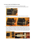
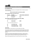
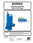
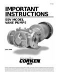
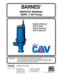
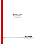
K 60, 63
K 60/63.58.0306. Eng/Digital
K60-63
SERVICE INSTRUCTION
1 (10)
SERVICE INSTRUCTION
K 60, 63
K 60/63.58.0306. Eng/Digital
This service manual covers the pumps K 60 and K 63 in following designs:
Illustrations, e.g. (3/2) indicates the Fig. number using the first digit and the second digit
indicates the position on that illustration.
Type F Wet Pit Installation
Installed on a guide rail system with a quick-release base elbow, the base elbow is bolted to
the floor of the sump. The volute is equipped with an adapter to be connected to the
discharge elbow. Two twin guide rails are mounted to the discharge elbow to steer the pump
into right position when hoisted up and down.
Type P, Wet Pit Portable or fixed installation
A version of pump which is suitable for temporary or permanent installations. The pump is
equipped with a fabricated steel stand and either a threaded (G, NPT) or plain hose
connection.
When installed the minimum water level in the wet well for continuous operation should
not be below half the height of the stator. For intermittent operation the pump should not
be used when water level is below the top edge of the pump house.
The pumps are divided into three categories: Standard, EX and FM. The difference
between the three is the wear plate. In the standard version there is a hole drilled for the
moisture switch (optional). On the EX there is no hole and the FM version has a threaded
hole.
Safety precautions
Note: When carrying out any repairs the safety instructions in the Service instruction as in the
Installation and Operating Instructions, especially the section ”Safety” must be observed.
When carrying out any work correctly sized and adequately dimensioned hoists and other tools
should be used. Do not work under a suspended load.
Before doing any maintenance or repairs to the pump, make sure that it is isolated from
the power supply, and also that no one can reconnect it whilst it is being worked on.
When raising the pump, do so by means of a rope or a chain through the handle. Never
move or lift a pump by means of its cable.
If the pump has been working in sewage or similar effluent, use a power or steam hose to
clean the pump before working on it, and observe personal hygiene precautions.
Electrical work on the pumps should only be carried out by suitably qualified personnel.
General maintenance advice
Before assembly all parts should be carefully checked.
Parts being reused must be in perfect condition and should be carefully cleaned before
fitting.
Warning !
The pump and its electrical cables must be disconnected from any
power source by a qualified electrician before any inspection or
service is performed!
Removal from the wet well
Hoist the pump from the sump and rinse clean.
2 (10)
SERVICE INSTRUCTION
K 60, 63
K 60/63.58.0306. Eng/Digital
Oil filling and oil change
The oil chambers of the PUMPEX submersible pumps have been filled at the works with
oil.
Oil: 0.48 l nontoxic oil e. g. BP Enerpar M002.
A regular oil change is not necessary, provided that the leakage sensor signal is not
activated. PUMPEX submersible seal monitoring system (optional) indicates by means of
an inspection light that water has entered into the oil and that the mechanical seal is
leaking and must be replaced.
ATTENTION When using the submersible pump in process or raw
water applications an oil which is not injurious to the environment
should be used.
ATTENTION Waste oil should be disposed of in a proper manner.
Oil change on site
Note: When carrying out an oil change the regulations covering usage of oil must be observed.
Waste oil must be disposed of in a proper manner.
Tilt pump so that it lies horizontal. Position oil plug hole at the underside of the pump. Oil
is released by unscrewing the oil plug screw (1/1) with sealing washer (1/2) in the volute.
The oil will then flow out and into container. It may be slow because oil chamber has not
been vented.
TIP: To speed up emptying, insert a small bore tube (Ø 3-4mm)
deep into oil chamber to aid unrestricted venting.
Refilling oil
Place motor in position opposite to fig.1, so that oil plug hole faces
upwards. Fill in oil slowly, allowing air to vent out through same hole.
Check and replace sealing washer if necessary.
Note: Don´t forget to tighten the plugs after completed filling.
2
1
Fig. 1
Disassembling the impeller
Lay pump on its side on the workbench (with the aid of a hoist),
taking care that it cannot roll over. Remove 3 screws (2/3) and
washers (2/4) holding bottomplate (2/5) to volute. Remove impeller
holding screw (2/1), with single washer (2/2). Remove impeller (2/6
by using an impeller pullers or if this is not available, the impeller can
also be removed using a large screwdriver. Wedge screwdriver
behind impeller through the discharge outlet, and tap outer tip of
blade with plastic hammer and rock impeller from shaft.Reassembly
takes place in reverse action.
6
5
4
2
3
1
Fig. 2
3 (10)
SERVICE INSTRUCTION
K 60, 63
K 60/63.58.0306. Eng/Digital
Disassembling the primary mechanical seal
Empty the oilchamber of oil and disassembling the impeller as above.
Remove impeller key (3/1) with pliers from the shaft.
Remove circlip (3/2).
Slide mechanical seal (3/3) with aid of rotating movement, carefully
from the shaft. Remove fixed ring (3/4) from oil chamber, taking care
to keep all parts thoroughly clean.
Note: Mechanical seal must always be exchanged as a complete unit.
4
Disassembling the volute
3
The Volute is a vortex impeller design and has got no wear rings.
Dismantle impeller and remove primary mechanical seal as described
above. Mark position of volute relative to motorhousing. Remove
volute by unscrewing 3 screws (4/1). Remove O-ring (4/2) from volute
and replace.
Disassembling the secondary mechanical seal (optional)
Remove volute as described above. Lay motor assembly on the
workbench on its side, so that it cannot roll over. Remove circlip (5/1)
with circlip pliers. Slide mechanical seal (5/2) with aid of rotating
movement, carefully from the shaft. Remove fixed ring (5/3) from
bearing lid. Taking care to keep all parts thoroughly clean.
2
1
Fig. 3
1
2
Note: Mechanical seal must always be exchanged as a complete unit.
Disassembling the lip seal
Fig. 4
Remove volute as described above. Lay motor assembly on the
workbench on its side, so that it cannot roll over. Collapse the lip seal
(5/4) in two places and prise it out with a screwdriver, taking care not
to damage the shaft and bore.
Disassembling the motor cable and cable cap
connection
Mark position of motorhousing relative to volute. Remove the three
screws holding the motorhousing to the volute.
Lift motorhousing, with a hoist, a few inches while holding impeller
down with a heavy screwdriver, jammed behind impeller through
volute outlet, to avoid damage to mechanical seals, and release
leakage sensor plug connection from leakage sensor probe (7/6). Lift
motorhousing clear of motor and hydraulics, and place on its side on
workbench. Snip all leads leading to stator (6/1), at the plastic butt
connection (6/2). Unscrew earth connection from the underside of the
motorhousing (6/3). Unscrew 4 screws (6/4) holding cable cap (6/5)
to motorhousing (6/6). Pull cable and cable cap from motor.
Disassembling the motorhousing
If motorhousing or stator needs to be replaced, then it is not
necessary to dismantle the hydraulics.
Proceed as when disassembling the motor cable and cable cap
connection up to placing the motorhousing on workbench. Do not cut
any stator leads. Disconnected leakage sensor lead (7/5, 7/6) and
unscrew earth lead (6/3).
3
2
1
4
Fig. 5
4
5
6
3
1
2
Fig. 6
4 (10)
SERVICE INSTRUCTION
K 60, 63
K 60/63.58.0306. Eng/Digital
Disassembling the upper bearing
When changing upper bearing, it is necessary for the shaft to be
supported to avoid damage to the lower bearing being inflicted as a
result of levering or tapping. Normally this will require dismantling of
pump hydraulics. Then the motorhousing is removed as described
above. This leaves rotorblock and rotor with top bearing (7/8)
accessible. Bearing can be removed using bearing pullers or levered
off with screwdrivers, O-ring (7/9) in motorhousing should be
replaced.
9
8
7
6
5
Disassembling the lower bearing & Shaft
This involves a total disassembly of the pump. Firstly remove
impeller, primary mechanical seal, secondary mechanical seal (or lip
seal), motorhousing and make sure oil is drained off. All described
above. Lay rotor assembly on its side. Remove bearing circlip (7/2)
and remove shaft circlip (7/1). Gently tap rotorshaft downwards
through the bearing lid. When shaft is removed the lower bearing can
then be pressed out. This is done by tapping the bearing out from the
rotor side of the bearing lid with a soft punch.
4
10
3
2
1
Fig. 7
Leakage sensor probe (optional)
When replacing the lower bearing, the leakage sensor probe can also
be replaced if necessary
Non EX versions: Remove plug from leakage sensor probe (7/6) if not
already removed. Release circlip (7/7) and remove probe (7/5).
EUROPEAN EX versions: Leakage sensor probe is held on with a small
L bracket. It is located on the motor side of the bearing lid.
AMERICAN FM versions: Leakage sensor probe is screwed directly into
bearing lid.
Disassembling the stator
The stator is held in by a compression fit only, so therefore it can only
be removed by pulling it out by force. Remove cable, cable cap and
motorhousing as described above.
The stator is then pulled out by means of a hollow cylinder. It is not
recommended to heat the housing as a means of removing stator
alone, but flash heating can assist in stator removal. The extraction
tool consists of a frame, a stop, a hydraulic cylinder and stator
pullers. The stator pullers is designed so that it can be inserted at an
angle to the bottom of the stator. There are 4 different sizes to suit
each stator bore.
The stator pullers is then pulled up along with the stator.
Fig. 8
5 (10)
SERVICE INSTRUCTION
K 60, 63
K 60/63.58.0306.Eng/Digital
Assembling
After reassembly perform pressure test.
Mounting the impeller
Lay pump on its side on the workbench (with the aid of a hoist),
taking care that it cannot roll over.
Push the impeller (9/6)onto the shaft. Lock the impeller from rotating
and fasten the impeller washer (9/2) and screw (9/1).
Fasten the 3 screws (9/3) and washers (9/4) holding bottomplate (9/
5) to volute.
6
Mounting the primary mechanical seal
It is important to keep the mechanical seal rubber parts dry to prevent
slip between rubber and metal components. If wear grooves are not
visible, then the mechanical seal can be refitted. If damaged the
mechanical seal must be replaced. When refitting a new mechanical
seal absolute cleanliness must be observed.Remove grease from the
shaft.
Clean seal seating area of the shaft and volute. Lubricate the boot of
the fixed ring (10/1) and place over the end of the shaft, taking care
that it is on straight and press into position in volute using insertion
tool. Place mechanical seal sleeve on to the shaft to protect the boot
of the rotating ring (10/2). Lubricate the boot of the rotating ring (10/2)
with soapy water, (do not allow soapy water to come in contact with
seal faces) and press carefully fully home with insertion tool as far as
the fixed ring. Care must be taken when sliding the mechanical seal
over key way slot.
Slide fixing washer (10/3) on and compress the mechanical seal
and insert circlip (10/4) into the groove in the shaft. Rotate the
shaft by hand a number of times so that the mechanical seal can
bed itself in.
Before filling in oil or carrying out any further assembly, check the oil
chamber for leaks. Finally screw back impeller and bottom plate (see
mounting the impeller).
5
4
2
3
1
Fig. 9
1
2
3
4
Fig. 10
Mounting the secondary mechanical seal motor side
(optional)
It is important to keep the mechanical seal rubber parts dry to prevent
slip between rubber and metal components. If wear grooves are not
visible, then the mechanical seal can be refitted. If damaged the
mechanical seal must be replaced. When refitting a new mechanical
seal absolute cleanliness must be observed.Remove grease from the
shaft.
Place support washer (11/1) on to shaft and slide it down into
the bearing lid.
1
2
3
4
Fig. 11
6 (10)
SERVICE INSTRUCTION
K 60, 63
K 60/63.58.0306.Eng/Digital
Clean seal seating area of the shaft and bearing lid. Lubricate the boot of the fixed ring
(11/2) and place over the end of the shaft, taking care that it is on straight and press into
position in bearing lid using insertion tool. Place mechanical seal sleeve on to the shaft to
protect the boot of the rotating ring (11/3). Lubricate the boot of the rotating ring (11/3)
with soapy water, (do not allow soapy water to come in contact with seal faces) and press
carefully home with insertion tool as far as the fixed ring. Care must be taken when sliding
the mechanical seal over key way slot.
Compress the mechanical seal and insert circlip (11/4) into the groove in the shaft.
Rotate the shaft by hand a number of times so that the mechanical seal can bed
itself in.
Before filling in oil or carrying out any further assembly, check the oil chamber for leaks.
Finally screw back impeller and bottomplate (see mounting the impeller).
Mounting the lip seal
Firstly remove grease from shaft. Replace support washer and place lip seal over shaft
and tap down home using insertion tool. Refit volute, making sure it lines up with
motorhousing according to marks put on earlier. Refit primary mechanical seal as above.
Before filling in oil or further assembly, check the motor/oil chamber for leaks.
Motor cable and cable cap connection
Replace cable and reconnect as per wiring diagrams in the
instruction book. New butt connections must be used to reconnect
leads to stator. Reconnect earth lead and reassemble in reverse to
above instructions, not forgetting leakage sensor probe and that it is
not trapped.
9
8
Mounting the motorhousing
When refitting be careful that leakage sensor lead is reinserted
carefully and is not kinked or likely to be caught under the
motorhousing.
7
6
5
Mounting the upper bearing
Lubricate bearing with grease and Refit bearing making sure O-ring
(12/9) is fitted back correctly into the groove in the motorhousing .
4
Mounting the lower bearing & Shaft
10
Place support washer (12/10) back in to bearing lid and press new
bearing back into bearing lid using insertion tool. Lubricate bearing
with grease and refit circlip. Support inside race of bearing with
fixture to allow shaft through. Press shaft down through bearing lid
and bearing.
3
Mounting the stator
Refitting of stator can only be done by means of a heavy press and
insertion tool.
7 (10)
2
1
Fig. 12
SERVICE INSTRUCTION
K 60, 63
K 60/63.58.0306. Eng/Digital
Tests
Air gap
When reassembling stator and rotor, the gap is set by the tolerances of the machined
parts and is not changeable.
High voltage test
A high voltage test is recommended if the pump has been repaired or reassembled.
Link all power leads together and apply a high voltage between earth and power leads. A
voltage of 1,800 volts (= 2 x rated voltage + 1000 volts) is used. This test should only last
one second. This test will show any breakdown of insulation.
Earth check
An earth check is recommended if the pump has been repaired or reassembled. This
involves checking the continuity between earth lead and the motorhousing (where earth
lead is connected). This can be done with a resistance meter.
Pressure test
This is performed to check sealing of the unit and is recommended if the pump has been
repaired or reassembled. All pressure testing must be carried out without oil in the
oil chamber of the volute.
Firstly drain the oil from oil chamber.
NOTE: It is absolutely essential the testing be carried out in the following manner to prevent
dislodging the lip seal in bearing lid.
Motorhousing/Volute connection
Remove pressure test screw (13/1) and washer (13/2) from oil
chamber of the volute. Screw pressure test probe, with sealing ring,
into test hole and apply pressure of 1/2 bar (7 psi) - not to be exceeded.
This process will check the sealing of the outer and inner mechanical
seal, leakage sensor probe and sealing between volute and motorhousing.
2 1
Motor connection
Remove pressure test screw (14/1) from motorhousing with seal
washer (14/2). Screw pressure test probe with sealing ring into test
hole and apply pressure of ½ bar (7 psi) - not to be exceeded. This
process will check the sealing of the motor chamber, i.e. cable entry
and sealing into the oil chamber.
Pressure test
Lower into water. Leave motor submerged for a few minutes, to allow
trapped air to excape, and observe any leaks, which is indicated by a
flow of bubbles.
Raise pump from water and disconnect pressure from motorhousing
first and then the oil chamber.
Fig. 13
2
1
Additional test
Fig. 14
The sealing between oil chamber and motorhousing (Mechanical/lip
seal & leakage sensor probe) can be checked by applying pressure to oil chamber as
above, and connect an U-tube to the motorhousing through the test hole, to detect
pressure difference in motorhousing. The U-tube should contain a small quantity of water
in the bend, if it displaces then there is a leak from the oil chamber. This is a dry test.
Run test
A dry run test should be done to check the amps, rotation, and power drawn against rated
data. See Starting and operating instruction for table of rated data. If this dry test is run
without oil in the oil chamber it should only be run for 12 seconds maximum otherwise
damage could occur to the mechanical seal.
8 (10)
SERVICE INSTRUCTION
K 60, 63
K 60/63.58.0306.Eng/Digital
Y 50/60 Hz
Ä 50/60 Hz
K 60 W 50 Hz
K 63 W 50 Hz
9 (10)
SERVICE INSTRUCTION
K 60, 63
K 60/63.58.0306. Eng/Digital
K 60 W, K 63 W 60 Hz
PUMP
K 60W/K 63W
Run capacitor:
K 60W 1.0 kW 230 V 60 Hz : 1x30 mfd
K 63W 1.4 kW 230 V 60 Hz : 1x20 mfd
K 63W 1.8 kW 230 V 60 Hz : 1x20 mfd
10 (10)