1
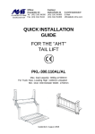
Office:
Factory:
Hauptplatz 23
ALUHEBETECHNIK Tel. (43) 2142 64260
Gesellschaft mbH Fax. (43) 2142 6434
Bahnstraße 34
(43) 2142 64360
(43) 2142 64366
A-2474 Gattendorf
E-Mail:
[email protected]
INSTALLER’S MANUAL
FOR THE “AHT”
TAIL LIFT
HTK-500ST/AL
HTK-750ST/AL
HTK-500ST/M
HTK-750ST/M
with underrun beam
Gattendorf, May 2007
SERVICE QUALIFICATIONS TO INSTALL
THE TAILGATE LOADER
The installer should be well trained in the proper procedure for installing the AHT before
beginning the installation.
Carefully read the manual before starting to install the AHT tailgate loader.
Only mature adults, age 18 and above, should install the AHT tailgate loader.
Installer should be well qualified for installing hydraulic equipment.
Installer should be well qualified for installing the electrical equipment.
INSTALLATION GUIDELINES
1) Remove bumpers, lights, tool box etc. from rear of vehicle if necessary.
2) Cut and shape the body and chassis to fit the tailgate.
3) Fixing the mounting device on the truck body.
4) Remove the pin from platform bearing
5) Position the mainframe under the truck. Then displace the power pack.
6) Fix the mounting brackets onto the truck main frame.
7) Mount the power pack again.
8) Energize the power pack.
9) Remove the mounting devices and lower the hoisting unit for approximately 40cm.
10) Position the platform and install the joint plate, the spring, the tube and the pin at the
platform bearing.
11) Lift up the lever arm and the closing cylinder and install the pins for lever arm - joint plate
12) Remove the tilting Lock.
13) Adjust the platform level.
14) Installing the platform lock.
2
UNPACKING THE TAILGATE LOADER
A complete unit will be shipped on one pallet consisting of two main units:
(1) Platform
(2) Main frame with lifting arms, cylinders,
power pack,mounting brackets, 2
button-remote-control and
installation manual.
Mounting Bracket
Pallet
Main Frame
Power Pack
Lifting Arms
Platform
CAUTION: Never lift the Main Frame with the hoisting
unit at the stabilizer.
(Lift cylinder will be damaged)
FORBIDDEN!!!
Always lift the complete unit evenly, as shown in the
picture, being careful to raise the lift arms at the same
time. Be sure the lift arms and the lever arms are
secured.
3
PREPARING FOR INSTALLATION
Remove rear lights, bumper, tool box and spare wheel, if
necessary.
Disconnect the battery cable to prevent damage to the
battery while welding.
Subframe Tie-down
Remove any obstruction attached to the frame of the
vehicle that would interfere with the installation. The
mounting brackets will cover the mainframe and subframe.
Installing on a truck body with roll-up doors or
without rear doors.
Cut out the rear of the frame, if necessary, as shown in the
installation drawings.
Reinforce the cut outs.
Truck bodies with rear doors.
Refrigerated bodies with swing doors need an end profile,
made from stainless steel, welded to the body as shown in the
drawing, on the right.
4
Mounting bracket
INSTALLATION INSTRUCTIONS
Installing the Mounting Device
- Fixing the mounting device
Center the mounting device on
the truck body floor.
Both mounting devices must
make a contact with the truck
floor end. Clamp both mounting
devices on the truck body floor.
- Platform Preparation
Before you can install the main frame you have to remove the 2 pins, the spring and the
tube from the platform.
1) Remove the pin from platform bearing on both sides.
2) Remove the spring on the right side.
Remove the tube on the left side.
5
INSTALLATION INSTRUCTIONS
Position the tailgate unit
- Position the main frame
- Install the mounting brackets on the main frame, but do not fix it.
- Place the main frame under the vehicle with lift arms attached using a floor jack, and
raise main frame to its approximate final position.
- Be sure to lubricate all pin surfaces before installing the pins.
- Raise the hoisting unit to the mounting device, remembering that the lift cylinders will
come apart if raised too high. (If necessary, raise the main frame closer to the vehicle chassis.)
- Install pins (Lift arm - platform) between
mounting device and hoisting unit.
- The main frame must be parallel with the
body.
-
IMPORTANT: SEE “TAILGATE KINEMATICS” THE
MAXIMUM AND MINIMUM MEASUREMENTS MUST BE
KEPT.
- Displace the power pack
- Before you can fix the mounting brackets, you have to
displace the power pack.
Loosen the 4 screws
M10x25 on the power
pack
Now displace the power pack
It is not necessarry to remove any hydraulic hoses, fittings
and electric wirings.
6
INSTALLATION INSTRUCTIONS
Position the tailgate unit
- Install mounting brackets
- Place the mounting brackets to its exact final position.
- Clamp the mounting brackets on the truck frame.
Mounting Bracket
Truck Main Frame
Screw Clamp
Check the
right-angled
- Fix the mounting brackets on the main frame.
- Drill 16mm (5/8”) holes into the chassis and mounting bracket.
Screw M16 (5/8”) is 8.8 Strength (Grade 8)
Max. Torque 195Nm (145ft lbs.)
Drill two holes in each bracket, put a bolt in each one and secure. Then drill the other holes.
Truck Main Frame
4 HOLES
ø 16mm (5/8“)
Screw Clamp
Mounting Bracket
NUMBER OF SCREWS PER MOUNTING BRACKET: 4 pieces
M16x50
- MOUNT THE POWER PACK AGAIN. FASTEN THE 4 SCREWS
M10x25
7
INSTALLATION INSTRUCTIONS
Energize the power pack
CAUTION: REMOVE TRANSPORT FILLER CAP AND INSERT DIPSTICK:
(There is no air hole in filler cap and the pump or reservoir will be destroyed)
Be sure the vehicle and the liftgate are of the same current (12V or 24V).
Fuse is in the power pack. (12V = 25 Amp and 24V = 16 Amp).
Connect the positive cable, directly from the battery, to the starter solenoid. (min. 16mm²)
Connect the negative cable, directly from the battery, to the motor ground. (min. 16mm²)
Complete all other electrical work. (Connect all control switches)
CAUTION: REMOVE TRANSPORT FILLER CAP AND INSERT DIPSTICK:
(There is no air hole in transport filler cap and the pump or reservoir will be destroyed)
- Build in between Battery (+) and (+)-Cable the Main Fuse
MAIN FUSE
12V = 125 Ampere
24V = 80 Ampere
FUSE BOX
8
r
we
o
P
o
t ck
Pa
INSTALLATION INSTRUCTIONS
Correct wiring of the Power Pack
NOTE: All battery power leads must have a core area not less than 16mm² and be double
insulated.
Connect both battery cables (+ and -) directly from the battery to the power pack.
ATTENTION:
By fixing the battery cable on the starter switch, you must hold up the
lock nut.
Battery Cable
Lock Nut
NI
TUR
NG
HO
LD
UP
Starter Switch
* Energize the power pack and actuate the valve to be sure they are operating properly.
* Please check the operating temperature regularly. It should not increase by more than
-20°C to +70°C.
* Check a new power pack for leakage after a short period of time. Tighten any fittings that
may be leaking.
9
INSTALLATION INSTRUCTIONS
Installing the platform
- Remove mounting device
-
Press the “UP”-Button to energize the hydraulic system until the pins for the mounting
devices moves slightly.
Remove pins between mounting device and lift arm.
Remove screw clamps and mounting devices.
-
- Installing the platform
-
Press the “DOWN”-Button and push
the hoisting unit manually downward
in one time, to lower the hoisting
unit approximately 40cm.
“DOWN”-Button
-
Position the platform
-
Remove the joint plate (on both sides)
joint plate
1) Remove pin between lever arm and
joint plate
2) Remove the joint plate
lever arm
pin: lever arm - joint plate
10
INSTALLATION INSTRUCTIONS
Installing the platform
-
Place the joint plate to the platform bearing (1) (on left side)
Install the pin (lift arm - platform) from inside at the platform bearing. (2) (on left side)
Move the pin only up to the joint plate. (3)
-
Place the joint plate to the platform bearing (1) (on right side)
Install the pin (lift arm - platform) from inside at the platform bearing. (2) (on right side)
Move the pin only up to the joint plate. (3)
11
INSTALLATION INSTRUCTIONS
Installing the platform
-
Install the torsion spring (only on right side)
Put one end of the spring in the bearing of the joint plate and the other end in the
bearing of the platform.
Move the pin (lift arm - platform) to its final position and install the locking screw.
-
Install the tube (only on left side)
Move the pin (lift arm - platform) to its final position and install the locking screw.
-
If both pins (lift arm - platform) are installed and secured, manually close the platform (30°).
12
INSTALLATION INSTRUCTIONS
Installing the platform
-
Now lift up the lever arm on the right side and the platform closing cylinder on the left
side to the joint plate.
Lift up the lever arms to the
joint plate
-
Install the pin on the right side (lever arm - joint plate) and secure it.
joint plate
pin (lever arm - joint plate)
lever arm
-
Install the pin on the left side (lever arm - joint plate) and secure it.
joint plate
pin (lever arm - joint plate)
platform closing cylinder
13
INSTALLATION INSTRUCTIONS
Remove tilting lock
-
The platform installation is now complete. Open the platform.
-
Remove Tilting Lock
The tilting lock prevents the automatic leveling from working until the installation is
complete. It is the last thing to remove.
Tilting lock
-
Remove the screw M6x70 on both sides.
(Before removing the screw M6x70 the platform must be
raised from ground)
Main frame
Tilting bracket
Screw M6x70
14
INSTALLATION INSTRUCTIONS
How to adjust the platform level
- Lower the platform to ground level. (Do not tilt the platform to ground)
Adjusting
screw M16
-
Loosen the locking nut.
(on both sides)
Joint plate
Locking nut
- Turn the adjusting screw clockwise for
lower the platform tip
(on both sides)
- Turn the adjusting screw anti clockwise for
raise the platform tip
(on both sides)
- Check the correct adjustement of the adjusting screws
On lower position, the both adjusting screws must have contact with the joint plate.
OK
WRONG
contact
contact
contact
no contact
- If the platform level is correct, fasten the locking nut. (on both sides)
15
INSTALLATION INSTRUCTIONS
Installing the platform lock
- Installing the platform lock
-
Be sure the platform is in its uppermost position (at vehicle bed level) and closed.
Weld or bolt the lock hook to the vehicle body.
Platform
Lock hook
Platform lock
16
17
18
19
20
21
22
23
24
25
26
27
28
29
30
31
32
ELECTRIC AND HYDRAULIC DIAGRAM
with mechanical hose burst valve
with 2-Button-Remote-Control
with 2-Button-Hand-Control
33
I N D E X
Page
Service qualifications
2
Installation guidelines
2
Unpacking the tailgate loader
3
Preparing for installation
4
Installing the mounting device
5
Position the tailgate unit
6-7
Energize the power pack
8
Correct wiring of power pack
9
Installing the platform
10 - 13
Remove tilting lock
14
How to adjust the platform level
15
Installing a platform lock
16
Basic dimensions (HTK-500ST/M)
Tailgate Schematics (HTK-500ST/M)
Tailgate Specification (HTK-500ST/M)
Centre of Mass (HTK-500ST/M)
17
18
19
20
Basic dimensions (HTK-500ST/AL)
Tailgate Schematics (HTK-500ST/AL)
Tailgate Specification (HTK-500ST/AL)
Centre of Mass (HTK-500ST/AL)
21
22
23
24
Basic dimensions (HTK-750ST/M)
Tailgate Schematics (HTK-750ST/M)
Tailgate Specification (HTK-750ST/M)
Centre of Mass (HK-750ST/M)
25
26
27
28
Basic dimensions (HTK-750ST/AL)
Tailgate Schematics (HTK-750ST/AL)
Tailgate Specification (HTK-750ST/AL)
Centre of Mass (HTK-750ST/AL)
29
30
31
32
Electric and hydraulic diagram
33