1
Section 4 • Repair Procedures
February 2012
MANIFOLDS
7-8
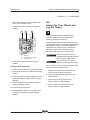
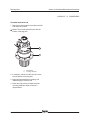
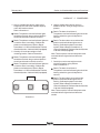
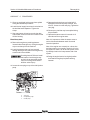
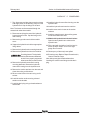
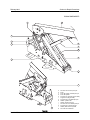
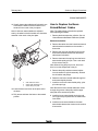
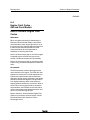
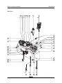
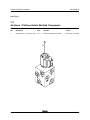
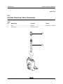
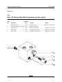
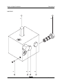
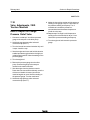
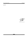
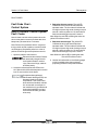
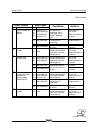
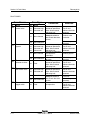
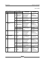
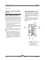
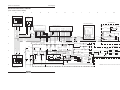
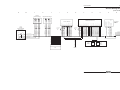
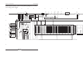
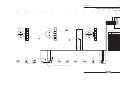
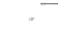
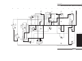
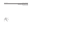
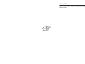
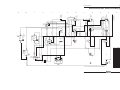
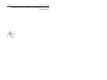
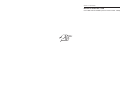
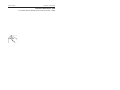
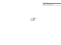
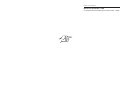
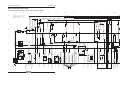
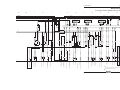
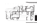
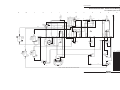
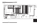
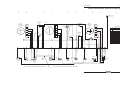
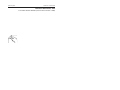
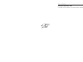
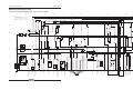
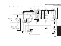
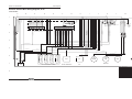
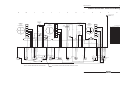
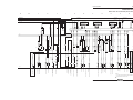
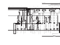
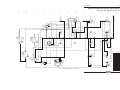
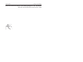
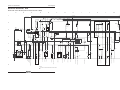
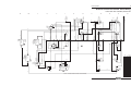
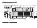
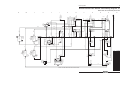
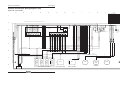
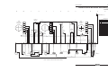
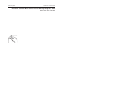
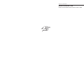
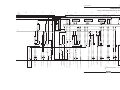
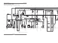
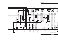
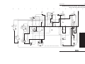
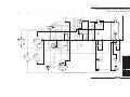
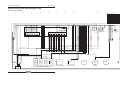
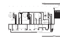
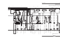
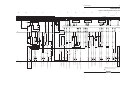
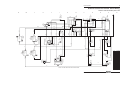
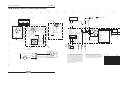
Drive Oil Diverter Manifold Components (welder option)
The oil diverter manifold is mounted to the hydraulic generator located in the engine compartment.
Index
No.
Description
1
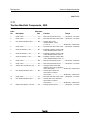
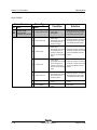
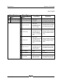
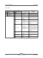
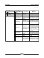
Directional Valve ............................ CU ........... Diverter valve ............................... 80-90 ft-lbs / 108-122 Nm
Schematic
Item
Function
Torque
2
Orifice disc, 0.030 inch / 0.080 cm . CV ........... Delays shift to drive
3
Solenoid valve ............................... CW .......... Pilot valve to diverter ....................... 35-40 ft-lbs / 47-54 Nm
4
Relief valve .................................... CX ........... Charge pressure circuit ................... 35-40 ft-lbs / 47-54 Nm
5
Check valve .................................... CY ........... Prevents oil to generator ................. 35-40 ft-lbs / 47-54 Nm
5
CY
CU
CV
CW
CX
4 - 60
S-60 • S-65 • S-60 HC
1
2
3
4
Part No. 77828