1
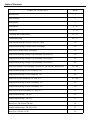
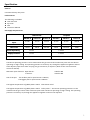
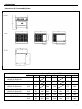
Thor Gas Oven Technical Service Manual Model: GH100-P, GH100-N, GH101-P, GH101-N , GH102-P, GH102-N IMPORTANT FOR FUTURE REFERENCE Please complete this information and retain this manual for the life of the equipment. For Warranty Service and/or parts, this information is required. Model Number Serial Number Date Purchased WARNING: For your safety, do not store or use gasoline or other flammable vapors or liquids in the vicinity of this or any other appliances. Keep the area free and clear of combustible. WARNING:Improper installation, adjustment, alteration, service or maintenance can cause property damage, injury, or death. Read the installation operating and maintenance instructions thoroughly before installing, or servicing this equipment. WARNING:Instructions must be posted in a prominent location. All safety precautions must be taken in the event the user smells gas. Safety information can be obtained from your local gas supplier. 15 Badgally Road, Campbelltown NSW 2560 Table of Contents TABLE OF CONTENTS PAGE Introduction 1 Specification 2 Dimensions 3 Installation 4~8 Operation 9 ~ 11 Cleaning and Maintenance 12 ~ 13 Troubleshooting 14 ~ 37 Conversion from NG to LPG and vice-versa 36 Explosion Drawing (Griddle Plate Assembly) 38 Parts List (Griddle Plate Assembly) 39 Explosion Drawing (Range Top Assembly TR-HP12F) 40 Explosion Drawing (Range Top Assembly TR-HP24F) 41 Explosion Drawing (Range Top Assembly TR-HP36F) 42 Parts List (Range Top Assembly TR-HP12F, TR-HP24F, TR-HP36F) 43 ~ 44 Explosion Drawing (Oven Assembly 24”) 45 Explosion Drawing (Oven Assembly 36”) 46 Parts List (Oven Assembly 24” and 36”) 47 ~ 48 Explosion Drawing (Frame Assembly 24”) 49 Explosion Drawing (Frame Assembly 36”) 50 Parts List (Frame Assembly 24” and 36”) 51 Explosion Drawing (TR-4F) 52 Explosion Drawing (TR-6F) 53 Parts List (TR-4F and TR-6F) 54 Explosion Drawing (TR-4F-G12F) 55 Parts List (TR-4F-G12F) 56 Introduction We are confident that you will be delighted with your Thor Gas Oven, and it will become a most valued appliance in your commercial kitchen. To ensure you receive the utmost benefit from your new Gas Oven, there are two important things you can do. Firstly: Please read the instruction book carefully and follow the directions given. The time taken will be well spent. Secondly: If you are unsure of any aspect of the installation, instructions or performance of your appliance, contact your dealer promptly. In many cases a phone call could answer your question. CE Only: These instructions are only valid if the country code appears on the appliance. If the code does not appear on the appliance, refer to the supplier of this appliance to obtain the technical instructions for adapting the appliance to the conditions for use in that country. WARNING: IMPROPER INSTALLATION, ADJUSTMENT, ALTERATION, SERVICE OR MAINTENANCE CAN CAUSE PROPERTY DAMAGE, INJURY OR DEATH. READ THE INSTALLATION, OPERATING AND MAINTENANCE INSTRUCTIONS THOROUGHLY BEFORE INSTALLING OR SERVICING THIS APPLIANCE. WARNING: INSTRUCTIONS TO BE FOLLOWED IN THE EVENT THE USER SMELLS GAS ARE TO BE POSTED IN A PROMINENT LOCATION. THIS INFORMATION SHALL BE OBTAINED BY CONSULTING THE LOCAL GAS SUPPLIER. WARNING: GREAT CARE MUST BE TAKEN BY THE OPERATOR TO USE THE EQUIPMENT SAFELY TO GUARD IT AGAINST RISK OF FIRE. • THE APPLIANCE MUST NOT BE LEFT ON UNATTENDED. • IT IS RECOMMENDED THAT A REGULAR INSPECTION IS MADE BY A COMPETENT SERVICE PERSON TO ENSURE CORRECT AND SAFE OPERATION OF YOUR APPLIANCE IS MAINTAINED. • DO NOT STORE OR USE GASOLINE OR OTHER FLAMMABLE VAPOURS OR LIQUIDS IN THE VICINITY OF THIS OR ANY OTHER APPLIANCE. • DO NOT SPRAY AEROSOLS IN THE VICINITY OF THIS APPLIANCE WHILE IT IS IN OPERATION. WARNING: THIS APPLIANCE IS; • FOR PROFESSIONAL USE AND IS TO BE USED BY QUALIFIED PERSONS ONLY. • ONLY QUALIFIED SERVICE PERSONS ARE TO CARRY OUT INSTALLATION, SERVICING AND GAS CONVERSION OPERATIONS. • COMPONENTS HAVING ADJUSTMENTS PROTECTED BY THE MANUFACTURER SHOULD NOT BE ADJUSTED BY THE USER/OPERATOR. • DO NOT OPERATE THE APPLIANCE WITHOUT THE LEGS SUPPLIED FITTED. 1 Specification General Commercial heavy duty oven. Pack Contents The following is included: Thor Gas Oven 2pc racks Feet Instruction Manual Gas Supply Requirements Natural Gas Propane GH100-N GH101-N GH102-N GH100-P GH101-P GH102-P Single burner Heat Input 32.5 MJ 32.5 MJ 32.5 MJ 32.5 MJ 32.5 MJ 32.5 MJ Oven burner 25MJ 25MJ 25MJ 28MJ 32.5 MJ 32.5 MJ Heat Total 155 MJ 220 MJ 187.5MJ 158 MJ 227.5 MJ 195MJ Burner Operating 1.0 kPa 2.75 kPa Supply Pressure 1.0 kPa 2.75 kPa Gas Connection ¾” BSP Male ¾” BSP Male The burner operating pressure is to be measured at the gas control valve outlet test point with two burner operating at ‘High’ setting. The operating pressure is ex-factory set, through the appliance regulator and not to be adjusted, apart from when carrying out gas conversion, if required. (Refer to the ‘Gas Conversion’ section for details). Minimum input of burner: Open burner: ‘U’ burner: Size of the pan: 23MJ for NG 21MJ for NG The smallest pan for open burner is 100mm; The biggest pan for open burner is 300mm. The highest temperature of griddle plate is 290℃(thermostat value) The highest temperature of griddle plate is 390℃(safety value).The burner operating pressure is to be measured at the gas control valve outlet test point with one burner operating at ‘High’ setting. The operating pressure is ex-factory set, through the appliance regulator and not to be adjusted. 2 Dimensions Dimensions for Freestanding Oven Views Model Number Exterior Dimensions (Millimeters) A 610 B 835 TR-G24F(T) 610 TR-6(F) GH101-P / GH101-N TR-4(F)-G12F(T) GH102-P / GH102-N TR-4(F) GH100-P / GH100-N TR-2(F)-G24F(T) TR-G36F (T) C D 680 E 750 835 680 915 835 915 835 915 915 F H 1175 L 940 750 1175 940 680 750 1175 940 305 680 750 510 1175 940 835 610 680 750 510 1175 940 835 915 680 750 510 1175 940 3 Installation Installation Requirements NOTE: • It is most important that this appliance is installed correctly and that operation is correct before use. Installation shall comply with local gas, health and safety requirements. • This appliance shall be installed with sufficient ventilation to prevent the occurrence of unacceptable concentrations of substances harmful to health. Our Gas Ovens are designed to provide years of satisfactory service and correct installation is essential to achieve the best performance, efficiency and trouble-free operation. This appliance must be installed in accordance with National installation codes and in addition, in accordance with relevant National / Local codes covering gas and fire safety. Australia: AS 5601/AG 601 (to be AS 5601)- Gas Installations New Zealand: NZS 5261 - Gas Installation. United Kingdom: Gas Safety (Installation and Use) Regulations 1998 BS 6173-Installation of Catering Appliances. BS 5440-1&2 Installation Flueing & Ventilation. Ireland: IS 820-Non Domestic Gas Installations. Installations must be carried out by qualified persons only. Failure to install equipment to the relevant codes and manufacturer’s specifications shown in this section will void the warranty. Components having adjustments protected by the manufacturer are only to be adjusted by an authorized service agent. They are not to be adjusted by the installation person. Step 1: Unpacking IMMEDIATELY INSPECT FOR SHIPPING DAMAGE All containers should be examined for damage before and during unloading. The freight carrier has assumed responsibility for its safe transit and delivery. If damaged equipment is received, either apparent or concealed, a claim must be made with the delivering carrier. Apparent damage or loss must be noted on the freight bill at the time of delivery. The freight bill must then be signed by the carrier representative (Driver). If the bill is not signed, the carrier may refuse the claim. The carrier can supply the necessary forms. A request for inspection must be made to the carrier within 15 days if there is connected damage or loss that is not apparent until after the equipment is uncreated. The carrier should arrange an inspection. Be certain to hold all contents plus all packing material. 4 Installation 1. 2. 3. 4. Cut banding straps and remove corrugated box from range. Cut banding strap holding range to wooden skid. Lift the flue riser off the front of the skid and set it aside. Pull the shelf assembly out from under the base and set it aside. Step 2a: Install the Legs A set of four legs is packed with units ordered with legs. (For units ordered with casters (option), go to step 2b). A threaded leg pad is fastened to the base frame at each corner. Each leg has a corresponding mating thread. The leg can be adjusted to overcome a slightly uneven floor. 1. 2. 3. 4. 5. 6. Raise unit sufficiently to allow leg pads and legs to be attached. For safety, “shore up” and support the unit with an adequate blocking arrangement strong enough to support the load. Attach the four leg pads to the bottom of the range using the lock washers and machine screws. The mounting holes are pre-drilled and threaded. Screw the legs into the holes in the centers of the leg pads. Lower unit gently onto a level surface. Never drop or allow the unit to fall. Use a level to make sure that the range surface is level. The legs can be screwed in or out to lower or raise each corner of the range. Go on to installation Step 3. 5 Installation Step 2b: Install Casters (options) A set of four casters is packed with units ordered with casters (instead of legs). A threaded leg pad is fastened to the base frame at each corner. Each caster gas a corresponding mating thread. The caster can be adjusted to overcome a slightly uneven floor. Casters are provided with a Zerk fitting for proper lubrication when required. Raise unit sufficiently to allow leg pads and casters to be attached. For safety, “shore up” and support the unit with an adequate blocking arrangement strong enough to support the load. Attach the four leg pads to the bottom of the range using the lock washers and machine screws. The mounting holes are pre-drilled and threaded. Screw the caster into the holes in the centers of the leg pads. Install the casters that have a locking brake under the front of the unit. Lower unit gently onto a level surface. Never drop or allow the unit to fall. Use a level to make sure that the range surface is level. The casters can be screwed in or out to lower or raise each corner of the range. After the unit has been leveled, tighten the lock nuts. Secure the restraining-device bracket to a wall stud located as close as possible to the appliance connector inlet and outlet connections. Use four screws. NOTICE Adequate means must be provided to limit the movement of the appliance without depending on the connector and the quick-disconnect device or its associated piping to limit the appliance movement. The restraining means should be attached to a frame member on the back of the unit. 6 Installation Step 3: Attach Flue Riser Place the flue riser assembly on the range as shown on the appropriate diagram below. Slide the flue riser assembly over the bayonets until it bottom out, as shown below. Secure ends of flue riser assembly with two M6 hex head bolts, flat washers and lock-washers Single-Oven Models Location 1. 2. 3. 4. 5. 6. Installation must allow for a sufficient flow of fresh air for the combustion air supply. Installation must include adequate ventilation means, to prevent dangerous build-up of combustion products. Any gas burning appliance requires adequate clearance and ventilation for optimum and trouble-free operation. The minimum installation clearances shown below are to be adhered to. Position the appliance in its approximate working position. All air for burner combustion is supplied from underneath the unit. The legs must always be fitted and no obstructions placed on the underside or around the base of the unit, as obstructions will cause incorrect operation and / or failure of the appliance. Components having adjustments protected by manufacturer are only allowed to be adjusted by an authorized service agent. They are not to be adjusted by the installation person. Clearances NOTE: Only non-combustible materials can be used in close proximity to this appliance. Combustible Surface Non Combustible Surface Left / Right Hand Side 355mm 0mm Rear 250mm 0mm Assembly NOTE: • This appliance is assembled before delivery except feet. • This appliance is fitted with adjustable feet to enable the appliance to be positioned securely and level. This should be carried out on completion of the gas connection. Refer to the ‘Gas Connection’ section. • IM will be stated that the appliance shall be installed in such a way that side body surfaces are not accessible in the installed position. 7 Installation Gas Connection NOTE: ALL GAS FITTING MUST ONLY BE CARRIED OUT BY A QUALIFIED PERSON. 1. 2. The Gas Ovens do not require an electrical connection, as they function totally on the gas supply only. It is essential that the gas supply is correct for the appliance to be installed and that adequate supply pressure and volume are available. The following checks should therefore be made before installation:a. Gas Type required for the appliance is shown in the rating label. Check that this is correct for the gas supply the appliance is being installed for. The gas conversion procedure is detailed in this manual page 33. b. Supply Pressure required for this appliance is shown in the ‘Gas supply requirements’ section of this manual. Check the gas supply to ensure adequate supply pressure exists. c. Input Rate of this appliance is stated on the Rating label .The input rate should be checked against the available gas supply line capacity. Particular note should be taken if the appliance is being added to an existing installation. NOTE: It is important that adequately sized piping runs directly to the connection joint on the appliance with as few tees and elbows as possible to give maximum supply volume. NOTE: Ensure the regulator is converted to the correct gas type that the appliance will operate on. The regulator outlet pressure is fixed ex-factory for the gas type . 3. Correctly locate the appliance into its final operating position and using a spirit level, adjust the legs so that the unit is level and at the correct height. Connect the gas supply to the appliance through the regulator. A suitable jointing compound which resists the breakdown action of propane must be used on every gas line connection, unless compression fittings are used. Check all gas connections for leakages. 4. 5. WARNING: DO NOT USE A NAKED FLAME TO CHECK FOR GAS LEAKAGES. 6. 7. 8. 9. Check that the gas operating pressure. Turn off the mains gas supply and bleed the gas out of the appliance gas lines. Turn on the gas supply and the appliance. Verify the operating pressure remains correct. Commissioning 1. Before leaving the new installation; a. Check the following functions in accordance with the operating instructions specified in the ‘Operation’ section of this manual. • Light the Pilot Burner. • Light the Main Burner. • Turning 'Off' the Main Burner/Pilot. b. Ensure that the operator has been instructed in the areas of correct lighting, operation, and shutdown procedure for the appliance. 2. This manual must be kept by the owner for future reference and a record of the Date of Purchase, Date of Installation and the Serial Number of the Appliance must be recorded and kept with this manual. (These details can be found on the Rating label, refer to the ‘Gas Connection’ section). NOTE: If for some reason it is not possible to get the appliance to operate correctly, shut off the gas supply and contact the supplier of this appliance. 8 Operation Operation Guide CAUTION: • THIS APPLIANCE IS FOR PROFESSIONAL USE AND IS ONLY TO BE USED BY QUALIFIED PEOPLE. • ONLY QUALIFIED SERVICE PERSONS ARE TO CARRY OUT INSTALLATION, SERVICING OR GAS CONVERSION OPERATIONS. • COMPONENTS HAVING ADJUSTMENTS PROTECTED (E.G. PAINT SEALED) BY THE MANUFACTURER SHOULD NOT BE ADJUSTED BY THE USER/OPERATOR. 1. 2. The Gas Ovens have been designed to provide simplicity of operation and 100% safety protection. Improper operation is therefore almost impossible, however bad operation practices can reduce the life of the range top oven and produce a poor quality product. To use this appliance correctly please read the following sections carefully: Lighting the Top Burners. Turning off the Top Burners / Pilots. Lighting the Oven. 9 Operation WARNING: SURFACE TEMPERATURE OF THE GRIDDLE CAN REACH OVER 300°C WHEN THE APPLIANCE IS OPERATED AT FULL SETTING. 1. Lighting the Top Burners The burners are fitted with individual standing pilots which allows the main burners to be turned ONOFF without the need to manually re-light the burner each time that it is turned ON, as the burner will be automatically lit itself by the pilot burner. Flame Failure Protection is incorporated for each burner by way of a thermo-electric system which will shut off the gas supply to that burner in the event that the burner goes out, so that un-burnt gas is not expelled. 1. Select the burner required, depress and turn the corresponding gas control knob anti-clockwise to the ‘PILOT’ position. 2. With the gas control knob depressed, manually light the pilot burner or use the piezo igniter provided (optional). 3. Release the gas control knob after approximately 10-20 seconds after lighting the pilot burner. 4. The pilot burner should stay alight - if not, repeat Steps (b. to c. above.) 5. ‘Full Flame’ can now be achieved by depressing and rotating the gas control knob anti-clockwise to the first stop 'HIGH' flame position. 6. Low flame can be achieved by depressing the gas control knob and rotating fully anti-clockwise to the ‘LOW' flame position. 7. To achieve simmer control, depress the gas control knob and rotate between the ‘HIGH’ and ‘LOW’ positions to achieve the temperature required. 2. Turning 'OFF' the Main Burners / Pilots 1. To turn off the main burner, but keep the pilot burner alight, rotate the gas control knob to the 'PILOT' position. The main burner will extinguish and the pilot will remain alight. 2. To turn off the 'PILOT', depress and turn the gas control knob clockwise back to the ‘┃’ position. The 'PILOT' burner will extinguish. Lighting Oven The oven is controlled by a knob on the front control panel. To light the pilot of an oven, do the following: 1. 2. 3. 4. Turn oven thermostat to “Pilot” position. Depress the gas control knob. Light the pilot. Hold in the gas control knob for approximately 10-20 seconds, then release. The pilot flame will be established. 10 Operation Main burner air supply: 1. For efficient burner operation, a proper balance of gas volume and primary air supply must be maintained which will result in complete combustion. Insufficient air supply results in a yellow streaming flame. Primary air supply is controlled by an air shutter on the front of the burner. 2. Loosen the screws on the front of the burner and adjust the air shutter to just eliminate the yellow tips of the burner flame. Lock the air shutter in place by tightening the screws. CAUTION The space between the legs at the bottom admits combustion air. DO NOT BLOCK THIS SPACE. All burners are lit from constantly burning pilots. Turning the valve to the desired flame height is all that is required to put the unit in service. Do not permit fans to blow directly at the unit. Wherever possible, avoid open windows next to the units' sides or back. Avoid wall type fans which create air cross-currents within a room. It is also necessary that sufficient air should be allowed to enter the room to compensate for the amount of air removed by any ventilating system. Otherwise, a subnormal atmospheric pressure will occur, affecting operation and causing undesirable working conditions. A properly designed and installed hood will act as the heart of the ventilation system for the room or area in which the unit is installed, and will leave the unit independent of changing draft conditions. All valves must be checked and lubricated periodically. This must be done by an authorized service representative in your area. Note: Please wait at least 15 seconds to restart the main burners to maintain the best function of the thermostat valve after turning off the main burners. IMPORTANT Should any abnormal operation like; - ignition problems, - abnormal burner flame, - burner control problems, - partial or full loss of burner flame in normal operation, be noticed, the appliance requires IMMEDIATE service by a qualified service person and should not be used until such service is carried out. 11 Cleaning and Maintenance CAUTION: Always turn off the gas supply before cleaning. This appliance is not water proof. Do not use water jet spray to clean this appliance. NOTE: Parts protected by the manufacturer or his agent are not to be adjusted by the installer, unless installer is an authorized service agent. the INITIAL CLEANING: Prior to operating your new oven, thoroughly wash the exterior with a mild detergent or soap solution. Do not use abrasive cleaners, since this might damage the cabinet finish. If the stainless steel surfaces become discolored, scrub by rubbing only in the direction of the finished grain. When the oven is first heated, it will smoke until oil used in manufacturing, preservation and dust from storage and shipping are burned off. An hour at "max." on all burners is usually sufficient. DAILY CLEANING: Remove, empty, and clean grease drawers and dirt trays. Clean griddle drain chutes. VENT SYSTEM At least twice a year the unit venting system should be examined and cleaned. Following daily and periodic maintenance procedures will enhance long life for your equipment. Climatic conditions (such as salt air) may require more thorough and frequent cleaning or the life of the equipment could be adversely affected. STAINLESS STEEL SURFACES To remove normal dirt, grease and product residue from stainless steel that operates at LOW temperature, use ordinary soap and water (with or without detergent) applied with a sponge or cloth. Dry thoroughly with a clean cloth. To remove grease and food splatter, or condensed vapors, that have BAKED on the equipment, apply cleanser to a damp cloth or sponge and rub cleanser on the metal in the direction of the polishing lines or metal grains, so as not to leave any mark on the finish of the stainless steel. NEVER RUB WITH A CIRCULAR MOTION. Soil and burnt deposits which do not respond to the above procedure can usually be removed by rubbing the surface with SCOTCH-BERITE scouring pads or STAINLESS scouring pads. DO NOT USE ORDINARY STEEL WOOL, as any particles left on the surface will rust and further spoil the appearance of the finish. NEVER USE A WIRE BRUSH, STEEL SCOURING PADS (EXCEPT STAINLESS), SCRAPPER, FILE OR OTHER STEEL TOOLS. Surfaces which are marred, collect dirt more rapidly and become more difficult to clean. Marring also increases the possibility of corrosion attack. Refinishing may then be required. To remove heat tint- Darkened areas sometimes appear on stainless steel surfaces where the area has been subjected to excessive heat. These darkened areas are caused by thickening of the protective surface of the stainless steel and are not harmful. Heat tint can normally be removed by the foregoing, but tint which does not respond to this procedure calls for a vigorous scouring in the direction of the polish lines, using SCOTCH-BRITE scouring pads or a STANILESS scouring pad in combination with a powered cleanser. Heat tint action may be lessened by not applying, or by reducing heat to equipment during slack periods. BURNERS- GENERAL Little attention is needed, but if spillage should occur, it may be necessary to clean around pilot areas, air mixer and under burners. Use a wire brush if necessary. Periodically, burners (particularly open top type) should be removed and cleaned. Allow interior to drain. Dry thoroughly before re-installing. HOT TOPS Allow range to cool. If water is used on tops while still hot, they may crack. Avoid this practice. Remove tops from range and clean surfaces with hot water and detergent. A wire brush may be used on the underside of the hot pot plate. It is recommended not to clean tops while still on range, even if cooled, as excessive water will drip into the burner box and deteriorate the metal. 12 Cleaning and Maintenance Do not waste gas and abuse equipment by leaving all burners “FULL ON”, if not required. During idling periods, adjust burner valves to keep top warm. Re-adjust burner valves as required for periods of heavy loads. CARE OF GRIDDLES New griddles should be carefully tempered and cared for in order to avoid possible damage. To break in a new griddle, first wipe it clean. Next, light all the griddle burners and turn them to low for one hour. Then gradually bring each griddle up to frying temperature. Next, spread three or four ounces of beef suet, or as a substitute, baking soda, to season it. Never allow water on a hot griddle and never wash it with soap and water. Use a Norton Alundum Griddle Brick to clean the griddle. Always remember to heat griddle slowly because quick heat may cause costly damage. Griddle plates cannot be guaranteed against damage due to carelessness. Never place utensils on griddle. Do not overheat griddle above 575F (300℃), as this will cause warpage or breakage. Do not use any type of steel wool. Small particles may be left on the surface and get into food products. Do not clean spatula by hitting the edge on the griddle plate. Such action will only cut and pit the griddle plate, leaving it rough and hard to clean. Do not waste gas or abuse equipment by leaving valves at “FULL ON” position or thermostat at high temperature if not required. During idle periods, set valves at “LOW” position or thermostat to low temperature settings to keep griddle warm. Reset valves or thermostats, as required, for periods of heavy load. Turn valves or thermostat to “OFF” at the end of daily operation. OPEN TOP PLATE Remove enameled top plate and spiders, clean with a solution of hot water and strong soap or detergent. The area around the charge port, where the splash tube is attached to the burner, must be free from any spillage or residue, or other obstructions. The splash tubes must be clean and properly aligned with the pilot housing to insure good top burner ignition. Pilot should be 12 to 15mm blue flame. Avoid carbon producing tip or unstable blowing or lifting of flame. OVEN INTERIOR Allow oven to cool. Remove porcelain enameled oven bottom. Clean by rubbing with strong detergent and Brillo pad or similar scrubber. “Spill-over” should be cleaned from the bottom as soon as possible to prevent carbonizing and a “burnt-on” condition. For stubborn accumulations, commercial oven cleaners are recommended. The porcelain oven door lining can be cleaned in a similar manner. The side, rear and top lining should be wiped only with a cloth dampened with a mild detergent and water. Avoiding using excessive amounts of water, as this may drip into burner compartment and deteriorate the metal in that area. Do not use strong commercial cleaners or abrasive pads on the side, rear or top linings, as they may damage the finish or leave gray residue. NOTE: • If the gas Oven usage is very high, we recommend that the weekly cleaning procedure is carried out on a more frequent basis. • Ensure that protective gloves are worn during the cleaning process. • DO NOT use harsh abrasive detergents, strong solvents or caustic detergents as they will damage the grate and burners. • DO NOT use water on the cooking grid while they are still hot as warping may occur. Allow these items castings to cool and remove for cleaning. • Parts protected by the manufacturer or his agent are not to be adjusted by the installer, unless the installer is an authorized service agent. 13 Trouble shooting Periodic Maintenance NOTE: All maintenance operations should only be carried out by a qualified service person. To achieve the best results cleaning must be regular and thorough and all controls and mechanical parts should be checked and adjusted periodically by a qualified service person. If any small faults occur, have them attended to promptly. Don't wait until they cause a complete breakdown. Trouble shooting This section provides an easy reference guide to the more common problems that may occur during the operation of your equipment. The fault finding guide in this section is intended to help you correct, or at least accurately diagnose problems with your equipment. Although this section covers the most common problems reported, you may encounter a problem not covered in this section. In such instances, please contact your local authorized service agent who will make every effort to help you identify and resolve the problem. Please note that the service agent will require the following information: • The Model Trade Name and the Serial Number of the Appliance. (Both of them can be found on the Rating label located on the appliance. GENERAL INFORMATION BURNING SPEED: The velocity at which flame travels through an air-gas mixture. Burning speeds vary with types of gases, and the amount of air mixed with the gas. This air to gas ratio is very important in that it is directly related to flame stability. PRODUCTS OF COMBUSTION: Carbon dioxide and water vapor is formed in burning plus the nitrogen in the reactants that entered with the combustion air. FLUE PRODUCTS: The combination of combustion and excess air leaving the combustion area. Since water is produced as a vapor in the burning of gas it is also present in flue products. If the flue products and vent system remain hot enough this vapor is harmlessly discharged. If not, the vapor can reach the dew point and condense into water which can accumulate in the system. INCOMPLETE COMBUSTION: A poorly vented appliance restricts flow of air into an appliance. Lack of ventilation around an appliance may lower oxygen content in the surrounding air. This can be a result of spillage of combustion products into the room as well. These conditions can cause incomplete combustion and poor performance of an appliance. Adequate, but not excessive ventilation is a must and cannot be over emphasized. PRIMARY AIR: That air which is mixed with gas before the gas leaves the burner port to burn. Ideal burning condition generally is 10 cubic feet of air per cubic foot of gas. SECONDARY AIR: The remaining air needed for complete combustion besides primary air. This is the air surrounding the flames. 14 Trouble shooting FLAME STABILITY: Primary air, burning speed, port size and port depth are several factors affecting flame stability. Flames on a burner tend to stabilize at a point where flow velocity out and burning speed back are equal. This balance of flow velocities and burning speed explain why flames change when primary air or gas rate is adjusted. B.T.U.: British Thermal Units is the heat energy produced when burning a fuel gas. One BTU of heat will raise the temperature of one pound of fresh water one degree Fahrenheit. BURNER PROBLEMS LIFTING BURNER FLAMES: Excessive primary air can cause flames to lift and blow off the burner ports which can be noisy as well as inefficient. More importantly however is the production of dangerous carbon monoxide under this condition. Any factor which reduces burning speed promotes lifting flames. Also, any factor which increases flow velocity from ports contributes to lifting flames. Overrating of burners is also a cause. The normal cure for lifting flames is the reduction of primary air input to the burner. FLASHBACK: Flashback occurs when gas-air flow velocity is less than burning speed at some point near a burner port. Flash back is a condition where gas ignites within the burner. Any factor which increases burning speed tends to promote flashback, and any factor decreasing flow velocity from the ports will contribute to flashback. Flashback is more prevalent with faster burning gases. Natural gas is relatively slow burning gas hence flashback is less likely. Reducing primary air is the usual cure for flashback. EXTINCTION POP: This is merely flashback occurring when a burner is turned off. It is usually instantaneous although it can occur several seconds after the burner has been turned off. What happens is that primary air continues to flow into the burner even though the gas jet has been cut off and does not inject air. The mixture in the burner changes from the normal operating mixture to all air and flow rate through the ports falls off toward zero. Under these conditions, it is possible for the flame speed to exceed flow velocity at some instant and flashback may occur. The result is a tiny explosion or pop. Since increasing primary air increases the burning speed, it is obvious that reducing primary air input will reduce the flashback tendency. FLUCTUATING FLAMES: Length of burner flames may fluctuate or shorten over a period of time with no re-adjustments of the burner. This condition usually indicates a non-uniform gas pressure at the orifice. Fluctuating flames usually do not create any immediate problems, such as incomplete combustion, unless flames impinge on cool surfaces. This condition should be corrected, however, since it warns of possible future problems. Unsteady gas pressures cause flames to fluctuate. Usually this condition indicates problems with the gas pressure regulator, the gas meter or other gas supply problems. Check the orifice for blockage by dust or dirt from supply lines. Very small pilot orifices are quite prone to blockage. Occasionally, too much grease in pilot valves restricts gas flow to pilot burners. Remove any excess greases. 15 Trouble shooting YELLOW TIPPING OF FLAMES: Too severe a reduction in primary air also causes its problems. Yellow tipping is one of them. Flames will eventually become all yellow if no primary air is supplied. These yellow tips are caused by glowing carbon particles in the flame. Soot will form if these yellow flames impinge on cooler surfaces. Here again carbon monoxide can be produced. Yellow tipping is corrected by the injection of more primary air. FLAME ROLLOUT: When the condition known as flame rollout occurs, flames roll out of the combustion chamber openings when the burner is turned ON. Flame rollout may create a fire hazard, or scorch appliance finishes, burn wire, or damage controls. The gas in the burner mixer may be ignited, producing flashback. Flame rollout is actually a variation of floating flames, with flames reaching for air outside the combustion chamber. Again, the basic cause is a lack of combustion air. This lack of air may be due to overrating of burners, poor draft or blockage of flueways. Apply the corrections for these problems listed for floating flames. Some appliances use step-type controls. These controls limit initial gas flow to the burner to establish natural draft in the appliance before full gas rate is allowed to flow. Check the operation of this control, and replace the control if it is faulty. FLOATING FLAMES: The difference between floating flames and lifting (or blowing) flames should be clearly understood. Both conditions are undesirable, but the causes and corrective steps are different. Floating flames are lazy looking. They do not have well defined cones, and appear to be “reaching” for the air. They are long, illdefined, quite flames which roll around in the combustion chamber sometimes completely off the ports. Usually a strong aldehyde odor is present. Floating flames almost always indicate incomplete combustion. They point to a dangerous condition which require prompt correction. If secondary air supply is reduced too far burner flames will float. Combustion products above the burner re-circulate lower in the chamber. These products contaminate the air supply, adding to the problem. A lack of combustion air causes burner flames to float. Several conditions, or a combination of these conditions can be the cause. The appliance may be overrated. If so, the flue outlet area provided for the rated input may be too small for the increase gas rate. Check appliance rate and reduce if necessary. Other conditions may cause poor venting and lead to floating flames. Soot or dust may be blocking flueways. Check flueways and clear any blockage found. Determine, if possible, the reason the flueways blocked up. Check for blockage of burners, and clean them if necessary. Adjust primary air to get rid of any yellow tipping which may have produced soot to block he flueways. Make sure secondary air inlet openings are not blocked. Reduced natural draft (venting) through an appliance may take place when it is operated from a cold start. Some floating flames may appear for a brief time until draft is established. When the appliance heats up it should operate in a normal manner. UNSTABLE OR WAVERING FLAMES: Drafts across burners may cause flames to waver or appear to be unstable. This condition should not be confused with lifting or floating flames. Wavering burner flames can lead to incomplete burning if flames impinge on cool surfaces. Pilot flames under drafts may go out, or they may be diverted from heating the sensing element of the automatic pilot device. In either case the automatic pilot will shut off gas supply to the appliance. Drafts affecting pilot flames may be simply external drafts, such as across the floor. Protect the pilot flames with suitable baffles. Draft-blown main burner flames may indicate a more serious problem, such as cracked heat exchanger. Replace or repair a cracked heat exchanger without delay. 16 Trouble shooting GAS ODOR AT PRIMARY AIR OPENINGS: Under normal burner operation, a negative pressure (vacuum) should exist inside the primary air openings of a burner, drawing in air. If all gas fed to the burner by the orifice does not flow to the burner head, some gas may spill from the primary air openings. If this condition is found, check the burner body for restrictions, and check the orifice to make certain it is not out of line. CORROSION OF APPLIANCES: Gas appliances are designed and built to give long dependable service life. In some installations recently, usually severe corrosion has occurred resulting in customer complaints. This corrosion is attributed to the extensive use of aerosol propellants, hydrocarbons which contain the elements FLOURINE AND CHLORINE. These elements are called halogens. Halogens in their free state are very corrosive. When the propellants pass through a flame, they break down and the halogen gases are released. In combination with the water vapor in the flue gases they cause corrosion in heat exchangers, flueways and other appliance parts. Some of the worst cases of this corrosion have been in beauty shops where hair sprays are used and in dry cleaning plants where halogen-containing materials are used as cleaning fluids. TROUBLESHOOTING RANGE TOP BURNERS Consult the following table and the flowchart that begins on the following page. Problem Look for- All burners and pilots in unit will not turn on - Main gas supply to unit is “OFF”. All burners produce excessive carbon deposits - Incorrect gas type supplied to unit. -Incorrect supply pressure Only some burners in a unit produce excessive Carbon deposits -Incorrect orifices. - Primary air not adjusted properly. Only some pilots produce excessive carbon Deposits -pilot gas not adjusted properly. Top burner (not oven) will not come on Top section pilot will not stay ignited - Safety valve for top burner in “OFF” position. -Pilot out -Clogged orifice -Draft condition -Improper ventilation system. -Air in gas line. 17 Trouble shooting RANGE TOP BURNER TROUBLESHOOTING Common checks of all top configurations. NOTE: Griddle Tops Check that the burners are set level in the support brackets. NOTE: Griddles and Hot Tops must be raised and secured or removed. Check that the burners are clean and all ports are clear. CAUTION! Before raising or removing Griddle Tops. Remove each burner and check that the venture is clean and free of buildup and debris. With each burner removed check that the orifice size is correct and clean and free of buildup and debris. Remove the knobs and carefully lower the top valve cover panel. CAUTION! Wiring attached behind panel on C.O base models. Remove the knobs and carefully lower the control panel. CAUTION! Wiring attached behind panel. Pull the Griddle thermostat bulbs out of the tubes. Light all burners on the range. NOTE: Leave the oven door open. Observe the inlet pressure. Check that each burner valve and orifice is in alignment with the burner Inlet pressures for gases are: See rating label. Shut off the main gas supply. Install a pressure tap in the main gas line before the range pressure regulator and install a manometer. If the inlet pressure is low, all equipment on the main gas line should be lit and the pressure adjusted Turn on the main gas supply. Shut off the range burners and main gas and remove the pressure tap. Re-light all pilots. Continues on next page. 18 Trouble shooting Continued from Previous Page Install the grates or griddle/hot tops. With the gas supply shut off to the range install a pressure tap on the manifold in the Plugged tap provided Install a manometer on the pressure tap. Install the thermostat bulbs into griddle tops. Be sure the capillary tubes are away from burners, flames and excessive heat. Turn on the gas supply to the range. Test each burner. Observe the manifold pressure. Re-light the pilots and turn on all the burners. Manifold pressures are: Natural=1000 Pa Propane= 2750 Pa Each burner should have a steady blue flame on each port of the burner. Propane burners may have a small amount of yellow tipping. This is normal. If the flame is rising up off of the ports adjust the burner shutter closed. If the pressure is low remove the cap from the pressure regulator on the back of the range. If the flame is long and yellow adjust the burner shutter open. Clockwise increases the pressure and counter clockwise decreases the pressure. Shut off the range burners and main gas and remove the pressure tap. NOTE: Griddle Hot Top burners may be long and float when cold. Allow the top to heat before making burner adjustments. Propane burners may have a slight popping noise when turned off .This is normal Replace the pressure tap plug in the manifold. Reinstall the control panel and knobs. Re-light the pilots. 19 Trouble shooting OVEN PILOT DOES NOT WORK Continued to hold the button for 30 seconds. The pilot should light and remain lit after the button is released. Press and hold the button on the oven safety valve and put flame to the pilot. If the pilot doesn’t remain lit, wait 5 minutes and retry. If the pilot doesn’t remain lit remove the thermocouple from the safety valve. Does the pilot burn? NO If the pilot doesn’t burn remove the oven bottom. YES Install a thermocouple adapter between the safety valve and thermocouple to measure the DC MV. Install a DVM on the adaptor. Holding the button, light the pilot. Loosen pilot out of the burner bracket. If the voltage doesn’t rise above 10 MV adjust the pilot valve and retest. Remove pilot tube from the safety valve. Remove the pilot orifice from the pilot or end of the tube and check for debris. Re-install the pilot orifice and tubing. If the MV doesn’t rise quickly above 10 replace the thermocouple. If the thermocouple works properly replace the safety valve. Light the pilot. 20 Trouble shooting THERMOSTAT GRIDDLE TROUBLESHOOTING If the flame is not correct remove the knobs and bezel.. Remove the knobs and control panel. CAUTION! WIRING BEHIND THE PANEL. There is a slotted screw below the stem on the thermostat valve. Turn the screw counter clockwise to establish or increase the flame. Be sure the thermostat bulbs are pushed completely into tubes under the griddle. Put the bezels and knobs on the griddle thermostats. If no flame is established put a soap and water mix to the orifice of the burner to check for gas flow. Set the griddle thermostats to 300F (150℃) If gas is flowing turn the bypass screw until flame is set to specifications. Observe the burners while heating griddle for poor operation. Remove the knobs and bezel and install the control panel. Refer to burner troubleshooting If no flame is established at the bypass setting replace the thermostat. After griddle has heated for approximately 20minutes, observe that the flame has decreased in height. Reinstall the bezels and push out the silver center of the knob from the rear of the knob and reinstall. Set the griddle knobs to the midpoint between the two lines just after the OFF position Set the temperature to 300F°(150℃) and allow the griddle to reheat. This is the bypass setting. Continues on Next Page. Check that there is a 6mm, flame at each port. 21 Trouble shooting Continued from Previous Page Place a digital surface temperature instrument in the center of the griddle. Allow reading to stabilize to 150℃ Repeat this procedure at each burner until the temperature stabilizes to within 30℃ of the set temperature If the temperature cannot be set to within 30℃ replace the thermostat and reset. Record this temperature. Reinstall the silver in the knob center. Move the surface measurement instrument in the center of the griddle over each burner. NOTE: If the user is dissatisfied with the griddle temperature recovery time. Record the temperatures. Turn the bypass screw counter clockwise to fully open the bypass flame. Average the temperature of each burner reading. To adjust the temperature, locate the center of the thermostat. Remove the knobs, bezels and control panel. Scrape the paint seal off of the screw. Reinstall the knobs, bezels and cover panel. NOTE! There are arrows around the screw indicating (H) to increase and (L) to decrease the temperature. Recalibrate the thermostat. NOTE! Only turn this screw by small increments. While holding the knobs at 150 ℃setting, push the screw in and turn it in the direction indicated to change the temperature. NOTE: Components having adjustments protected by the manufacturer, are only allowed to be adjusted by an authorized service agent. They are not to be adjusted by an unqualified service person. 22 Trouble shooting This section provides an easy reference guide to the more common problems that may occur during the operation of your equipment. The fault finding guide in this section is intended to help you correct, or at least accurately diagnose problems with your equipment. Although this section covers the most common problems reported, you may encounter a problem not covered in this section. In such instances, please contact your local authorized service agent who will make every effort to help you identify and resolve the problem. Please note that the service agent will require the following information: • Model Code and the Serial Number of the appliance. (Both of them can be found on the Rating Plate located on the appliance). OPENING OF THE RANGE TOP FOR PARTS REPLACEMENT 1. Remove the trivets. 2. Remove the griddle plate assembly (for TR-4F-G12F model) 3. Remove the control knobs. 4. Remove the thermostat control knob. Loosen the lock screw at the knob side. 5. Remove the griddle drip tray. (for TR-4F-G12F model) 6. Remove the mounting screws of the control panel cover. For TR-4F-G12F model, there are two mounting screws inside the griddle drip tray slot that must be removed to fully remove the control panel cover. 7. Remove the piezo igniter wire. 8. Remove the control rack mounting screws. 9. Remove the control rack. Loosen the thermostat knob lock screw Remove the mounting screws of the control panel (model TR-4F-G12) Remove control rack mounting screws Remove control panel cover Remove control rack Pull-out and remove the range top drip tray 23 Trouble shooting PILOT TROUBLE SHOOTING Fault Pilot won’t light. Pilot goes out when gas control knob released. Possible Cause No gas supply or gas isolation valve is OFF. Remedy Ensure gas isolation valve is turned on, and that gas tanks are not empty. Pilot burner is clogged/blocked. Check the pilot burner if clogged, and clean if necessary. Follow the pilot burner removal procedure. Pilot injector is clogged. Check the pilot injector if clogged, and clean if necessary. Follow the pilot injector removal procedure. Pilot injector is damaged. Check if the pilot injector is blocked/damaged, and replace it if necessary. Follow the pilot injector removal procedure. Releasing the knob before the thermocouple has heated. Hold the knob in for at least 10~20 seconds following ignition of the pilot. Gas pressure too low. Check the pressure of the main line if within standard. Adjust the pressure if necessary. NG – 1.0KPa and LPG – 2.75KPa. Partially blocked pilot injector. Clean the pilot injector or replace the pilot injector if necessary. Follow the pilot injector removal procedure. Thermocouple connection to the gas safety valve is loose. Tighten the thermocouple connection. Faulty thermocouple or FDS. Replace the thermocouple or FDS. Follow the thermocouple removal procedure. Replace the safety gas valve. Follow the safety gas valve removal procedure. Faulty safety gas valve. CHECKING & CLEANING OF THE PILOT INJECTOR: 1. Visually check the orifice of the pilot injector if clogged, damaged or blocked. If it cannot be checked visually, try to blow air in the injector and check if there is air coming out of the orifice. 2. If the orifice is blocked or clogged, use an air blow to remove the clogging. Never pinch the orifice with a pin as this could damage the orifice. 3. If the clogging cannot be removed from the orifice by air blow, replace the injector with a new one. Remember to check the size of the orifice and replace with the same size. 4. Follow the pilot injector removal procedure. THERMOCOUPLE PILOT BURNER ODS MOUNTING SCREWS PILOT INJECTOR PILOT TUBE Disconnecting pilot tube from ODS Assembly’s pilot injector (Rear ODS) 24 Trouble shooting PILOT TROUBLE SHOOTING – cont’d.: RANGE TOP PILOT INJECTOR REMOVAL: 1. Turn-off the pilot. 2. Shut-off the main isolation valve and follow the lock-out/tag-out procedure. 3. Remove the trivets. 4. Remove the burner. 5. Remove the lock nut of the thermocouple. Use 8mm spanner to remove the nut. (Optional for ease of access) 6. Remove the two mounting screws of the FDS. (Optional for ease of access) 7. Disconnect the pilot tube assy. from the pilot injector. Use 13mm spanner to disconnect the fitting. 8. Remove the pilot injector from the FDS Assembly. Use 10mm spanner. Remove the two mounting screws of the FDS Remove the ODS injector from the FDS assembly GRIDDLE TOP ODS INJECTOR REMOVAL: 1. Turn-off the pilot. 2. Shut-off the main isolation valve and follow the lock-out/tag-out procedure. 3. Remove the griddle plate assembly. 4. Disconnect the pilot tube from the ODS injector. Use 13mm spanner to disconnect the fitting. 5. Remove the ODS injector from the FDS. Use 10mm spanner. Replace the ODS injector if necessary. 6. Make sure to check for gas leak, using soap & water, after part installation. ODS INJECTOR PILOT TUBE FITTING Disconnect the pilot tube from the ODS injector. Remove the ODS injector. 25 Trouble shooting PILOT TROUBLE SHOOTING – cont’d.: OVEN PILOT INJECTOR REMOVAL: 1. Turn-off the pilot. 2. Shut-off the main isolation valve and follow the lock-out/tag-out procedure. 3. Remove the two racks and drip tray. 4. Remove the oven burner. 5. Disconnect the pilot tube. Use 13mm spanner to disconnect the fitting. 6. Pull-out to remove the oven pilot injector. Replace the pilot injector if necessary. 7. Make sure to check for gas leak, using soap & water, after part installation. Disconnect the pilot tube PILOT TUBE FITTING Disconnect the pilot tube PILOT INJECTOR Remove the pilot injector 26 Trouble shooting PILOT TROUBLE SHOOTING – cont’d.: RANGE TOP PILOT BURNER REMOVAL: 1. Turn-off the pilot. 2. Shut-off the main isolation valve and follow the lock-out /tag-out procedure. 3. Remove the trivets. 4. Remove the burners. 5. Loosen the screw which locks the pilot burner in place. See FDS assembly photo. 6. Remove the pilot burner by twisting and pulling it out. RANGE TOP THERMOCOUPLE REMOVAL: 1. Turn-off the pilot. 2. Shut-off the main isolation valve and follow the lock-out /tag-out procedure. 3. Remove the trivets. 4. Remove the control panel cover and control rack. Follow the procedure of opening the range top for part replacement in page 20. 5. Disconnect the thermocouple fitting from the safety valve. Use 9mm spanner to loosen the fitting. 6. Remove the lock nut of the thermocouple. Use 8mm spanner to remove the nut. 7. Remove the thermocouple. RANGE TOP FLAME DEVICE SYSTEM ASSEMBLY REMOVAL: 1. Turn-off the pilot. 2. Shut-off the main isolation valve and follow the lock-out/tag-out procedure. 3. Remove the trivets. 4. Remove the burner for ease of access. (Optional) 5. Disconnect the thermocouple fitting from the safety valve. Use 9mm spanner to disconnect the fitting. 6. Disconnect the pilot tube assy. from the ODS injector. Use 13mm spanner. 7. Remove the two mounting screws of the FDS assembly. 8. Remove the Flame Device System (FDS) assembly and replace if necessary. LOCK SCREW PILOT BURNER FDS ASSEMBLY FITTING Disconnect thermocouple fitting which is connected to safety valve ODS Assembly Remove the two mounting screws of the FDS assembly 27 Trouble shooting PILOT TROUBLE SHOOTING – cont’d.: GRIDDLE TOP FDS ASSEMBLY REMOVAL: 1. Turn-off the pilot. 2. Shut-off the main isolation valve and follow the lock-out/tag-out procedure. 3. Remove the griddle plate assembly. 4. Remove the burner. 5. Remove the control panel cover and control rack. Follow the procedure of opening the range top for part replacement in page 20. 6. Disconnect the pilot tube assy. from the ODS injector. Use 13mm spanner to disconnect the fitting. 7. Remove main pipe assy. together with injector fix plate. 8. Disconnect the thermocouple from the safety gas valve. 9. Disconnect the igniter wire from the piezo igniter. 10. Remove the two mounting screws of the FDS assy., then remove the FDS assy., and replace if necessary. 11. Make sure to check for gas leak, using soap & water, after part installation. Remove control panel cover and control rack Remove the griddle plate assy. INJECTOR FIX PLATE MAIN PIPE ASSY. Remove main pipe assy. together with injector fix plate Remove the two mounting screws of the FDS assembly 28 Trouble shooting MAIN BURNER TROUBLE SHOOTING: Fault Possible Cause Remedy Range top burner will not light. No gas supply or gas isolation valve is OFF. Ensure gas isolation valve is turned on, and that gas tanks are not empty. Insufficient gas supply pressure. Adjust the gas supply pressure to required standard. NG – 1.0KPa and LPG – 2.75KPa. Partially blocked injector. Clean the injector or replace the injector if necessary. Follow the main burner injector removal procedure. Faulty safety gas valve. Replace the safety gas valve. Follow the safety gas valve removal procedure. Clogged or blocked gas manifold. Replace the gas manifold. Range top burner low flame setting is too small or too low. Safety gas valve low flame setting is not adjusted to desired flame height. Adjust the low flame setting of the safety gas valve to your desired flame height. Burner flame color is yellow or orange. Insufficient air supply. Adjust the main burner air supply shutter. Wrong type of gas used. Check the name plate and injector’s orifice # used and compare with gas used on the unit. Flame does not come out from Holes are clogged with carbon some of the holes of the burner. or debris. Clean the burner. Carbon builds up on burners Insufficient air supply. Adjust the main burner air supply shutter. Wrong type of gas used. Check the name plate and injector’s orifice # used and compare with gas used on the unit. 29 Trouble shooting MAIN BURNER TROUBLE SHOOTING: RANGE TOP FRONT MAIN BURNER INJECTOR REMOVAL: 1. Turn-off the pilot. 2. Shut-off the main isolation valve and follow the lock-out/tagout procedure. 3. Remove the control panel cover and control rack. Follow the procedure of opening the range top for part replacement in page 20. 4. Disconnect the main pipe assembly fitting at the safety valve. Use 19mm spanner. 5. Remove the main burner injector (FRONT). Use 13mm spanner. 6. Replace the injector if necessary. Remove control rack INJECTOR Main burner injector (FRONT) RANGE TOP REAR MAIN BURNER INJECTOR REMOVAL: 1. Turn-off the pilot. 2. Shut-off the main isolation valve and follow the lockout/tag-out procedure. 3. Remove the trivets. 4. Remove the burner lock screw, then remove the burner. 5. Remove the range top burner injector, and replace if necessary. Use 13mm spanner. Disconnect the main pipe assy. from the safety valve Remove burner lock screw Injector Main burner injector (REAR) 30 Trouble shooting MAIN BURNER TROUBLE SHOOTING: GRIDDLE TOP MAIN BURNER INJECTOR REMOVAL: 1. Turn-off the pilot. 2. Shut-off the main isolation valve and follow the lock-out/tagout procedure. 3. Remove the control panel cover and control rack. Follow the procedure of opening the range top for part replacement in page 20. 4. Disconnect the main pipe assembly fitting from the safety valve. Use 19mm spanner. 5. Remove the injector fix plate. 6. Remove the main pipe assy. together with the injector fix plate. 7. Remove the injector and replace if necessary. INJECTO R FIX PLATE Remove the injector MAIN PIPE ASSY. Remove main pipe assy. together with injector fix plate OVEN BURNER INJECTOR REMOVAL: 1. Turn-off the pilot. 2. Shut-off the main isolation valve and follow the lock-out/tag-out procedure. 3. Open the bottom panel. 4. Disconnect the main pipe assy. from the Lconnector. 5. Pull-out the main pipe assy. from the L-connector. 6. Remove the L-connector from the oven burner. 7. Remove the injector from the L-connector. Use 13mm spanner. 8. Replace the injector if necessary. Remove the injector from the Lconnector Removed the control panel cover and control rack Pull-out the L-connector from the burner Disconnect the main pipe assy. from the safety valve Open the bottom panel Disconnect the main pipe assy. from the L-connector 31 Trouble shooting MAIN BURNER TROUBLE SHOOTING – cont’d.: RANGE TOP AND GRIDDLE SAFETY GAS VALVE REMOVAL: 1. Turn-off the pilot. 2. Shut-off the main isolation valve and follow the lockout/tag-out procedure. 3. Remove the control panel cover and control rack. Follow the procedure of opening the range top for part replacement in page 20. 4. Disconnect the thermocouple from safety valve. Use 9mm spanner. 5. Disconnect main pipe assy. From safety valve. Use 19mm spanner. 6. Disconnect pilot tube assy. from safety valve. Use 10mm spanner. 7. Remove the two bolts holding the safety gas valve clamp to the manifold. 8. Remove the safety gas valve. 9. Remove the main burner injector. Use 13mm spanner to remove the injector. Removed the control panel cover and control rack Disconnect thermocouple Remove the safety valve clamp from the manifold Disconnect pilot tube from safety gas valve Disconnect the main pipe assy. from safety gas valve 32 Trouble shooting MAIN BURNER TROUBLE SHOOTING – cont’d.: OVEN THERMOSTAT VALVE REMOVAL: 1. Turn-off the pilots. 2. Shut-off the main isolation valve and follow the lockout/tag-out procedure. 3. Remove the control panel cover and control rack. Follow the procedure of opening the range top for part replacement in page 20. 4. Remove the back panel cover of the oven. 5. Remove and pull-out the thermostat sensor from the small hole at the back of the oven. 6. Disconnect the thermocouple from thermostat valve. Use 9mm spanner. 7. Disconnect main pipe assy. from thermostat valve. Use 19mm spanner. 8. Disconnect pilot tube assy. from thermostat valve. Use 10mm spanner. 9. Remove the two bolts holding the thermostat valve to the manifold. 10. Remove the thermostat valve from the manifold. 11. Make sure to check for gas leak, using soap & water, after part installation. Removed the control panel cover and control rack Remove the thermostat probe from the oven Remove the two mounting bolts of the thermostat valve Disconnect pilot tube from thermostat valve Remove the back cover of the oven and pull-out the probe through a small hole at the back of the oven Remove the thermostat valve from the manifold Disconnect the thermocouple from thermostat valve Disconnect the main pipe assy. from thermostat valve 33 Trouble shooting MAIN BURNER TROUBLE SHOOTING – cont’d.: GAS MANIFOLD ASSEMBLY REMOVAL: 1. Turn-off the pilot. 2. Shut-off the main isolation valve and follow the lockout/tag-out procedure. 3. Disconnect the manifold from the gas regulator. 4. Remove the control panel cover and control rack. Follow the procedure of opening the range top for part replacement in page 20. 5. Remove the ornament (Item # 2 in ALL PARTS LIST). 6. Remove the left front burner. 7. Remove the thermostat valve from the manifold, if necessary. Follow the thermostat valve removal procedure. 8. Disconnect the main pipe assy., thermocouple, and pilot tube assy. from the safety gas valve and thermostat valve. Follow the procedure in removing each product. 9. Remove the 10. Remove the manifold mounting screws (left side). 11. Remove the manifold mounting screws (right side). 12. Pull-out the manifold and replace if necessary. 13. Make sure to check for gas leak, using soap & water, after part installation. Remove the manifold from the gas regulator Removed the control panel cover and control rack Removed two trivets at front Remove the manifold mounting screws on the right side Remove the manifold mounting screws on the left side Remove the 3 mounting bolts of the ornament 34 Trouble shooting MAIN BURNER TROUBLE SHOOTING – cont’d.: ADJUSTMENT KNOB MAIN BURNER LOW FLAME ADJUSTMENT: 1. Light the main burner that you want to be adjusted. 2. Set the dial/knob to low flame. 3. Pull-out and remove the knob of the safety gas valve. 4. Locate the flame adjustment in the safety gas valve. 5. Use a “ – “ screwdriver to adjust the pilot flame. Turn counter-clockwise to increase the flame, and clockwise to decrease the flame. MAIN BURNER LOW FLAME ADJUSTMENT KNOB ON SAFETY GAS VALVE OVEN BURNER LOW FLAME ADJUSTMENT KNOB ON THERMOSTAT VALVE BURNER AIR SUPPLY ADJUSTMENT: 1. Turn-off the pilot. 2. Shut-off the main isolation valve and follow the lock-out/tag-out procedure. 3. Remove the burner. 4. Loosen the lock screw of the air shutter, until the air shutter can be moved. Use 2.5mm allen key for range top burners, and use “+” screwdrivers for Ushaped burners. 5. Adjust the air shutter by increasing the opening a little bit. 6. Re-install the burner and turn it ON to check the flame. Adjust the air shutter opening until the flame is bluish in color. 7. Tighten the lock screw after the air shutter has been set. AIR SHUTTER LOCK SCREW RANGE TOP BURNER’S AIR SHUTTER AIR SHUTTER LOCK SCREW U-BURNER’S AIR SHUTTER 35 Trouble Shooting CONVERTING FROM LPG TO NG AND VICE-VERSA: 1. Turn-off the pilot. 2. Shut-off the main isolation valve and follow the lock-out/tag-out procedure. 3. Remove the gas regulator. 4. Remove the converter cover from the regulator. Use a 22mm spanner. 5. Pull-out the converter and position it to your desired gas type. 6. Install the converter cover to the regulator. 7. Re-install the regulator to the unit. Follow the direction of the arrow on the regulator when installing. 8. Replace the burner injectors. Follow the burner injector removal procedure. See the parts list for injector orifice size for specific gas type. 9. Replace the ODS injector. Follow the ODS injector removal procedure. See parts list for injector orifice size for specific gas type. CONVERTER COVER Remove the converter cover from the regulator Pull-out the converter from the cover Position of converter when using LPG Position of converter when using NG CAUTION: Please replace the corresponding nameplate or label that shows the gas type operated, after a qualified person converted to another gas type, in order to prevent injury, death and damage to property. 36 Trouble shooting IMPORTANT: Only genuine authorized replacement parts should be used for the servicing and repair of this appliance. The instructions supplied with the parts should be followed when replacing components. For further information and servicing instructions, contact the manufacturer [email protected] . When ordering replacement parts, please quote the part number and the description listing below. If the part required is not listed below, request the part by description and quote model number and serial number which is shown on the rating plate. CAUTION: Please replace the corresponding warning label that shows the gas type operated when the qualified person will convert to another gas in order not to cause death or injury or damage. Lighting instructions, warning label, rating label are located on the interior side of the kick panel, as shown below Lighting instructions, warning label, rating label 37 Explosion drawing GH103-P / GH103-N 38 Explosion drawing Spare Parts List NO. 1 DESCRIPTION Ornament MODEL CODE TR-0G12F 01.05.1029034 TR-0G12F TR-0G24F TR-0G36F TR-0G48F TR-0G60F TR-0G12F TR-0G12T TR-0G24F TR-0G24T TR-0G36F TR-0G36T TR-0G48F TR-0G48T TR-0G60F TR-0G60T TR-0G12F TR-0G12T TR-0G24F TR-0G24T TR-0G36F TR-0G36T TR-0G48F TR-0G48T TR-0G60F TR-0G60T TR-0G12F TR-0G24F TR-0G36F TR-0G48F TR-0G60F TR-0G12F TR-0G12T TR-0G24F TR-0G24T TR-0G36F TR-0G36T TR-0G48F TR-0G48T TR-0G60F TR-0G60T 01.20.1068652 (LPG) 01.20.1068637 (NG) 1 1 1 2 3 4 1 2 3 4 5 1 2 3 4 5 1 1 2 3 4 1 2 3 4 5 2 Main pipe assy.-right 3 L connector 4 Orifice 5 Pilot pipe assy.-right 6 Orifice holder 7 Oil tray ass’y TR-0G12F 06.05.1472097 1 8 Heating insulation -out TR-0G12F 01.15.1066365 1 9 Heating insulation -in TR-0G12F 01.15.1066366 1 Flame device system 10 ODS injector-0.2mm (LPG) ODS injector-0.4mm (NG) 11 FDS support 12 Burner support 13 FDS cover 14 U burner ass’y 15 Griddle plate ass’y TR-0G12F TR-0G24F TR-0G36F TR-0G48F TR-0G60F TR-0G12F TR-0G24F TR-0G36F TR-0G48F TR-0G60F TR-0G12T TR-0G24T TR-0G36T TR-0G48T TR-0G60T TR-0G12F TR-0G12F TR-0G24F TR-0G36F TR-0G48F TR-0G60F TR-0G12F TR-0G24F TR-0G36F TR-0G48F TR-0G60F TR-0G12T TR-0G24T TR-0G36T TR-0G48T TR-0G60T TR-0G12T TR-0G24T TR-0G36T TR-0G48T TR-0G60T TR-0G12F TR-0G12T 06.05.1471980 QTY 01.18.1067404 06.05.1471979 01.05.1028944 01.22.1069541 01.20.1068546 01.20.1068547 1 2 3 4 5 01.05.1028941 1 2 3 4 5 06.05.1471881 1 01.05.1028942 06.05.1470384 06.05.1471882 1 2 3 4 5 1 2 3 4 5 1 39 Explosion drawing TR-HP12F ASSEMBLY 40 Explosion drawing TR-HP24F ASSEMBLY 41 Explosion drawing TR-HP36F ASSEMBLY 42 Explosion drawing Spare Parts List NO. DESCRIPTION MODEL CODE QTY 1 Dial GH103-P / GH103-N GH104-P / GH104-N 01.09.1050334 2 3 2 Ornament GH103-P / GH103-N GH104-P / GH104-N 01.05.1028910 01.05.1028992 1 3 Thor LOGO GH103-P / GH103-N GH104-P / GH104-N 04.07.1340203 1 4 Safety Valve (Accessories) GH103-P / GH103-N GH104-P / GH104-N 01.20.1068524 2 3 5 Control panel GH103-P / GH103-N GH104-P / GH104-N 01.09.1050399 01.09.1050407 1 6 Control rack GH103-P / GH103-N GH104-P / GH104-N 01.05.1028909 01.05.1028962 1 7 Manifold assy. (Include A60U valve) GH103-P / GH103-N GH104-P / GH104-N 01.24.1070857 01.24.1070861 1 8 Oil sink assy. GH103-P / GH103-N GH104-P / GH104-N 06.05.1471845 1 9 Main pipe assy.-left GH103-P / GH103-N GH104-P / GH104-N 06.05.1471982 1 10 Pilot pipe assy.-left GH103-P / GH103-N GH104-P / GH104-N 06.05.1471981 1 11 Heating insulation panel-side GH103-P / GH103-N GH104-P / GH104-N 01.05.1028927 2 12 Cast iron grill-12” GH103-P / GH103-N GH104-P / GH104-N 01.03.1015028 4 6 13 Grill hang. GH103-P / GH103-N GH104-P / GH104-N 01.05.1028935 01.05.1029017 1 14 Tent radiant(s/s) GH103-P / GH103-N GH104-P / GH104-N 01.05.1026069 4 6 15 U Burner GH103-P / GH103-N GH104-P / GH104-N 06.05.1470384 2 3 16 CB weld assy. GH103-P / GH103-N GH104-P / GH104-N 06.05.1471844 06.05.1471875 1 17 Flue assy. GH103-P / GH103-N GH104-P / GH104-N 06.05.1471837 06.05.1471865 1 18 U burner fix GH103-P / GH103-N GH104-P / GH104-N 06.05.1471842 06.05.1471864 1 43 Explosion drawing Spare Parts List NO. DESCRIPTION MODEL CODE QTY 19 Frame weld assy. GH103-P / GH103-N GH104-P / GH104-N 06.05.1471841 06.05.1471863 1 20 FDS buffer GH103-P / GH103-N GH104-P / GH104-N 01.05.1028943 2 3 21 FDS cover GH103-P / GH103-N GH104-P / GH104-N 01.05.1028942 2 3 Flame device system (No include injector) GH103-P / GH103-N GH104-P / GH104-N 01.22.1069541 2 3 ODS injector-0.20mm (LPG) GH103-P GH104-P 01.20.1068546 2 3 ODS injector-0.40mm (NG) GH103-N GH104-N 01.20.1068547 2 3 22 23 FDS fix GH103-P / GH103-N GH104-P / GH104-N 01.05.1028941 2 3 24 Heating insulation-down GH103-P / GH103-N GH104-P / GH104-N 01.05.1028928 01.05.1028994 1 25 Pilot pipe assy. GH103-P / GH103-N GH104-P / GH104-N 06.05.1471979 1 2 GH103-P GH104-P 01.20.1068652 26 Orifice #52 (LPG) #37 (NG) 2 3 GH103-N GH104-N 01.20.1068637 2 3 27 Tray fix GH103-P / GH103-N GH104-P / GH104-N 01.05.1028915 2 2 28 L connector GH103-P / GH103-N GH104-P / GH104-N 01.18.1067404 2 3 29 Tray GH103-P / GH103-N GH104-P / GH104-N 01.05.1028914 01.05.1029024 1 30 Main pipe assy. GH103-P / GH103-N GH104-P / GH104-N 06.05.1471980 2 3 31 Foot GH103-P / GH103-N GH104-P / GH104-N 01.02.1005187 4 32 Foot fix GH103-P / GH103-N GH104-P / GH104-N 06.05.1471839 4 33 Heating insulation -Front GH103-P / GH103-N GH104-P / GH104-N 01.05.1028937 01.05.1029023 1 34 Heating insulation -left GH103-P / GH103-N GH104-P / GH104-N 01.05.1028938 1 35 Regulator GH103-P / GH103-N GH104-P / GH104-N 01.22.1069526 1 44 Explosion drawing OVEN ASSEMBLY (24”) 45 Explosion drawing OVEN ASSEMBLY (36”) 46 Explosion drawing Spare Parts List NO. DESCRIPTION MODEL CODE QTY 1 Handle Oven24 Oven36 01.27.1073015 01.02.1005227 1 2 Thor brand Oven24 Oven36 01.02.1005263 1 3 Front door Oven24 Oven36 01.05.1027543 01.05.1027377 1 4 Door lower plate Oven24 Oven36 01.05.1029169 01.05.1028967 1 5 Inner door Oven24 Oven36 01.02.1005361 01.02.1005364 1 6 Hook Oven24 Oven36 01.05.1027868 2 7 L connector Oven24 Oven36 01.18.1067404 1 8 Orifice #53 (for 24” oven LPG) #52 (for 36” oven LPG) #37 (for 24” & 36” oven NG) Oven24 Oven36 01.20.1068653(oven24 LPG) 01.20.1068652(oven36 LPG) 01.20.1068637 NG 1 9 Pilot pipe ass’y- oven Oven24 Oven36 06.05.1472080 1 Pipe cover Oven24 Oven36 01.15.1066360 1 10 Pilot rack 11 ODS-injector(0.01” for LPG) 01.22.1069543 Oven24 Oven36 ODS-injector(0.02” for NG) 01.20.1068567 1 01.20.1068569 12 U burner Oven24 Oven36 06.05.1470384 1 13 Door hinge Oven24 Oven36 06.05.1471140 2 14 Oven side insulation-right Oven24 Oven36 01.07.1040456 1 15 Oven-cross Oven24 Oven36 01.15.1066401 01.15.1066375 1 16 Oil try support-right Oven24 Oven36 01.05.1028966 1 17 Oven front panel-right Oven24 Oven36 01.05.1029168 01.05.1028964 1 18 Oven side panel-right Oven24 Oven36 01.15.1066400 01.15.1066359 1 19 Oil tray Oven24 Oven36 01.09.1050434 01.09.1050401 1 20 Oven net Oven24 Oven36 01.11.1062055 01.11.1062054 2 21 Oven rear Oven24 Oven36 01.15.1066245 01.15.1066162 1 22 Smokestack front Oven24 Oven36 01.15.1066174 1 47 Explosion drawing Spare Parts List NO. DESCRIPTION MODEL CODE QTY 23 Smokestack rear Oven24 Oven36 01.15.1066173 1 24 Sensor holder Oven24 Oven36 01.15.1066169 1 25 Main pipe connect1 ass’y Oven24 Oven36 06.05.1472073 06.05.1472077 1 26 Main pipe L connector Oven24 Oven36 01.18.1067417 1 27 Pilot pipe L connector Oven24 Oven36 01.18.1067450 1 28 Pilot pipe connect1 ass’y Oven24 Oven36 06.05.1472072 06.05.1472076 1 29 Net rack Oven24 Oven36 01.11.1062053 6 30 Oil try support-left Oven24 Oven36 01.05.1028965 1 31 Oven side panel-left Oven24 Oven36 01.15..1066399 01.15.1066358 1 32 Oven side insulation-left Oven24 Oven36 01.07.1040452 1 33 Hook cover Oven24 Oven36 01.15.1066165 2 34 Oven front panel-left Oven24 Oven36 01.05.1029167 01.05.1028963 1 35 Connect wire Oven24 Oven36 01.02.1005231 2 36 Turn plate ass’y Oven24 Oven36 06.05.1471129 2 Spring Oven24 Oven36 01.01.1000030 01.01.1000026 2 37 48 Explosion drawing FRAME ASSEMBLY (24”) 49 Explosion drawing FRAME ASSEMBLY (36”) 50 Explosion drawing FRAME ASSEMBLY Spare Parts List NO. DESCRIPTION MODEL CODE QTY 1 Adjustable foot F24 F36 01.02.1005342 4 2 Bottom strengthen F24 F36 01.07.1040495 01.07.1040455 2 3 Bottom F24 F36 01.15.1066397 01.15.1066362 1 4 Frame front plate-right F24 F36 01.05.1029166 01.05.1028973 1 5 Frame side panel-right F24 F36 01.05.1028971 1 6 Frame support F24 F36 01.07.1040453 2 7 Frame upper fence-rear. F24 F36 01.07.1040497 01.07.1040478 1 8 Rear panel F24 F36 01.07.1040496 01.07.1040470 1 9 Flue rear F24 F36 01.05.1028922 01.05.1028996 1 10 Flue front F24 F36 01.05.1028916 01.05.1028995 1 11 Pipe fix F24 F36 01.15.1066199 1 12 Frame top F24 F36 01.15.1066398 01.15.1066363 1 13 Control rack F24 F36 01.05.1028909 01.05.1028962 1 14 Frame side panel-left F24 F36 01.05.1028970 1 15 Frame front plate-left F24 F36 01.05.1029165 01.05.1028972 1 51 Explosion drawing TR-4F-LPG(AS) GH100-P TR-4F-NG(AS)GH100-N 52 Explosion drawing TR-6F-LPG(AS) GH101-P TR-6F-NG(AS) GH101-N 53 Explosion drawing Spare Parts List NO. DESCRIPTION MODEL CODE QTY 1 Oven ass’y TR-4F(GH100-P GH100-N) TR-6F(GH101-P GH101-N) 06.05.1471998 06.05.1471848 1 2 Frame ass’y TR-4F(GH100-P GH100-N) TR-6F(GH101-P GH101-N) 06.05.1471997 06.05.1471852 1 3 Dial TR-4F(GH100-P GH100-N) TR-6F(GH101-P GH101-N) 01.09.1050334 4 6 4 Control panel TR-4F(GH100-P GH100-N) TR-6F(GH101-P GH101-N) 01.09.1050447 01.09.1050405 1 5 Safety valve TR-4F(GH100-P GH100-N) TR-6F(GH101-P GH101-N) 01.20.1068524 4 6 6 Thermostat valve TR-4F(GH100-P GH100-N) TR-6F(GH101-P GH101-N) 01.20.1068564 1 7 Hot plate ass’y TR-4F(GH100-P GH100-N) TR-6F(GH101-P GH101-N) 06.05.1471879 06.05.1471851 1 8 Regulator TR-4F(GH100-P GH100-N) TR-6F(GH101-P GH101-N) 01.22.1069526 1 9 Main pipe connect TR-4F(GH100-P GH100-N) TR-6F(GH101-P GH101-N) 06.05.1472074 06.05.1472079 1 10 Pilot pipe connect TR-4F(GH100-P GH100-N) TR-6F(GH101-P GH101-N) 06.05.1472075 06.05.1472078 1 11 Manifold ass’y TR-4F(GH100-P GH100-N) TR-6F(GH101-P GH101-N) 01.24.1070913 01.24.1070856 1 12 Dial TR-4F(GH100-P GH100-N) TR-6F(GH101-P GH101-N) 01.22.1069534 1 54 Explosion drawing TR-4F-G12F-LPG(AS) GH102-P TR-4F-G12F-NG(AS) GH102-N 55 Explosion drawing Spare Parts List NO. DESCRIPTION MODEL CODE QTY 1 Oven ass’y TR-4F-G12F (GH102-P GH102-N) 06.05.1471848 1 2 Frame ass’y TR-4F-G12F (GH102-P GH102-N) 06.05.1471852 1 3 Dial TR-4F-G12F (GH102-P GH102-N) 01.09.1050334 5 4 Control panel TR-4F-G12F (GH102-P GH102-N) 01.09.1050406 1 5 Safety valve TR-4F-G12F (GH102-P GH102-N) 01.20.1068524 5 6 Thermostat valve TR-4F-G12F (GH102-P GH102-N) 01.20.1068564 1 7 Body support ass’y TR-4F-G12F (GH102-P GH102-N) 06.05.1471900 1 8 Griddle ass’y TR-4F-G12F (GH102-P GH102-N) 06.05.1471880 1 9 Hot plate ass’y TR-4F-G12F (GH102-P GH102-N) 06.05.1471879 1 10 Regulator TR-4F-G12F (GH102-P GH102-N) 01.22.1069526 1 11 Main pipe connect TR-4F-G12F (GH102-P GH102-N) 06.05.1472079 1 12 Pilot pipe connect TR-4F-G12F (GH102-P GH102-N) 06.05.1472078 1 11 Manifold ass’y TR-4F-G12F (GH102-P GH102-N) 01.24.1070872 1 12 Dial TR-4F-G12F (GH102-P GH102-N) 01.22.1069534 1 56