1
http://www.avionteq.com/Fluke-87-Multimeter.aspx
®
www.avionteq.com
87
True RMS Multimeter
Users Manual
PN 834192
August 1988 Rev.8, 4/97
© 1988, 1989, 1990, 1992,1993, 1994, 1997 Fluke Corporation. All rights reserved. Printed in U.S.A.
All product names are trademarks of their respective companies.
Interference Information
This equipment generates and uses radio frequency energy and if not installed and used in strict accordance with
the manufacturer’s instructions, may cause interference to radio and television reception. It has been type tested
and found to comply with the limits for a Class B computing device in accordance with the specifications of Part
15 of FCC Rules, which are designed to provide reasonable protection against such interference in a residential
installation.
Operation is subject to the following two conditions:
• This device may not cause harmful interference.
• This device must accept any interference received, including interference that may cause undesired operation.
There is no guarantee that interference will not occur in a particular installation. If this equipment does cause interference to radio or television reception, which can be determined by turning the equipment off and on, the user
is encouraged to try to correct the interference by one of more of the following measures:
• Reorient the receiving antenna
• Relocate the equipment with respect to the receiver
• Move the equipment away from the receiver
• Plug the equipment into a different outlet so that the computer and receiver are on different branch circuits
If necessary, the user should consult the dealer or an experienced radio/television technician for additional suggestions. The user may find the following booklet prepared by the Federal Communications Commission helpful:
How to Identify and Resolve Radio-TV Interference Problems. This booklet is available from the U.S. Government Printing Office, Washington, D.C. 20402. Stock No. 004-000-00345-4.
Fluke Coporation
P.O. Box 9090
Everett, WA 98206-9090
U.S.A.
Fluke Europe B.V.
P.O. Box 1186
5602 BD Eindhoven
The Netherlands
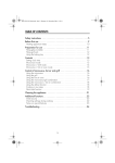
Table of Contents
Title
Introduction ....................................................................................................................
Multimeter Safety ...........................................................................................................
Getting Started Quickly ..................................................................................................
How to Use the Meter.....................................................................................................
Input Terminals and Input Alert .................................................................................
Pushbuttons...............................................................................................................
Summary of Power-On Options.................................................................................
Digital and Analog Displays.......................................................................................
Holster and Flex-Stand..............................................................................................
Applications ....................................................................................................................
Measuring Voltage (AC/DC) ......................................................................................
Measuring Current.....................................................................................................
Continuity Testing......................................................................................................
Measuring Resistance ...............................................................................................
Using Conductance for High Resistance or Leakage Tests ......................................
i
Page
1
2
3
6
6
8
13
13
17
17
19
19
20
20
21
87
Users Manual
Noisy Resistance Measurements..............................................................................
Measuring Capacitance ............................................................................................
Diode Testing............................................................................................................
Using the Analog Display..........................................................................................
Using the MIN MAX Recording Mode .......................................................................
Measuring Frequency ...............................................................................................
Measuring Duty Cycle ...............................................................................................
Pulse Width Measurements ......................................................................................
Maintenance ..................................................................................................................
General Maintenance................................................................................................
Calibration.................................................................................................................
Battery Replacement ................................................................................................
Fuse Test W.............................................................................................................
Fuse Replacement W...............................................................................................
Service W.................................................................................................................
Replaceable Parts .........................................................................................................
Specifications.................................................................................................................
ii
22
22
23
24
24
26
27
29
29
29
30
30
30
32
32
33
36
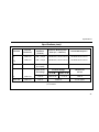
List of Tables
Table
1.
2
3.
4.
5.
6.
7.
Title
Page
International Electrical Symbols.......................................................................................... 3
Input Terminals and Limits.................................................................................................. 4
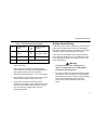
Beeper Response in Continuity Test .................................................................................. 7
Options Available at Power-on ......................................................................................... 14
Approximate Charge Rate for Capacitors......................................................................... 23
Frequency Counter Operation With Current Inputs .......................................................... 27
Replaceable Parts ............................................................................................................ 34
iii
87
Users Manual
iv
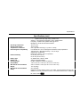
List of Figures
Figure
1.
2.
3.
4.
5.
Title
Page
Summary of Pushbutton Operation .................................................................................... 9
Holster and Flex-Stand ..................................................................................................... 18
Duty Cycle Measurement of Typical Logic Signal............................................................. 28
Battery and Fuse Replacement ........................................................................................ 31
Replaceable Parts ............................................................................................................ 35
v
87
Users Manual
vi
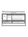
Introduction
Note
This meter has been designed and tested
according to IEC 1010-1, Safety Requirements
for Electrical Equipment for Measurements,
Control, and Laboratory Use. This manual
contains information and warnings which must be
followed to ensure safe operation and retain the
meter in safe condition. If the meter is not used
as described in this manual, the safety features
of the meter might be impaired.
Warning
Read "Multimeter Safety" before using the
meter.
The Fluke 87 True RMS Multimeter (also referred to as
"the meter") is a handheld, 4000-count instrument that is
designed for use in the field, laboratory, and at home. The
meter combines the precision of a digital meter with the
speed and versatility of a high resolution analog display.
Frequencies between 0.5 Hz and 200 kHz can be
measured with up to 0.01 Hz resolution. The meter is
powered by a 9V battery and has a rugged case sealed
against dirt, dust, and moisture. A snap-on holster, with
flexible stand (Flex-Stand), protects the meter from
rough handling. The flexible stand allows the meter to be
stood or hung.
The meter also provides:
•
A MIN MAX Recording mode, in which the meter
"remembers" the lowest and highest readings,
calculates the true average of all readings taken over
a period as long as thirty-six hours, and displays
these values. The beeper emits a Min Max Alert
when a new minimum or maximum reading is
recorded.
•
A Peak MIN MAX mode that captures changes as
short as 1 millisecond.
•
An alternate Frequency Counter mode that measures
duty cycle and displays it as a value between 0.1 and
99.9%.
•
An Input Alert that causes the beeper to sound if the
test leads are plugged into the wrong input terminals
for the function being performed.
•
A REL mode that allows you to store a reading in
memory, and display the difference between the
stored value and subsequent readings.
1
87
Users Manual
•
A Touch Hold mode that allows you to keep your
eyes fixed on the probes when taking measurements
in difficult or hazardous circumstances, then read the
display when it is convenient and safe.
•
A display back-light that makes the meter useable in
dark areas.
•
A 4 ½-digit display mode for a ten times increase in
resolution.
•
A Capacitance mode that measures capacitors from
0.01 nF to 5 µF.
After unpacking the meter, if you notice that the meter is
damaged or something is missing, contact the place of
purchase immediately. Save the shipping container and
packing material in case you have to reship the meter.
•
Avoid working alone.
•
Do not allow the meter to be used if it is damaged, or
it's safety is impaired.
•
Inspect the test leads for damaged insulation or
exposed metal. Check test lead continuity. Damaged
leads should be replaced.
•
Be sure the meter is in good operating condition.
During a continuity test, a meter reading that goes
from overload (OL) to 0 generally means the meter is
working properly.
•
Select the proper function and range for your
measurement.
•
In order to maintain the safety protection of this
meter, use only parts listed in the Service Manual.
Refer to Table 7 for the Service Manual part number.
•
CAT III: For making measurements on equipment in
fixed installations (industrial).
Multimeter Safety
Before using the meter, read the following safety
information carefully. In this manual the word, "Warning,"
is reserved for conditions and actions that pose hazard(s)
to the user; the word, "Caution," is reserved for conditions
and actions that may damage your meter. The symbols
shown in Table 1 are used internationally to denote the
electrical functions and conditions indicated. If the meter is
not used as described in this manual, the safety features
of the meter might be impaired.
2
Warning
To avoid electrical shock, use caution when
working above 60V dc or 30V ac rms. Such
voltages pose a shock hazard.
Getting Started Quickly
Table 1. International Electrical Symbols
B
F
AC-Alternating
Current
W
See Explanation in
Manual
DC-Direct
Current
T
Double insulation
(Protection Class II
C
Either DC or AC
J
Ground
I
Fuse
•
Disconnect the live test lead before disconnecting the
common test lead.
•
Follow all safety procedures for equipment being
tested. Disconnect the input power and discharge all
high-voltage capacitors through a protective
impedance before testing in the Ω and L functions.
•
When making a current measurement, turn the power
off before connecting the meter in the circuit.
•
Check meter fuses before measuring current
transformer secondary or motor winding current. (See
"Fuse Test" in the "Maintenance" Section.) An open
fuse may allow high voltage build-up, which is
potentially hazardous.
Getting Started Quickly
Examine the meter carefully, familiarizing yourself with the
layout of the input terminals, rotary switch, pushbuttons
and display. Notice the Warning information and summary
of power-on options engraved into the rear panel.
If you have used a multimeter before, simply examining
your meter will probably give you a good idea how to use
it. The following procedure is an overview of how to take
basic measurements.
Warning
To avoid electrical shock or damage to the
meter, do not apply more than 1000V between
any terminal and earth ground.
1.
Insert the test leads in the appropriate input terminals
(see Table 2). If the test leads are in the wrong input
terminals when the meter is turned on and the beeper
has not been disabled, the beeper will emit a
warning. See "Input Terminals and Input Alert",
below.
3
87
Users Manual
Table 2. Input Terminals and Limits
Function
*
**
†
4
Input Terminals
Red Lead
Black Lead
MIN Display
Reading †
K
z
COM
0.01 mV
1000V
1000V
L
z
COM
0.0001V
1000V
1000V
l
z
COM
0.01 mV
400.0 mV
1000V
e
nS
E
z
z
z
COM
COM
COM
0.01Ω
0.001 nS
0.01 nF
40.00 MΩ
40.00 nS
5.00 µF
1000V
1000V
1000V
G
z
COM
0.0001V
3.000V
1000V
A C
A
COM
0.1 mA
20.00A*
11A 1000V Fast Fuse**
mA F
µA B
mA/µA
mA/µA
COM
COM
0.001 mA
0.01 µA
400.0 mA
4000 µA
44/100A 1000V Fast Fuse**
10A continuous, 20A for 30 seconds maximum.
Fuse protected.
See the 4½ digit display mode on page 8.
MAX Display
Reading
Maximum Input
Getting Started Quickly
2.
3.
To turn the meter on and select a function, turn the
rotary switch from OFF to the appropriate switch
position. All segments on the liquid-crystal display
(LCD) will turn on for one second, then the meter is
ready for normal operation. If you would like to freeze
the display with all segments on, press and hold
down any button, while turning the meter on. As long
as the button is held down, all LCD segments will
remain on.
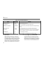
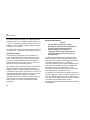
To select an additional operation, press the
appropriate pushbuttons above the rotary switch as
described in the items below. (See also, Figure 1.)
•
To operate the MIN MAX and RANGE buttons: press
to select, press again to scroll or increment, and
press and hold for two seconds to exit.
•
To operate the Hz button: press to select the
frequency mode, press again to select duty cycle, and
press again to exit.
•
To operate the back-lit display, press the YELLOW
button. The back-light automatically turns off in 68
seconds to conserve battery life.
•
To operate the remaining buttons: press to select and
press again to exit.
Note
The response of the display and the pushbuttons
slows down in the capacitance mode.
An annunciator is displayed when a mode has been
selected. A quick way to reset all the pushbuttons to their
default state is to turn the rotary switch to an adjacent
function and then back to the function you are using.
4.
To take a measurement, use the test lead probes to
make the proper contacts. Remember, insert the
meter in the circuit in parallel for voltage and in series
for current measurements. Read the measurement on
the display. If you did not manually select a range (by
using the RANGE button), the range that provides the
best resolution is automatically selected.
5.
To run a performance check of the meter, turn the
rotary switch to Ω and connect a test lead from the
T input to the mA µA input. (If you are using a
test probe, touch the half of the input contact nearest
the LCD.) The display should read 1.000 kΩ ± 5
digits. With the rotary switch still at Ω, test the A fuse
(11A) by inserting the plug end of the test lead into
the A input and test the mA uA fuse (44/100A) by
5
87
Users Manual
inserting the plug end of the test lead into the mA uA
input. The beeper emits an Input Alert if the fuses are
good.
Although this procedure will allow you to get started
quickly, we suggest that you take the time to read the
remainder of this manual so that you can learn to take full
advantage of your meter’s capabilities.
A
Input Terminals and Input Alert
Items 1-4 describe the input terminals. (See Table 1 for
overload limits.) If the test leads are connected to the
Amperes input terminal, and the function selector switch is
not in the Amp measurement position, the beeper will emit
an Input Alert. An Input Alert will also sound if the test
leads are connected to the mA uA terminal and the
function switch is not in either Amp position. After an Input
Alert sounds, the meter will attempt to take a reading from
inputs applied to the T terminal. Input Alert can be
disabled by pressing T while turning the rotary
switch from OFF to any function position.
6
Amperes Input Terminal.
For current measurements (ac or dc) up to 10A
continuous (20A for 30 seconds) when function
selector switch is set to
^
\
B
mA µA Milliamp/Microamp Input Terminal
^
\
For current measurements up to 400 mA (ac or dc)
when the function selector switch is set to
or
µAC
How to Use the Meter
This section describes your meter and how to use it. For
ease of reference, each description is numbered and
keyed to the illustration inside the front cover.
A
C
COM
Common Terminal
Return terminal for all measurements.
D
z Volts, Ohms, Diode Test Input Terminal
Function Selector Rotary Switch
E
Item 5 describes functions that are selected by setting
the rotary switch. Each time the rotary switch is
moved from OFF to a function setting, all LCD
segments will turn on for one second as part of a
selftest routine. (This selftest routine is also
performed if the rotary switch is turned slowly from
one position to another.) The meter is then ready for
normal operations and will respond to the rotary
switch and pushbuttons.
How to Use the Meter
OFF
Power to the meter is turned off.
K
Volts ac
Autoranges to the 400 mV, 4V, 40V, 400V or 1000V
range.
L
Volts dc
In Manual Ranging mode, 40 nS conductance range
(equal to a 25-100,000 MΩ range) is selectable. (See
item 9.)
Autoranges to the 05.00 nF, .0500 µF, 0.500 µF, or
05.00 µF capacitance range.
When testing continuity, the beeper sounds if the
resistance falls below the typical values indicated in
Table 3.
Autoranges to the 4V, 40V, 400V or 1000V range.
l Millivolts dc
Table 3. Beeper Response in Continuity Test
Single 400 mV range.
Input Range
ReE
400.0Ω
4.000 kΩ
40.00 kΩ
400.0 kΩ
4.000 MΩ
40.00 MΩ
Resistance (Ω), conductance (1/Ω),
capacitance or continuity R testing.
Press BLUE button to toggle between the resistance
and capacitance function. (The response of the
display and the pushbuttons slows down in the
capacitance mode.)
Autoranges to the 400Ω, 4 kΩ, 40 kΩ, 400 kΩ, 4 MΩ,
or 40 MΩ resistance range.
L
Beeper On If
< 40Ω
< 200Ω
< 2 kΩ
< 20 kΩ
< 200 kΩ
< 200 kΩ
Diode Test
Measures forward voltage of semiconductor
junction(s) at approximately 0.5 mA test current.
Single 0-3V range.
7
87
Users Manual
^
\
Milliamps or amperes
F b
Press the YELLOW button to turn on the back-light.
Back-light turns off automatically after 68 seconds to
extend battery life.
Defaults to dc. Press BLUE button to toggle between
dc and ac.
Autoranges to the 40 mA or 400 mA range when
using the mA µA input terminal, or to the 4000 mA or
10A range when using the [A] input terminal.
µA C
Power-On Option: 4½-Digit Display Mode
The meter displays the readings at 10 times the
resolution with a maximum display at 19,999 counts.
The display is updated once per second. The 4½-digit
display mode works in all functions except
capacitance, Peak MIN MAX and 100 millisecond
MIN MAX. Use manual ranging for best performance.
Microamps
Defaults to dc. Press BLUE button to toggle between
dc and ac.
Autoranges to the 400 µA or 4000 µA range when
using the mA µA input terminal.
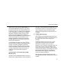
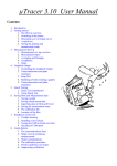
Pushbuttons
Items 6-13 describe how to use the pushbuttons. These
buttons are used (in conjunction with rotary switch) to
select operating modes and set power-on options. When a
button is pushed the beeper sounds (unless the beeper
has been turned off or the Data Output mode has been
selected). A summary of pushbutton operations is shown
in Figure 1. An annunciator is displayed to indicate that a
mode or option has been selected. A quick way to reset all
the pushbuttons to their default state is to turn the rotary
switch to an adjacent function and then back to the
function you are using.
8
Display Back-Light
G
AC or DC, Resistance or Capacitance
Press BLUE button to toggle between ac and dc
when measuring current, or between capacitance and
resistance when the rotary switch is set to ReE
How to Use the Meter
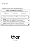
_Press to Select
_Press again to Scroll or increment
_Press and Hold Down for 2 Seconds to Exit
MIN MAX
RANGE
REL
HOLD H
Hz
PEAK MIN MAX
_Press to Select
_Press again to Exit
_Press to Select Fequency
_Press again to Select Duty Cycle
_Press again to Exit
_Press to Turn on Back Light
_Turns Off Automatically After 68 Seconds
ep1f.eps
Figure 1. Summary of Pushbutton Operation
9
87
Users Manual
Power-On Option: Disable Automatic Power-off
Automatic Power-off extends the life of the battery by
turning part of the meter off if neither the rotary switch
nor a pushbutton is operated for half an hour.
(Automatic Power-off is not allowed in the MIN MAX
Recording or Data Output modes.) The meter turns
back on if either the rotary switch is turned or a
pushbutton is pressed.
H MMinimum (MIN), Maximum (MAX),
Average (AVG) Recording
Press Mto enter the MIN MAX Recording mode
(manual range only). Select the proper range before
selecting MIN MAX to ensure that the MIN MAX
reading will not exceed the measurement range. The
minimum, maximum, and average values are then
reset to the present input; the RECORD annunciator
turns on; the AUTO annunciator turns off; and the
automatic power-off feature is disabled.
In the MIN MAX Recording mode, the minimum and
maximum readings are stored in memory. The beeper
emits a tone when a new minimum or maximum value
is recorded. A continuous beeper tone is emitted
when an overload is recorded. Push Mto cycle
10
through the maximum (MAX), minimum (MIN),
average (AVG), and present readings. The MIN,
MAX, or AVG annunciator turns on to indicate what
value is being displayed. If an overload is recorded,
the averaging function is stopped and the average
value becomes OL (overload).
The true average of all the readings taken over at
least a thirty-six hour period can be displayed. If this
duration is exceeded, the actual minimum and
maximum readings will continue to be captured and
can be displayed. However, new averages are no
longer calculated. The last average calculated is
retained as the average reading.
At normal (default) record speed, changes to the
voltage, current, or resistance inputs that last at least
100 milliseconds are recorded, and the "100 ms"
annunciator turns on. Press and hold down the
Mfor 2 seconds to exit and erase recorded
readings.
In the MIN MAX mode, press Tto select the
Peak MIN MAX mode ("1 ms", "RECORD", and
"MAX" are displayed). Voltage or current inputs that
last for 1 milliseconds or longer are captured. Press
Mto select the minimum (MIN) reading. Press
How to Use the Meter
again to return to the maximum (MAX) reading. To
reset the Peak MIN MAX mode press Ttwice:
the first press exits the mode, and the second press
re-enters the mode. To completely exit the MIN MAX
mode, press Mfor one second. In Peak MIN
MAX mode, the present reading, average (AVG)
readings, and analog display are not displayed.
Before selecting Peak MIN MAX, select DC voltage or
current to DC couple the input waveform; or AC
voltage to capacitively couple the input waveform.
Peak MIN MAX works in all functions except ohms,
frequency and capacitance.
In the MIN MAX Recording mode, press Ito
stop the recording of readings; press again to restart
recording. If recording is stopped, the minimum,
maximum, average, and present values are frozen,
but the analog display continues to be active. When
recording is stopped, the stored readings are not
erased and you can still scroll through these
readings.
Power-On Option: Select High Accuracy MIN
MAX Recording
The High Accuracy MIN MAX Recording mode has a
response time of approximately 1 second. Changes of
more than 1 second duration are recorded. The "1 s"
annunciator is turned on. In the Frequency Counter
mode, readings are always recorded at the high
accuracy recording speed; the response time is not
selectable.
I KManual Ranging
Press Kto select the Manual Range mode and
turn off the AUTO annunciator. (The meter remains in
the range it was in when manual ranging was
selected.)
In the Manual Range mode, each time you press
Kbutton, the range (and the input range
annunciator) increments, and a new value is
displayed. If you are already in the highest range, the
meter "wraps around" to the lowest range. (In the
Frequency Counter mode, pressing Kmanually
selects the input voltage or current range.) To exit the
Manual Range mode and return to autoranging,
Press and hold down Kfor 2 seconds. The
AUTO annunciator turns back on.
When the range is changed manually, the Touch
Hold, MIN MAX Recording, and REL[ative] modes are
disabled.
11
87
Users Manual
Power-On Option: Rotary Switch Test
The Rotary Switch Test is used only for servicing
purposes. See the 80 Series Service Manual for
details. In the Rotary Switch Test mode, normal meter
functions are disabled. To exit the Rotary Switch
mode, turn the rotary switch to OFF and back to any
switch setting.
J I
Display Hold
Warning
Touch hold will not capture unstable or noisy
readings. Do not use touch hold to determine
that circuits with dangerous voltage are dead.
Press Ito toggle in and out of the Touch Hold
mode, except if you are already in the MIN MAX
Recording or Frequency Counter mode.
In the Touch Hold mode, the H annunciator is
displayed and the last reading is held on the display.
When a new, stable reading is detected, the beeper
emits a tone, and the display is automatically
updated. Pressing Mwhen you are in the Touch
Hold mode causes you to exit Touch Hold and enter
the MIN MAX Recording mode.
12
In the MIN MAX Recording mode, press Ito
stop the recording of readings; press Iagain to
resume recording. (Previously recorded readings are
not erased.)
In the Frequency Counter mode (Hz), press Ito
stop the display; press Iagain to start it.
K T
Continuity Beeper/Peak MIN MAX
Press Tto toggle the beeper on or off for
continuity testing in the ohms function.
The beeper responds as indicated in Table 2.
In the Frequency Counter mode, press Tto
change the trigger slope from positive-going edges to
negative-going edges. The slope selected is indicated
by the analog display polarity annunciator (±).
In the MIN MAX mode, press Tto toggle in and
out of the Peak MIN MAX mode. See item 8.
Power-On Option: Disable Beeper
When the beeper has been disabled, all beeper
functions are turned off. The beeper is automatically
disabled if the meter is in the Data Output mode.
How to Use the Meter
L C
Relative Readings
Press Cto enter the Relative mode, zero the
display, and store the displayed reading as a
reference value. The relative mode annunciator (∆) is
displayed. Press Cagain to exit the relative
mode.
In the Relative mode, the value shown on the LCD is
always the difference between the stored reference
value and the present reading. For example, if the
reference value is 15.00V and the present reading is
14.10V, the display will indicate -0.90V. If the new
reading is the same as the reference value, the
display will be zero.
M F
Frequency Counter Mode and Duty
Cycle
Press the Fto select the Frequency Counter
mode; press again to select duty cycle (the alternate
counter function); press again to exit. The analog
display does not operate in either the Frequency
Counter mode or duty cycle.
In Frequency Counter mode, the Hz annunciator is
displayed. The frequency function autoranges over
five ranges: 199.99 Hz, 1999.9 Hz, 19.999 kHz,
199.99 kHz, and greater than 200 kHz. The RANGE
button manually selects the voltage or current input
range. If duty cycle is selected, readings from 0.1
through 99.9 are displayed. The "Hz" annunciator
turns off and "%" turns on.
Power-On Option: High Input Impedance Mode
The input impedance of the l function (400 mV
range) is changed from 10 megohms to greater than
4000 megohms.
Summary of Power-On Options
You can select a number of options each time you turn the
meter on. These power-on options (also listed on the rear
of the meter) are selected b holding down one or more of
the pushbuttons for approximately 2 second while turning
the function switch to any ON position. All power-on option
are only disabled when the rotary switch is turned to OFF.
Each power-o option is discussed in detail under
"Pushbuttons" and summarized in Table 4.
Digital and Analog Displays
Items 14-19 describe the digital and analog displays and
LCD annunciators.
13
87
Users Manual
Table 4. Options Available at Power-on
Option
Pushbutton
Function
Automatic Power-off
Blue
Disable Automatic Power-off
4½ Digit Mode
Yellow
Select 4½ digit display. Full scale 19,999 counts.
MIN MAX Record Speed
MIN MAX
Select High Accuracy record speed. (Response time approximately 1
second)
Rotary Switch Test
Range
For servicing purposes only. See 80 Series Service Manual
Data Output
Hold H
Enable ultrasonic data transmission. (For use in factory testing only,
cannot be modified for customer use. Beeper functions disabled.)
Disable Beeper
R
Turns off all beeper functions
High Input Impedance in mV DC
Hz
Provides >4000 MΩ input impedance for 400 mV dc range
N
Digital Display
Digital readings are displayed on a 4000-count
display with polarity (±) indication and automatic
decimal point placement. When the meter is turned
on, all display segments and annunciators appear
briefly during a selftest. The display updates four
times per second, except when frequency readings
are taken. Then the update rate is 3 per second.
14
O
Analog Display
The analog display is a 32-segment pointer that
updates at a 40 times per second rate and is the
best display to use for readings that are changing. It
does not operate in the Capacitance or Frequency
Counter functions or in the Peak MIN MAX mode.
How to Use the Meter
For increased sensitivity, the analog pointer moves
across the scale four times for each range. The
pointer returns to 0 (wraps around) when the
equivalent digital display reaches 1024, 2048, and
3072 counts. Select the next higher range if the
pointer is too sensitive.
R
Displays 4, 40, 400, or 4,000 input range for volts,
amps, or ohms, and 400 mV.
S
The analog pointer indicates a value lower than the
digital display (up to 2.5% of range). Examples on
the 40V range are:
Digital Display =
Analog Pointer=
Wrap
=
Indication =
5.00V
4.8
First
4.8V
15.00V
4.5
Second
14.5V
25.00V
4.5
Third
24.5V
35.00V
4.2
Fourth
34.2V
With stable inputs, use the digital display for the best
sensitivity and precision.
P
0
1
2
3
4
5
6
7
8
9
0
Analog Display Scale
Scale for each 1000 counts in the digital display.
Q
± Analog Display Polarity
Indicates the polarity of the input except in the
Frequency Counter mode, when it indicates the
polarity of the trigger slope (edge).
4000 Input Range Annunciator
mV
OL
Overload Indication
Displayed on digital display when input (or math
calculation in REL mode) is too large to display. If you
are taking duty cycle readings, OL is displayed if the
input signal stays high or low. All segments are
illuminated on analog display.
Items 20-23 describe annunciators that indicate the mode
or state in which the meter is operating:
T
AUTO
Autorange
Meter is in the autorange mode and will automatically
select the range with the best resolution. Meter
powers-on in autorange mode.
In the autorange mode, the meter ranges up at 4096
counts and ranges down at 360. When the meter is in
the Manual Range mode, the overrange arrow is
displayed until you manually select a range
appropriate for the input value.
See item 9 for manual ranging.
15
87
Users Manual
UU
Input changes of 100 milliseconds or longer will be
recorded. In the 1 s High Accuracy MIN MAX
Recording Mode, the recording speed is 1 second.
Low Battery
Meter is powered by a single 9V battery, with a typical
life of 400 hours with an alkaline battery. At least 8
hours of battery life remain when U is first displayed.
A battery check is taken between measurements.
V
R
Beeper
Continuity test is enabled. See item 11 and Table 2.
Items 24 through 31 describe math function annunciators
and the annunciators that indicate the units of the value
displayed.
X ∆
Relative Mode
The value displayed is the difference between the
present measurement and the previously stored
reading. See item 12.
Y
16
100 ms Normal Recording Speed in MIN MAX
Recording Mode
Peak MIN MAX Recording Mode
Input changes of 1 millisecond or longer will be
recorded.
Negative Polarity
Automatically indicates negative inputs. When REL is
enabled, indicates negative results of math
calculations.
W
1 ms
Z
RECORD
Minimum, Maximum, and Average
Recording
Readings are being recorded in the MIN MAX
Recording mode. A maximum (MAX), minimum
(MIN), or average (AVG) reading can be displayed.
27 MAX
Maximum Value in MIN MAX Recording
Mode
The value displayed is the maximum reading taken
since the MIN MAX Recording mode was entered.
Applications
28 MIN
Minimum Value in MIN MAX Recording
Mode
The value displayed is the minimum reading taken
since the MIN MAX Recording mode was entered.
29 AVG
Average Value in MIN MAX Recording
Mode
The value displayed is the true average of all
readings taken since the MIN MAX Recording mode
was entered.
30 H
Hold
The meter is operating in a Display Hold mode. See
item 10 for Display Holds.
31 The following annunciators indicate the unit of the
value displayed:
AC
DC
V
mV
A
mA
uA
Alternating current or voltage
Direct current or voltage
Volts
-3
Millivolts (1 x 10 volts)
Ampere (amps). Current
-3
Milliampere (1 x 10 amps)
-6
Microampere (1 x 10 amps)
-9
Nanosiemens (1 x 10 siemens). Conductance
(1/Ω)
%
Percent Annunciator (for duty cycle readings
only)
Ω
Ohms. Resistance
3
kΩ Kilohm (1 x 10 ohms). Resistance
6
MΩ Megohm (1 x 10 ohms). Resistance
Hz Hertz (1 cycle/sec). Frequency
3
kHz Kilohertz (1 x 10 cycles/sec). Frequency
-6
µF Microfarads (1 x 10 Farads). Capacitance
-9
nF Nanofarads (1 x 10 Farads). Capacitance
nS
32
Duty
Not Used
Not Used
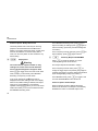
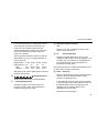
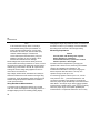
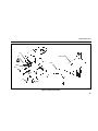
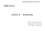
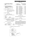
Holster and Flex-Stand
The meter comes with a snap-on holster that absorbs
shocks and protects the meter from rough handling. The
holster is equipped with a Flex-Stand. Some uses of the
holster with Flex-Stand are shown in Figure 2.
Applications
This section discusses some common applications for
your meter, and alerts you to some considerations to keep
in mind when taking measurements.
17
87
Users Manual
Holster With Flex-stand Bent
Holster With Probe In Clip
Holster With
Flex-stand Extended
POWER-UP OPTIONS
PRESS 2 SEC. WHILE TURNING METER ON
LOW, OHMS/HIGH RESOLUTION
ZERO
DISABLE AUTOMATIC POWER-OFF
MIN MAX
HI ACCURACY, 1 SEC. RESPONSE
RANGE
AUTORANGE VDC, VAC
HOLD
HI IMPENDANCE mV DC INPUT
ALERT
TURN OFF BEEPER
TEST ROTARY SWITCH
RPM
WARNING
TO AVOID ELECTRICAL SHOCK REMOVE
TEST LEADS BEFORE OPENING CASE
TO PREVENT DAMAGE OF INJURY
INSTALL QUICK ACTING FUSES WITH
AMP/VOLT RATINGS SHOWN.
F 1A 600V
MIN INTERRUPT RATING 10 000A
F 15A 600V
MIN INTERRUPT RATING 10 000A
_
+
9V NEDA 1604 6F 22 006P
JOHN FLUKE MFG. CO., INC.
EVERETT, WA MADE IN U.S.A.
PATENTS PENDING
FLUKE AND PHILLIPS
THE T & M ALLIANCE
Holster With Flex-stand
Looped Over Car Door
Meter In Holster Face Down
For Protection
(Store Quick Reference Card Under Meter)
Holster With Flex-stand
Looped Over Belt
ep2f.eps
Figure 2. Holster and Flex-Stand
18
Applications
Measuring Voltage (AC/DC)
To measure voltage, connect the meter in parallel with the
load or circuit under test. Each of the five ac/dc voltage
ranges presents an input impedance of approximately 10
MΩ in parallel with less than 100 pF. Ac voltage is accoupled to the 10 MΩ input.
To improve the accuracy of dc voltage measurements
made in the presence of ac voltages, measure the ac
voltage first. Note the ac voltage range and manually
select a dc voltage range that is the same or higher than
the ac voltage range. This method improves the dc
voltage accuracy by ensuring that the input protection
circuits are not being activated. A typical application is
measuring the dc offset voltage of an amplifier in the
presence of an ac signal.
Measurement errors due to circuit loading can result when
making either ac or dc voltage measurements on circuits
with high source impedance. In most cases, the error is
negligible (0.1% or less) if the measurement circuit source
impedance is 10 kilohms or less.
Measuring Current
Warning
Do not attempt an in-circuit current
measurement where the potential to earth is
greater than 1000V. You may damage the
meter or be injured if the fuse blows while
current is being measured in a circuit which
exhibits an open circuit voltage greater than
1000V.
To measure current, connect the meter in series with the
load or circuit under test. Press the BLUE button to toggle
between alternating and direct current.
If you do not know approximately what the current is,
connect the circuit to the A input terminal first to see if you
have a safe level for the mA µA input terminal. Use the
mA µA input terminal for current up to 400 mA.
When measuring current, the meter’s internal shunt
resistors develop a voltage across the meter’s terminals
called "burden voltage." This voltage drop is very low in
your meter, but it may affect precision circuits or
measurements.
19
87
Users Manual
To calculate the burden voltage: in A, multiply the display
reading by 0.03V; in mA, multiply the display reading by
1.8 mV; in µA, multiply the display reading by 100 µV. For
example, at a 20 mA display reading, the burden voltage
is 20.00 x 1.8 mV = 36 mV.
The approximate resistance between the input terminals is
0.03 ohms for A, 1.8 ohms for mA, and 100 ohms for µA.
Continuity Testing
Continuity testing verifies that circuit connections are
intact. To perform audible continuity tests, set the rotary
switch to ReE press T and connect the meter to
your circuit. Test resistances below the values listed in
Table 3 cause the meter to emit a continuous tone. Use
the 400 ohm range for most wiring checks.
The continuity mode is extremely fast and can be used to
detect either shorts or opens that last for as little as 1
millisecond. When a change is detected, the beeper tone
is "stretched" to last at least 1/4 second so you can hear it
and detect both shorts and opens. This can be a valuable
troubleshooting aid when looking for intermittents
associated with cables, connections, switches, relays, etc.
If the test value is very close to the threshold, erratic
beeps can also occur due to environmental electrical
noise (EMI).
20
Measuring Resistance
Caution
Turn off power on the test circuit and
discharge all capacitors before attempting incircuit resistance measurements. If an
external voltage is present across a
component, it will be impossible to take an
accurate measurement of the resistance of
that component.
The meter measures resistance by passing the same
current through a precision reference resistor and the
external circuit or component, then ratios and measures
the voltage drop across each (Ω = Vunknown/
Vreference). Remember, the resistance displayed by the
meter is the total resistance through all possible paths
between the probes. This explains why in-circuit
measurement of resistors does not often yield the ohms
value indicated by the resistor’s color code.
The resistance in the test leads can diminish accuracy on
the lowest (400-ohm) range. The error is usually 0.1 to 0.2
ohms for a standard pair of test leads. To determine the
error, short the test leads together and read the resistance
of the leads. Use the Relative (REL) mode to
automatically subtract the lead resistance from resistance
measurements.
Applications
When measuring resistance, be sure that the contact
between the probes and the circuit under test is good.
Dirt, oil, solder flux, or other foreign matter seriously
affects resistance.
Most in-circuit resistance measurements can be made
without removing diodes and transistors from the circuit.
The full-scale measurement voltage produced on ranges
below 40 MΩ does not forward-bias silicon diodes or
transistor junctions enough to cause them to conduct. Use
the highest range you can (except 40 MΩ) to minimize the
possibility of turning on diodes or transistor junctions. Fullscale measurement voltage in the 40-MΩ range does
forward-bias a diode or transistor enough to cause it to
conduct.
In resistance (and all other functions except current), the
mA µA input is connected to a 1-kΩ resistor. If the mA µA
input protection fuse is good, this input can be used as a
partial check of proper operation in resistance. The input
receptacles have split contacts; touch the probe to the half
nearest the LCD. The 1-kΩ resistor is protected by a 3diode clamp. Do not apply external voltage; it may blow
the fuse.
Using Conductance for High Resistance or
Leakage Tests
Conductance is the inverse of resistance (i.e., 1/ohms)
-9
and is measured in units of nanosiemens (nS = 1 x 10
Siemens). The 40-nS range on your meter effectively
extends the resistance measurement capability to 100,000
MΩ. The 40-nS range can, therefore, be used to test the
resistance or leakage in insulators, diodes, transistors,
cables, connectors, printed circuit boards, transformers,
motors, capacitors, or other high resistance components.
K
To measure conductance, set the rotary switch to MJ
and press Kto manually increment to the 40-nS
range. Plug the test leads into the VJL and COM input
terminals, and then connect these leads across the unit
under test. The reading displayed is in units of
conductance (nS). To convert this reading to megohms,
divide the reading into 1000 (1000/displayed reading in nS
= MΩ). For example 2.00 nS converts to 500 MΩ
(1000/2.00). High value resistance measurements are
susceptible to induced noise and may require careful
shielding. To smooth out most noisy readings, enter the
MIN MAX Recording mode and scroll to the average
(AVG) reading.
21
87
Users Manual
Note
In the conductance range, there is normally a
small residual reading with open test leads. To
ensure accurate measurements, connect clean
test leads to the meter and (with the leads open)
read the residual leakage in nanosiemens.
Correct subsequent measurements by using the
Relative mode (REL) to zero the display, which
subtracts the residual from the readings.
Diode leakage tests require that the diode junction be
reverse-biased when being measured. To do this, connect
the anode of the diode to the COM input terminal and the
cathode (ring) of the diode to the VJL input terminal.
Leakage at the test voltage being applied can then be
read in terms of conductance.
High-voltage, stacked diode, assemblies can usually be
tested for forward and reverse resistance changes using
conductance. These assemblies typically have such high
forward voltage drops that the diode test or resistance
modes cannot test them.
Noisy Resistance Measurements
Your Fluke meter is designed to tolerate up to several
volts of ac noise. Noise appears as changing numbers on
the digital display and as an oscillating analog display.
22
Changing the range may reduce the noise. To smooth out
the effect of noise on your readings, enter the MIN MAX
Recording mode and scroll to the average reading.
Measuring Capacitance
Caution
Turn off power and discharge the capacitor
before attempting a capacitance
measurement. Use the (F) function to confirm
that the capacitor is discharged.
The meter measures capacitance by charging the
capacitor with a known current, measuring the resultant
voltage, and calculating the capacitance. The
measurement takes about 1 second per range (push
button responses also take about 1 second). The
capacitor charge can be up to 1.2V.
K
For measuring capacitor values up to 5.0 µF, turn the
, press the BLUE button, and
rotary switch to MJ
connect the test leads to the capacitor. The meter will
select the proper range automatically. Each measurement
takes about 1 second per range. When making repeated
measurements of similar values, press Kto manually
select the proper range and to speed up subsequent
measurements. For capacitors less than 5 nF or in noisy
Applications
environments, use short test leads or a test fixture (1 nF =
1000 pF).
The measurement accuracy of capacitors less than 5 nF
can be improved by first using the Relative mode to zero
the display and automatically subtract the residual meter
and test lead capacitance. Since the Relative mode also
selects manual ranging, zero the residual capacitance
only when measuring small value capacitors.
Residual voltage charges on the capacitor, or capacitors
with poor insulation resistance or poor dielectric
absorption may cause measurement errors.
To check capacitors larger than 5 µF, select Ω with the
rotary switch (or press the BLUE button if you are in the
capacitance mode). Select an appropriate range from
Table 5. Discharge the capacitor, connect the capacitor to
the meter, and time the number of seconds it takes for the
charge to go from zero to full scale. At full scale, all of the
analog display segments are on. To estimate the value of
the capacitor, multiply the number of seconds times the
charge rate (µF/sec) in Table 5. For example, a 10 µF
capacitor takes about 34 seconds to charge in the 4 MΩ
range or 3.4 seconds in the 400 kΩ range. To reconfirm
your estimate, reverse the test leads; when the capacitor
discharges to zero (the analog display polarity switches
from - to +), start timing the recharge to full scale.
Diode Testing
To perform a diode or transistor junction test: plug the test
leads into the VJL and COM inputs, turn the rotary
switch to L and connect the test leads across the
diode(s).
In diode test, voltage is developed across the
component(s) by a test current (approximately 0.6 mA with
the test leads shorted) from the meter. Voltage is read on
a single 0 to +3.000V range that can measure up to five
silicon diode or transistor junctions in series. For a silicon
diode, the typical forward voltage should be about 0.6V.
Voltages greater than 3.00V or open test leads produce
an overload (OL) reading. If the digital reading is the same
in both directions, the diode junction is probably shorted. If
the display reads OL in both directions, the diode junction
is probably open. To protect sensitive devices, the open
test lead voltage from the meter will not exceed 3.9V.
Negative inputs (from an external power source, for
example) are not suppressed.
Table 5. Approximate Charge Rate for Capacitors
Range
400Ω
4 kΩ
40 kΩ
400 kΩ
4 MΩ
µF/sec
2600
275
29
2.9
0.29
23
87
Users Manual
Use the Touch Hold mode (see item 10) to make audible
diode tests. When the test leads are placed across the
diode, a good diode or transistor junction will cause the
meter to beep (and update the display) in the forwardbiased direction and remain silent in the reverse-biased
direction. A short or resistance below about 30 kΩ will
cause a beep in both directions. If an open is detected,
the meter will remain silent in both directions.
Using the Analog Display
The analog display is easy to use and interpret. It
functions much the same as the needle on an analog
meter without the mechanical overshoot inherent in
needle movements.
The analog display is especially useful for peaking and
nulling, and observing rapidly changing inputs. The analog
display response time is fast, and it can be used to make
approximate adjustments quickly. The 4000-count digital
display can then be used for final adjustment.
The analog display can also be used for limited diagnostic
purposes. In situations where rapidly fluctuating signal
levels make the digital display useless, the analog display
is ideal. Like the needle on a Volt-ohm-milliammeter
(VOM), the analog display excels at displaying trends, or
slowly changing signals. Many diagnostic routines using
24
the analog display require practice. You will usually be
looking for good or bad signal patterns that occur over
some span of time. Noisy resistance measurements, for
instance, create such patterns. Therefore, familiarity with
analog display response and movement is necessary to
accurately interpret a signal pattern. Compare the analog
display response when making measurements on a unit
known to be good, to the analog display response when
making measurements on a faulty unit.
Using the MIN MAX Recording Mode
The MIN MAX Recording mode can be used to catch
intermittents and turn on or turn off surges, verify
performance, measure while you are away ("baby sit"), or
take readings while you are operating the equipment
under test and cannot watch the meter. The audible Min
Max Alert indicates when a new minimum or maximum
value has been recorded.
You can select either a 100 millisecond, 1 millisecond
(Peak), or 1 second (high accuracy) "response time" for
recording minimum and maximum readings. The response
time is the length of time an input must stay at a new
value to record the full change.
The 100 millisecond response time is best for recording
power supply surges, inrush currents, and finding
Applications
intermittent failures. This mode follows the update time of
the analog display. (The minimum and maximum
excursions of the analog display get recorded.)
the meter). When you display the average, the reading
rate slows somewhat in order to calculate the average of
the accumulated readings.
The 1 millisecond Peak MIN MAX mode is ideal for
recording transients, especially from intermittent power
lines or connections. This mode can also be used to
measure the + and - peak values of sinewaves up to
about 450 Hz, for easy measurement of both peak line
voltage and line current measurements of power supplies
and electrical equipment.
The average reading is useful for smoothing out unstable
or changing inputs, calculating power consumption (such
as kilowatt hours), estimating the percent of time a circuit
is operational, or verifying circuit performance (or
temperature with the optional 80TK Thermocouple
Module).
The high accuracy mode (1 second response time) follows
the digital display and can be selected as a power-on
option by pressing Mwhile turning the meter on. This
mode has the full accuracy of the meter and is best for
recording power supply drift, line (mains) voltage changes,
or circuit performance while line voltage, temperature,
load, or some other parameter is being changed.
Frequency Counter readings are recorded only in the high
accuracy mode
In the MIN MAX Recording mode, the true average of all
readings taken since entering MIN MAX is calculated. The
average value displayed in both the 100 millisecond and 1
second modes is the mathematical integral of the input
(within the response time and accuracy specifications of
If you want to record readings only during the duration of
a particular test (such as during the frequency response
sweep of an audio amplifier, for example), apply the input
signal, start the test (or sweep, in this example), and let
the meter stabilize. Now press M, then press
Iand stop the test. The minimum, maximum, and
average of all readings taken during the test are now held
in memory. Momentarily press Mto scroll to the
reading of interest. Be careful: if you hold down the
Mfor longer than a second, you will exit the MIN
MAX Recording mode and erase the memory. As long as
the rotary switch is not turned and the other pushbuttons
(except REL) are not pressed, these readings will remain
in memory until the battery dies.
25
87
Users Manual
Measuring Frequency
In the Frequency Counter mode, the frequency display
autoranges to one of five ranges: 199.99 Hz, 1999.9 Hz,
19.999 kHz, 199.99 kHz, and greater that 200 kHz. For
frequencies below 10 Hz, the update rate slows and
follows the input signal. For frequencies between 0.5 Hz
and 0.3 Hz, the display may not be stable. For frequencies
below 0.3 Hz, the display shows 00.00 Hz.
For most frequency measurements, turn the rotary switch
to K, connect the meter to the signal being measured, and
then press FConnecting the meter to the signal
before pressing Hz will normally allow the meter to
autorange to an appropriate range, but the minimum input
signal required to trigger the frequency counter varies,
depending on the range and frequency (see
Specifications). If the input signal is below the trigger
level, frequency measurements will not be taken. If your
readings are unstable, the input signal may be near the
trigger level for that range. You can usually correct this by
selecting a lower range. In the Frequency Counter mode,
the range (displayed in the lower-right corner of the LCD)
will only change when you press the Kbutton.
If your readings seem to be a multiple of what you
expected, your input signal may have distortion or ringing.
26
(For example, electronic motor controls distort both
voltage and current waveforms.) Select a higher input
range if you suspect multiple triggering. An alternative is
to turn the rotary switch to F or l, which will shift the
trigger level from 0V to a positive voltage that changes
with each range. In general, the lowest frequency
displayed is the correct one.
In the Frequency Counter mode, the input range acts like
an attenuator, the G function ac-couples the input signal,
and the F and l functions dc-couple the input signal.
The F function is optimized for triggering on logic and
switching signals. The 4V dc range is optimized to trigger
on all common 5V logic families (triggers at 1.7V ± 0.1V).
High frequency logic signals may require the use of the
400 mV ac range. The 40V dc range is optimized to
trigger on automotive switching signals (triggers at 4V ±
1V). All ranges in the F function trigger at approximately
10% of range, except for the 4V range.
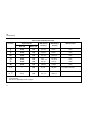
Frequency measurements can be made on current inputs.
The inputs are always dc-coupled. The triggering
characteristics are shown in Table 6.
Applications
Table 6. Frequency Counter Operation With Current
Inputs
Approximate Trigger
Level
Input
Range
Approximate
Sensitivity
(0.5 Hz - 20 kHz)
AC Current
DC Current
µA
mA
A
300 µA
30 mA
3A
0 µA
0 mA
0A
400 µA
40 mA
4A
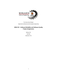
Measuring Duty Cycle
Duty Cycle (or duty factor) is an alternate Frequency
Counter mode that displays, in percent, the time the input
signal is above the trigger level (or below the trigger level
if the negative trigger slope is selected). The Duty Cycle
mode is optimized for measuring the on or off time of logic
or switching controls. Many industrial control systems
(electronic fuel injection in automobiles, for example) are
pulse-width modulated, and duty cycle measurements
provide a quick check on their performance.
For logic level signals, use the 4V dc range. For 12V
switching signals in automobiles, use the 40V dc range.
For sine waves, use the most sensitive range you can
without getting double triggering. (Normally, a clean signal
can be up to ten times the amplitude of the range you are
on.) Duty cycle measurements can also be used as an
indication of potential triggering problems on sine wave or
near sine wave signals. If you do not measure
approximately 50% duty cycle, you may have a distorted
waveform.
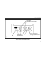
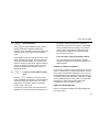
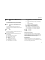
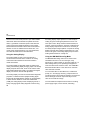
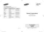
In Duty Cycle (and Frequency Counter) mode, the slope
(or edge) on which the counter triggers is selected by
pressing T. The slope selected is indicated by a + or
- annunciator in the lower-left corner of the LCD. The
waveform shown in Figure 3 represents the duty cycle
measurement of a typical logic signal.
The manner in which your meter takes duty cycle
measurements allows it to be very tolerant of aperiodic
(repetitive but not periodic) signals. Duty cycle
measurements on low frequency (<400 kHz) aperiodic
logic signals, especially serial communication signals, is a
simple form of signature analysis. A known pattern will
read the same duty cycle every time (if the pattern repeats
in less than 1/3 second).
27
87
Users Manual
+Slope
Trigger Point
-Slope
Trigger Point
30% +Slope
70% -Slope
100%
ep3f.eps
Figure 3. Duty Cycle Measurement of Typical Logic Signal
The precision and resolution of the duty cycle
measurements are achieved by averaging many
repetitions of the input signal. In rare cases, this
averaging technique (which is similar to pulse-width
averaging in a conventional counter) may cause a
measurement problem called "aliasing." Aliasing results
when the frequency of the input signal happens to be
exactly synchronized with the reference crystal oscillator
of the meter. This occurs when the frequency of the input
signal can be exactly divided into the frequency of the
oscillator (131,072 Hz) or one of the oscillator’s
harmonics. When they are nearly synchronized, the
meter is "blind" to the correct duty cycle, and the display
28
will alternate between incorrect readings. If this occurs,
and the frequency reading was stable, press Mto
select the MIN MAX Record mode and scroll to the
average display. The average display will stabilize on the
correct duty cycle.
A common duty cycle measurement is the "dwell" angle
in an automobile. Dwell is the number of degrees of
distributor rotation that the points remain closed (or
current is flowing in the coil). Use the following to convert
a dwell angle to duty cycle (in percent):
Maintenance
% Duty Cycle =
Dwell (degrees) x No. of Cylinders x 100
360 degrees
Maintenance
To make a dwell measurement, set the rotary switch to F,
select the 40V range, press Ftwice (the %
annunciator on the right side of the LCD should turn on),
and press the T(to select the negative trigger slope
so the measurement will be the "off" or points closed
time). Then connect the COM input to ground, and
connect the VJL input to the low (or switched) side of
the coil. Most automobiles have the points closed for a
duty cycle between 50-70%.
Repairs or servicing not covered in this manual should
only be performed by qualified personnel as described in
the 80 Series Service Manual (refer to Table 7 for part
number).
Pulse Width Measurements
1.
Turn the multimeter off and remove all test leads.
For a periodic waveform (that is, repetitive at equal time
intervals), a duty cycle measurement can be easily
converted to pulse width. First measure the frequency and
then measure the duty cycle. Toggle T to select the
polarity of the pulse you want to measure. To convert
frequency and duty cycle measurements into a pulse
width, use the following:
2.
Shake out the input receptacles.
3.
Use a clean swab in each of the four terminals to
dislodge and clean out the contamination.
4.
Soak a new swab with the cleaning and oiling agent
WD40. Work this swab around in the A and mA µA
terminals. Since the oiling agent insulates the
terminals from moisture-related shorting, this
preventive treatment ensures against future
erroneous Input Alerts.
Pulse Width =
% Duty Cycle / 100
Frequency
General Maintenance
Periodically wipe the case with a damp cloth and
detergent (do not use abrasives or solvents). If the input
alert is falsely activated by moisture:
29
87
Users Manual
Using a Phillips-head screwdriver, remove the three
screws from the case bottom and turn the case over.
Calibration
Calibrate your meter once a year to ensure that it
performs according to its specifications. Contact the
nearest Service Center or refer to the 80 Series Service
Manual for calibration procedures. For replacement parts,
see the parts list at the end of this manual.
3.
Lift the input terminal end of the case top until it
gently unsnaps from the case bottom at the end
nearest the LCD.
4.
Lift the battery from the case bottom, and carefully
disconnect the battery connector leads.
5.
Snap the battery connector leads to the terminals of a
new battery and reinsert the battery into the case
bottom. Dress the battery leads so that they will not
be pinched between the case bottom and case top.
6.
Ensure that the case top rotary switch and circuit
board switch are in the OFF position.
7.
Replace the case top, ensuring that the gasket is
properly seated and the two snaps on the case top (at
the end near the LCD) are engaged. Reinstall the
three screws.
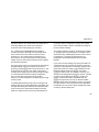
Warning
To avoid electrical shock, remove the test
leads and any input signals before replacing
the battery or fuses. To prevent damage or
injury, install only quick acting fuses with the
amp/volt ratings shown in Figure 4.
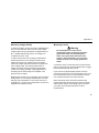
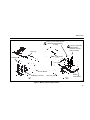
Battery Replacement
The meter is powered by a single 9V battery (NEDA 1604,
6F22, or 006P). Referring to Figure 4, use the following
procedure to replace the battery:
1.
2.
30
Disconnect test leads from any live source, turn the
rotary switch to OFF, and remove the test leads from
the front terminals.
The case bottom is secured to the case top by three
screws and two internal snaps (at the LCD end).
Fuse Test
Use the following procedure to test the internal fuses of
the meter.
Maintenance
Fuse (F2) F11A, 1000 VAC/DC
Minimum Interrupt Rating
17 000A
Fuse (F1) F44/100A,
1000 VAC/DC
Minimum Interrupt
Rating 10 000A
Case Top
Snaps
9V Battery
LCD
Case Bottom
Battery
Battery Connector
Case Top
"A"
Case Bottom
"B"
ep4f.eps
Figure 4. Battery and Fuse Replacement
31
87
Users Manual
K
1.
Turn the rotary selector switch to MJ
2.
Plug a test lead into the VJL input terminal and
touch the probe to the [A] input terminal. Because the
receptacles of the input terminals contain split
contacts, be sure that you touch the probe to the half
of the receptacle contact that is nearest the LCD.
3.
.
The display should indicate between 00.0 and 00.5
ohms. This tests F2 (11A, 1000V). If the display
reads OL (overload), replace the fuse and test again.
If the display reads any other value, have the meter
serviced.
4.
Move the probe from the A input terminal to the mA
µA input terminal.
5.
The display should indicate between 0.995 kΩ and
1.005 kΩ. This tests F1 (44/100A, 1000V). If the
display reads OL (overload), replace the fuse and test
again. If the display reads any other value, have the
meter serviced.
Fuse Replacement
Referring to Figure 4, use the following procedure to
examine or replace the meter’s fuses:
32
1.
Perform steps 1 through 3 of the battery replacement
procedure.
2.
Remove the defective fuse by gently prying one end
of the fuse loose and sliding the fuse out of the fuse
bracket.
3.
Install a new fuse of the same size and rating. Make
sure the new fuse is centered in the fuse holder.
4.
Ensure that the case top rotary switch and circuit
board switch are in the OFF position.
5.
Replace the case top, ensuring that the gasket is
properly seated, the battery leads are properly
dressed, and the two snaps on the case top (at the
end near the LCD) are engaged. Reinstall the three
screws.
Service
If the meter fails, check the battery and fuse(s) and
replace as needed. If the meter still does not work
properly, review this manual to make sure you are
operating it correctly. If the meter still malfunctions, pack it
securely in its original shipping container and forward it,
postage paid, to the nearest Service Center. Include a
description of the malfunction. Fluke assumes NO
responsibility for damage in transit.
Replaceable Parts
A meter under warranty will be promptly repaired or
replaced (at Fluke’s option) and returned at no charge.
See the registration card for warranty terms. If the
warranty has lapsed, the meter will be repaired and
returned for a fixed fee.
To locate an authorized service center, call Fluke using
any of the phone numbers listed below, or visit us on the
World Wide Web: www.fluke.com
1-800-443-5853 in U.S.A and Canada
Replaceable Parts
Note
When servicing the meter, use only the
replacement parts specified.
Replaceable parts are shown in Figure 5 and listed in
Table 7. To order replacement parts in the USA, call 1800-526-4731. To order outside the USA, contact the
nearest Service Center.
31 40 267 8200 in Europe
206-356-5500 from other countries
33
87
Users Manual
Table 7. Replaceable Parts
Item
BT1
F1 P
F2 P
H1
MP1
MP2
TM1
TM2
TM3
Description
Fluke Part Number
Quantity
Battery, 9V
614487
1
Fuse, F44/100A, 1000 VAC/DC
943121
1
Fuse, F11A, 1000 VAC/DC
943118
1
Screw, Case
832246
3
Foot, Non-Skid
824466
2
O-Ring, Input Receptacle
831933
1
Users Manual, Fluke 87 (English)
834192
1
Users Manual, Fluke 87 (International)
834200
Service Manual, CAT III labeled meters
617826
all other meters
834168
TM4
Quick Reference Guide, Fluke 80 Series
844290
1
TL20**
Industrial Test Lead Set (Optional)
TL75**
Test Lead Set
1
C81Y**
Holster, Yellow
1
C81G**
Holster, Gray (Optional)
C25**
Carrying Case, Soft (Optional)
P To ensure safety, use exact replacement only.
** Items marked with two asterisks are Fluke accessories and are available from you authorized Fluke distributor.
34
Replaceable Parts
F2
C81Y,C81G
F1
TL75
MP2
BT1
H1
MP1
ep5f.eps
Figure 5. Replaceable Parts
35
87
Users Manual
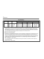
Specifications
Function
B
V†
Range
400.0 mV
4.000V
40.00V
400.0V
1000v
Resolution
0.1 mV
0.001V
0.01V
0.1V
1V
Accuracy*
50 Hz - 60 Hz
±(0.7% + 4)
±(0.7% + 2)
±(0.7% + 2)
±(0.7% + 2)
±(0.7% + 2)
45 Hz - 1 kHz
±(1.0% + 4)
±(1.0% + 4)
±(1.0% + 4)
±(1.0% + 4)
±(1.0% + 4)**
1 kHz - 5 kHz
±(2.0% + 4)
±(2.0% + 4)
±(2.0% + 4)
±(2.0% + 4)‡
unspecified
5 kHz - 20 kHz***
±(2.0% + 20)
±(2.0% + 20)
±(2.0% + 20)
unspecified
unspecified
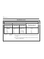
* Accuracy is given as ±([% of reading] + [number] + [number of lease significant digits]) at 18°C to 28°C, with relative
humidity up to 90%, for a period of one year after calibration. In the 4 ½-digit mode, multiply the number of lease
significant digits (counts) by 10. AC conversions are ac-coupled, true rms responding, calibrated to the rms value of
a sine wave input, and valid from 5% to 100% of range. AC crest factor can be up to 3 at full scale, 6 at half scale.
For non-sinusoidal wave forms add -(2% Rdg +2% Fs) typical, for a crest factor up to 3.
** Below 10% of range, add 16 counts.
*** Below 10% of range, add 6 digits.
† The Fluke 87 is a True-RMS responding meter. The meter will display a reading (typically <25 digits) when the input
leads are shorted together in the AC functions which is caused by internal amplifier noise. The accuracy on the
Fluke 87 is not significantly affected by this internal offset when measuring inputs that are within 5% to 100% of the
selected range. When the RMS value of the two values (5% of range and internal offset) is calculated, the effect is
minimal as shown in the following example where 20.0 = 5% of 400 mV range, and 2.5 is the internal offset.
2
2
RMS = SQRT[(20.0) + (2.5) ] = 20.16
If you use the REL function to zero the display when using the AC functions, a constant error that is equal to the
internal offset will result.
‡ Frequency range: 1 kHz to 2.5 kHz.
36
Specifications
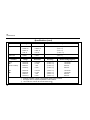
Specifications (cont)
Function
Range
Resolution
Accuracy*
L
4.000V
40.00 V
400.0 V
1000 V
0.001V
0.01 V
0.1 V
1V
±(0.1% + 1)
±(0.1% + 1)
±(0.1% + 1)
±(0.1% + 1)
F
mV
400.0 mV
0.1 mV
±(0.1% + 1)
e
400.0Ω
4.000 kΩ
40.00 kΩ
400.0 kΩ
4.000 MΩ
40.00 MΩ
40.00 nS
0.1Ω
0.001 kΩ
0.01 kΩ
0.1 kΩ
0.001 MΩ
0.01 MΩ
0.01 nS
±(0.2% + 2)**
±(0.2% + 1)
±(0.2% + 1)
±(0.6% + 1)
±(0.6% + 1)
±(1% + 3)
±(1% + 10)
(nS)
* See page 36 for a complete explanation of this notation.
** When using the REL ∆ function to compensate for offsets.
Typical Ohms Short Circuit Current
Range
400
4k
40k
400k
4M
40M
Current
200 µA
80 µA
12 µA
1.4 µA
.2 µA
.2 µA
37
87
Users Manual
Specifications (cont)
Function
Range
Resolution
Capacitance
5.00 nF
0.0500 µF
0.500 µF
5.00 µF
0.01 nF
0.0001 µF
0.001 µF
0.01 µF
±(1% + 3)
±(1% + 3)
±(1% + 3)
±(1.9% + 3)
Diode Test
3.000V
0.001V
±(2% + 1)
Function
Accuracy***
Range
Resolution
Accuracy*
Burden Voltage (typical)
mA †
\
(45 Hz to 2 kHz)
40.00 mA
400.0 mA
4000 mA
10.00A††
0.01 mA
0.1 mA
1 mA
0.01A
±(1.0% + 2)
±(1.0% + 2)
±(1.0% + 2)
±(1.0% + 2)
1.8 mV/mA
1.8 mV/mA
0.03 V/A
0.03 V/A
mA
[
40.00 mA
400.0 mA
4000 mA
10.00 A††
0.01 mA
0.1 mA
1 mA
0.01A
±(0.2% + 2)
±(0.2% + 2)
±(0.2% + 2)
±(0.2% + 2)
1.8 mV/mA
1.8 mV/mA
0.03 V/A
0.03 V/A
*** With film capacitor or better, using Relative mode to zero residual.
† See page 34 for a complete explanation of this notation.
†† 10A continuous, 20A for 30 seconds maximum.W
38
Specifications
Specifications (cont)
Function
Range
Resolution
Accuracy
Burden Voltage (typical)
B†
µA
(45 Hz to 2 kHz)
400.0 µA
4000 µA
0.1 µA
1 µA
±(1.0% + 2)
±(1.0% + 2)
100 µV/µA
100 µV/µA
F
µA
400.0 µA
4000 µA
0.1 µA
1 µA
±(0.2% + 3)
±(0.2% + 2)
100 µV/µA
100 µV/µA
Function
Frequency
(0.5 Hz to 200 kHz, pulse
width >2 µs)
Range
Resolution
Accuracy
199.99
1999.9
19.999 kHz
199.99 kHz
>200 kHz
0.01 Hz
0.1 Hz
0.001 kHz
0.01 kHz
0.1 kHz
±(0.005% + 1)
±(0.005% + 1)
±(0.005% + 1)
±(0.005% + 1)
Unspecified
† See page 36 for a complete explanation of this notation.
39
87
Users Manual
Specifications (cont)
Frequency Counter Sensitivity and Trigger Level
Input Range
(Maximum input for
specified accuracy =
10X Range or 1000V)
400 mV dc
400 mV dc
4V
40V
400V
1000V
Duty Cycle
Minimum Sensitivity (RMS Sinewave)
5 Hz - 20 kHz
70 mV (to 400 Hz)
150 mV
0.3V
3V
30V
300V
0.5 Hz - 200 kHz
70 mV (to 400 Hz)
150 mV
0.7V
7V (≤140 kHz)
70V (≤14.0 kHz)
700V (≤1.4 kHz)
Approximate Trigger Level
(DC Voltage Function)
40 mV
1.7V
4V
40V
400V
0.0 to 99.9%
Accuracy:
Within ±(0.05% per kHz + 0.1%) of full scale for a 5V logic family input on the 4V
dc range.
Within ±((0.06 x Voltage Range/Input Voltage) x 100%) of full scale for sine wave
inputs on ac voltage ranges.
40
Specifications
Specifications (cont)
Overload
Protection†
Input
Impedance
(nominal)
Common Mode Rejection
Ratio (1 kΩ unbalance)
Normal Mode Rejection
L
1000V rms
10 MΩ<100 pF
>120 dB at dc, 50 Hz or 60 Hz
>60 dB at 50 Hz or 60 Hz
F
mV
1000V rms
10 MΩ<100 pF
>120 dB at dc, 50 Hz or 60 Hz
>60 dB at 50 Hz or 60 Hz
K
1000V rms
10 MΩ<100 pF
(ac-coupled)
>60 dBc dc to 60 Hz
Function
Full Scale Voltage
Open Circuit
Test Voltage
To 4.0 MΩ
40 MΩ or nS
Short Circuit
Current
<450 mV dc
<1.3V dc
<200 µA
e
1000V rms
<1.3V dc
Diode Test
1000V rms
<3.9V dc
3.000V dc
0.6 mA typical
6
† 10 V Hz max
41
87
Users Manual
Specifications (cont)
Nominal Response
MIN MAX
Recording
100 ms to 80%
(DC Functions)
Specified accuracy ±12 digits for changes >200 ms in duration.
120 ms to 80%
(AC Functions)
Specified accuracy ±40 digits for changes >350 ms and inputs >25%
of range.
1s
Same as specified accuracy for changes >2 seconds in duration.
1 ms
Specified accuracy ±40 digits for changes >1 ms in duration.
(±100 digits typical for mv, 400 µA dc, 40 mA dc, 4000 mA dc.
WFuse Protection
mA or µA
A
42
Accuracy
44/100A, 1000V FAST Fuse
11A, 1000V FAST Fuse
Maximum Voltage between any Terminal and Earth Ground
1000V rms
Specifications
Specifications (cont)
Display
Operating Temperature
Storage Temperature
Temperature Coefficient
Electromagnetic Compatibility
Relative Humidity
Battery Type
Battery Life
Shock Vibration
Size (HxWxL)
With Holster and Flex-Stand:
Weight
With Holster and Flex-Stand:
Safety
Digital: 4000 counts updates 4/sec
19,999 counts (4½-digit mode), updates 1/sec
Analog: 4 x 32 segments (equivalent to 128), updates 40/sec
Frequency: 19,999 counts, updates 3/sec @ >10 Hz
Backlight: On for 68 seconds when selected.
-20°C to 55°C
-40°C to 60°C
0.05 x (specified accuracy)/ °C (<18°C or >28°C)
In an RF field of 1 V/m on all ranges and functions except capacitance:
Total Accuracy = Specified Accuracy + 2.5% of range.
Capacitance not specified.
Performance above 1 V/m is not specified.
0% to 90% (0°C to 35°C)
0% to 70% (35°C to 55°C)
9V, NEDA 1604 or 6F22 or 006P
400 hrs typical with alkaline
Per MIL-T-28800 for a Class 2 instrument
1.25 in x 3.41 in x 7.35 in (3.1 cm x 8.6 cm x 18.6 cm)
2.06 in x 3.86 in x 7.93 in (5.2 cm x 9.8 cm x 20.1 cm)
12.5 oz (355g)
22.0 oz (624g)
Designed to comply with IEC 1010-1 as a 1000V, CAT III instrument (see pg.2 for
definition of CAT III). UL listed to UL3111, TUV licensed to EN 61010-1, CSA 22.2
No. 1010.1:1992.
43
87
Users Manual
44