1
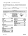
Neptune Front Load Washer⎯Technical Information
MAH7500*
• Due to possibility of personal injury or property damage, always contact an authorized technician for servicing or
repair of this unit.
• Refer to Service Manual 16010061 for detailed installation, operating, testing, troubleshooting, and disassembly
instructions.
!
CAUTION
All safety information must be followed as provided in Service Manual 16010061.
!
WARNING
To avoid risk of electrical shock, personal injury or death; disconnect power to washer before servicing, unless
testing requires power.
Service Technician Please Note:
Access diagnostic codes through Service Mode before beginning repair.
SERVICE MODE
The Service Mode provides service personnel the ability
to verify the operation of the washing machine. The
Service Mode can be entered at any time. While in the
Service Mode, the servicer can start special service
tests such as a service cycle. While in the Service
Mode, menus can be displayed and a variety of other
information about the machine can be accessed.
Press the “diagnostic code” on the touch screen to see
all of the diagnostic codes that have been logged. See
the following table for their descriptions, triggers and
actions to be taken.
DIAGNOSTIC CODES
Diag
Description
Trigger
Code
The water level
failed to drop
1 No Drain
below the low
water level in a
final spin.
The door
Door failed to
2 fails to
unlock after 11
unlock
attempts.
Continuous fill
of 12 minutes
3 No fill
or total fill of 14
minutes.
Door failed to
The door
lock after 11
4
fails to lock
attempts.
Continuous
unbalance Unbalance
5 circuit
circuit is always
(During Spin open.
only).
Motor did not
turn after 10
6 Locked rotor
consecutive
retry attempts.
ACCESSING SERVICE MODE
Press and hold the “back” and “help” keys for 3
seconds to start the Service Mode. The following
information will appear on the touch screen.
December 2004
©2004 Maytag Services
Action to be Taken
Go to “Will Not
Drain”, page 4.
Go to “Will Not
Unlock”, page 4
Go to “No Water
Fill”, page 3.
Go To “Will Not
Lock”, page 3.
Go to “Wet
Clothes”, page 3.
(See unbalance
harness
connections)
Go to “Motor Drive
System Test”.
1
16025823
Diagnostic Codes
!
WARNING
To avoid risk of electrical shock, personal injury, or death, disconnect power to washer before servicing, unless
testing requires it.
Diag
Description
Code
Trigger
Temperature
rise not
Heater not
detected when
7
heating
heater was on
for 10 minutes.
The low water
level is not
satisfied before
Water
the high water
8 sensor level
level contacts
fault
are opened in
the pressure
switch.
9 (Not Used)
Did not reach
Low RPM
500 RPM due
10 unbalanced to an
load
unbalanced
load.
Non-volatile Difficulty in
11 memory
reading
error
memory
Diag
Description
Code
Action to be Taken
Check heater and
sump thermistor for
continuity. Was
heater on with no
water fill?
Action to be Taken
1. Customer may
have tried to
The door has
repeat wash cycle
not been
without opening
opened after a
door.
complete wash
2. Go to “Door
cycle.
Lock Test”, page
6
1.Clear the
Door lock
diagnostic code;
Door lock
switch is
recheck.
detected
detected as
open during
2. Go to “Door
open with
cycle.
Lock Test”, page
motor running
6
(Not Used)
Door switch is
detected as
Check harness
Door switch
open and the
connections at door
detected
door lock
open/closed switch
open during
switch is
and for switch
cycle.
perceived as
continuity.
locked.
Door is
Door lock is
locked at
locked and user Go to “Will not
start of
tries to start a Unlock”, page 4
cycle.
cycle.
Motor tach
Motor over signal detected Replace Motor
speed
at maximum
Control Board
speed.
Clear diagnostic
Motor tach
Tach signal
codes; possible line
signal exists
exists without noise issue. If
without
torque
problem persists,
motor
command.
replace Motor
running.
Control Board
(Not Used)
Abnormal
Go to “Wrong
Valve
high/low
Water
thermistor
temperature or
Temperature”,
failure
ohm resistance
page 4
detected.
Abnormally
Check harness
Sump
high/low
connections, check
thermistor
temperature or
continuity of sump
failure
ohm resistance
themistor.
detected.
Unlock
Conditions for Go to “Will Not
problem
unlock not met. Unlock”.
Door
actuator
switch was
17 not detected
open since
the final
spin.
Go to “No Fill
Test”, page 6
18
19-21
Go to “Wet
Clothes”, page 3
22
1. Unplug and
reconnect power
cord at power
supply outlet.
2. If condition still
exists, replace
Machine Control
Board.
23
12-14 (Not Used)
24
A key is sensed
to be pressed
for more than Replace Membrane
15 Stuck key
75 seconds, the switch.
key is assumed
to be stuck.
Speed never
exceeded 500
RPM during a
High speed
main wash
not achieved
cycle.
Go to “Wet
16 due to high
Experienced
Clothes”, page 3
motor
maximum
torque.
torque for
extended
period.
25
26-27
28
29
62
16025823
Trigger
2
December 2004
©2004 Maytag Services
Troubleshooting
!
WARNING
To avoid risk of electrical shock, personal injury, or death, disconnect power to washer before servicing, unless
testing requires it.
•
Note: If any “unused codes” appear on the screen,
disregard these codes. This is normal. The non-listed
codes are insignificant codes.
•
TROUBLESHOOTING THE SYMPTOMS
•
Leaking
• Make sure supply hose connections are not
leaking. Check for rubber gasket damage due to
over tightening.
• Make sure end of drain hose is correctly
inserted and secured to drain facility.
• Avoid overloading which can push the door
partially open.
• Check internal hose connections
• Check tub cover. Remove, reposition and
reinstall the tub cover seal. Seal seam must be
at the top of the tub cover.
•
Check that the leveling leg lock nuts are
tightened.
If complaint is a high-pitched noise during fill
then disconnect supply hoses and clean
screens.
Check for proper spring placement of outer tub
support springs.
Check strut operation.
Tub is completely full of suds
• Run the clothes washer through another
complete cycle using cold water and no more
detergent.
• Reduce detergent amount in the future for that
specific load size and soil level. Towel loads
have a minimal amount of soil present and
typically create more suds.
• Use high efficiency or low sudsing detergent
specially formulated for front load washers.
• Check for restricted drain system.
• Check for loose wire connections at Control
Board and Drain Pump.
• Check to see if belt is off motor and pulley.
• Perform “Motor Drive System Test”.
Display Lights Up When Door Opened
• This is normal behavior.
No Tumble
• Washer does not tumble for the first 30 seconds
after the door has been opened for safety
purposes.
• Fabric cycles such as DELICATES and HAND
WASH only tumble for a few seconds every 30
seconds.
• Check for loose connections at Machine Control
Board, Motor Control Board and Motor.
• Perform “Motor Drive System Test”.
• Washer does not tumble during some drains
and rinse fills.
Wet Clothes
• Very small clothes loads can cause unbalances.
Add additional towels.
• Excessive suds may have been present. Check
for diagnostic code 16.
• Check unbalance harness connections at all
switches and at main harness connection on top
of Outer Tub Assembly for connectivity.
• Inertial Unbalance Switch tripped too soon,
resulting in lower spin speeds. Run Quick Spin
Test to check unbalance switches and Control
Board.
• Check for restricted drain system.
• Perform “Motor Drive System Test”.
No Water Fill
• Check to make sure water supply is fully turned
on. Normal water level is only 2.5 to 5 inches
inside and toward the rear of the spinner.
• Check for kinks in inlet hoses.
• Check for clogged inlet screens.
• Visually check hot and cold separately at
dispenser for proper flows.
• Perform “No Fill Test” page 6.
Will Not Lock
• Check to see if the door is closed.
• Check electrical connections at lock assembly
and Machine Control Board. Perform “Door
Lock Test”.
Noisy
• Clothes washer should be leveled properly as
outlined in installation instructions.
• Weak floors can cause vibration and walking.
• Check for loose lower front weight
• Verify rubber feet are installed on leveling legs.
December 2004
©2004 Maytag Services
3
16025823
Troubleshooting
!
WARNING
To avoid risk of electrical shock, personal injury, or death, disconnect power to washer before servicing, unless
testing requires it.
incorrectly and then corrected, the washer will
need to run through a Hot / Cold cycle. If not
resolved, check for proper resistance on the
water valve thermistor. (See Board
Input/Output Chart; pages 7-8).
Will Not Unlock
• Unplug and reconnect the power cord. Wait 2
minutes to see if machine unlocks.
• Check for door locked switch circuit to be closed
at Machine Control. (See Board Input/Output
Chart, pages 7-8).
• Check to make sure belt has not fallen off.
• Check for loose electrical connections at door
lock and at Machine Control Board.
• Perform “Motor Drive System Test”.
Diagnostic Tests
Touching any of the screens on the washer control
panel will initiate the corresponding test.
Will Not Start
• Plug cord into live electrical outlet.
• Check fuse or reset circuit breaker.
• Push the “off” button then open and close the
door. Push the “start/pause” button to start the
clothes washer.
• Check to see if the washer is in a pause or soak
period in the cycle. Wait briefly for cycle to
change.
• Check for restricted drain system.
Will Not Drain
• Check for restricted drain system.
• Check low and high water levels. Perform “No
Fill Test”
• Check for 120 VAC at the pump when a spin
cycle is selected.
User Interface Tests
This test will check the touch screen and the membrane
pad. The technician will be prompted what to do.
Wrong Water Temperature
• Too Hot/Too Cold- since this product uses a low
amount of water, the board regulates the
incoming flow to temper the actual temperature
of the water in the tub. This may appear to be
significantly warmer/cooler than expected.
• Are both faucets turned ON fully?
• Make sure temperature selection is correct.
• Make sure hoses are connected to correct
faucets and inlet connections. Flush water line
before filling washer.
• Check the owner’s water heater. It should be set
to deliver a minimum 120°F (49°C) hot water at
the tap. Also check water heater capacity and
recovery rate.
• If the water heater is located a long distance
from washer, water line may need to be purged
prior to starting wash cycle.
• Disconnect inlet hoses and clean screens.
• This washer can sense if the fill hoses have
been reversed between hot and cold. If the fill
hoses on the washer were previously installed
16025823
Service Cycle
The Service Cycle is used to run a quick cycle that
performs all of the normal wash cycle functions.
Initiating a Service Cycle: If the washer is not
operating in a wash cycle, touch the button “service
cycle“ to begin the Service Cycle.
During a wash cycle:
Press the “service cycle” button; then cancel the wash
cycle, and start the washer in the Service Cycle. If the
washer is running during Service Cycle the screen will
display the various inputs and outputs of the washer.
System Check
(See System Check) will allow you to perform system
checks of the various inputs and outputs of the washer.
Advance To Next Step
Selecting “advance to next step” button advances the
cycle to the next step in the cycle.
4
December 2004
©2004 Maytag Services
Troubleshooting
!
WARNING
To avoid risk of electrical shock, personal injury, or death, disconnect power to washer before servicing, unless
testing requires it.
Quick Spin Test
To begin test, select “quick spin test” button. The
washer will display the following during the test:
“Static Drain”
“Spin to 350 RPM”
“Spin to 550 RPM”
“Spin to 600 RPM”
“Spin to 650 RPM”
“Spin to 800 RPM”
“Spin to 1000 RPM”
“Coast down and unlock at 0 RPM”
“Quick Spin Test complete”
3. Reconnect the washer power cord to supply voltage.
4. Press and hold the “help” and “back” keys for 3
seconds to start the Service Mode.
5. Select “system check”; touch “toggle motor
control on”.
6. The Motor Control will immediately execute a test
routine and the motor should run, rotating the
spinner at 50 rpm.
7. If the motor runs, and the spinner rotates at the
proper RPM: the problem lies outside of the motor
and Motor Control Circuit.
8. If the motor runs, but the spinner does not rotate:
Check for missing belt.
9. Verify 120VAC at L1 and N connection at Motor
Control Board.
10. If voltage is present, then problem lies with the
motor and Motor Control System.
11. Disconnect power to the washer and reconnect the
JP4 Interface connector to the Motor Control.
12. Check for loose electrical connections at motor, and
Motor Control Board.
13. Check phase windings of the motor.
Any of the steps in this test can be held or paused up to
30 minutes, by touching the “hold at this step” button.
“cancel & exit quick spin test,” returns you to the
Service Tests screen.
Motor Drive System Test
Perform a Motor and Motor Control Test.
Motor & Motor Control Test
1. Disconnect power to the washer.
2. Remove the front panel and pull the JP4 Connector
from the Motor Control Board.
14. If motor windings are good, replace the Motor
Control Board.
If voltage is not present;
15. Check loose electrical connections at Machine
Control Board or broken wires in harness.
16. Check door actuator switch and related wiring.
December 2004
©2004 Maytag Services
5
16025823
Troubleshooting
!
WARNING
To avoid risk of electrical shock, personal injury, or death, disconnect power to washer before servicing, unless
testing requires it.
Door Lock/Unlock Test
Note: The relay on the Control Board for the door unlock
mechanism is disabled if the Motor Control Board
indicates the spinner speed is > 7 RPM.
6.
7.
Door Unlock Test
1. Press “off”; verify the Door Lock/Unlock
solenoid harness connections are not loose and
wiring is correct. Does the door unlock?
2. Disconnect power to the washer and perform a
continuity check between Conn P8(3) of the
Machine Control Board and the Neutral prong
on the power cord. There should be continuity.
8.
9.
Door Lock Test
1. Start a “system check cycle”; verify the Door
Lock/Unlock solenoid harness connections are
not loose and wiring is correct. Does the door
lock?
2. Disconnect power to the washer and perform a
continuity check between Conn P1(1) of the
Machine Control Board and the Neutral prong
on the power cord. There should be continuity.
10.
No Fill Test
1. Verify that the cold and hot water supplies at the
faucet are turned on and can supply water.
2. Remove the hoses and clean out any debris
from both ends and the hot and cold water
valves.
3. Close the door and start a “spin cycle” to drain
all water from the washer to reset the Pressure
Switch.
4. Press “off” and open the door to verify that all
water is removed from the washer. If water is
still present, Go to page 4.
5. If water is drained out, close the door and enter
“service mode” (press “help” and “back” for 3
16025823
6
11.
12.
seconds). Obtain access to the Water Valve,
Pressure Switch, and Control Board for voltage
checks by raising the Top Cover and loosening
the Console now. Make sure the door is closed.
Enter the System Check mode by pressing the
appropriate button on the touch panel. The door
should lock when System Check mode is
entered.
Verify that the low water level is empty ("wash
level (low) empty"). If the low level is full, check
the low water level input at the Control Board
connector by reading the DC voltage between
P3(5) and P3(3). If more than 2VDC, check the
voltage at the Pressure Switch between the BU
and the BR wires. If more than 2VDC, replace
the Pressure Switch. If voltage is not present at
the Pressure Switch, check or replace the wire
harness. If no voltage is present at the Control
Board, replace the Control Board.
If the low water level is shown as empty, verify
that the door is sensed closed. The Control
Board cannot sense the high water level with the
door open.
Verify that the high water level is empty ("rinse
level (high) empty"). If the high level is full,
check the high water level input at the Control
Board connector by reading the AC voltage
between P1(8) and P8(2). If less than 60VAC,
check the continuity at the Pressure Switch
between the GY and YL wires. If no continuity,
replace the Pressure Switch. If there is
continuity, check or replace the wire harness. If
more than 60VAC is present at the Control
Board, replace the Control Board.
If the high water level is shown as empty, turn
the Cold Water Valve on by pressing the “toggle
cold” button. Verify that cold water is flowing in
the dispenser. If it is not flowing, check the ColdWater Valve for 120VAC between the BU and
WH wires. If 120VAC is not present at the cold
valve, check for 120VAC at the Control Board
between P1(4) and P8(2). If 120VAC is present
at the Control Board, check or replace the wire
harness. If 120VAC is not present at the Control
Board, replace the Control Board. If cold water
flows, turn the cold valve off by pressing the
“toggle cold” button.
Drain all of the water out of the washer by
pressing the “toggle drain” button until drained,
then turn the drain off.
Turn the Hot Water Valve on by pressing the
December 2004
©2004 Maytag Services
Troubleshooting
!
WARNING
To avoid risk of electrical shock, personal injury, or death, disconnect power to washer before servicing, unless
testing requires it.
“toggle hot” button. Verify that hot water is
flowing in the dispenser. If it is not flowing,
check the Hot Water Valve for 120VAC between
the OR and WH wires. If 120VAC is not present
at the hot valve, check for 120VAC at the
Control Board between P1(3) and P8(2). If
120VAC is present at the Control Board, check
or replace the wire harness. If 120VAC is not
present at the Control Board, replace the
Control Board. If hot water flows, turn the hot
valve off by pressing the “toggle hot” button.
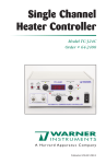
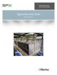
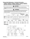
Machine Control Board Input/Outputs
LCD Washer Control Board
When testing any 24 VDC circuit
you must use connection P2 (3)
As a neutral reference.
System Check
System Checks can be initiated at any time. If the
washer is not in a wash cycle, the following screen will
display and allow the technician to toggle various
components On/Off.
The MAH7500 Machine Control Boards low voltage DC
outputs are isolated from the 120V circuitry.
Screen with washer in a wash cycle:
Neutral from the incoming line cannot be used to
achieve a valid 24VDC reading.
Board Input/Output Chart
Descr.
Bleach
water valve
output
Cold water
valve output
Door Lock
output
Screen with the washer not in a wash cycle:
Door Lock
switch input
Door switch
input
Door Unlock
output
Drain pump
output
HeaterNeutral
High water
level - input
Hot water
valve output
December 2004
©2004 Maytag Services
Conn/
Reference
Pin
To Conn/
Voltage Comments
Number Pin
Number
P1(5)
P8(2)
120
VAC
P1(4)
P8(2)
120
VAC
P1 (1)
P8 (2)
120
VAC
P3 (8)
P2 (3)
24VDC
P8 (1)
P8 (2)
120
VAC
P8 (3)
P8 (2)
120
VAC
P6 (4)
P8 (2)
P6 (1)
P8 (1)
P1 (8)
P8 (2)
P1 (3)
P8 (2)
120
VAC
120
VAC
120
VAC
120
VAC
500-1K
ohms
60
millisecond
pulse
Locked;
24VDC
Closed;
120VAC
60
millisecond
pulse
500-1K
ohms
7
16025823
Troubleshooting
!
WARNING
To avoid risk of electrical shock, personal injury, or death, disconnect power to washer before servicing, unless
testing requires it.
Descr.
L1 to
machine
control
board
L1 to motor
control
Lower water
level - input
Motor
control tach
Neutral (120
VAC)
Unbalance
input
Softener
water valve
Sump Heater
Thermistor
Torque
PWM
Water valve
thermistor
Conn/
Reference
Pin
To Conn/
Voltage Comments
Number Pin
Number
P6 (2)
P8 (2)
120
VAC
P6 (3)
P8 (2)
120
VAC
P3 (5)
P2 (3)
24VDC
P2 (1)
P2 (3)
24VDC
P8 (2)
Empty;
24VDC
Neutral
No
unbalance
24VDC
condition;
24VDC
120
VAC
P3 (2)
P2 (3)
P1 (6)
P8 (2)
P5(3)
P5(4)
1-5VDC
P2(2)
P2(3)
24VDC
P3(6)
P3(7)
1-5VDC
Dependent
on
temperature
NTC
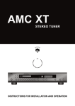
MEMBRANE PAD CHECKS
Check the Membrane Pad, by pulling the P7 connector
from the Machine Control Board and locating the
corresponding switch pin numbers in the ribbon harness.
There should be <100 ohms present when the pad is
pressed.
Membrane Pad
home
favorites
back
start/pause
off
help
16025823
Pin Number
P7 (3)
P7 (4)
P7 (3)
P7 (3)
P7 (4)
P7 (4)
Pin Number
P7 (5)
P7 (5)
P7 (6)
P7 (7)
P7 (7)
P7 (6)
8
December 2004
©2004 Maytag Services
Troubleshooting
!
WARNING
To avoid risk of electrical shock, personal injury, or death, disconnect power to washer before servicing, unless
testing requires it.
HELP CODE TABLES
Help
Code
Description
Trigger
Plaster Unbalance Load
Detected.
Unbalance load
condition existed
during initial
ramp up of spin
cycle. Resulted
in redistribution
cycle.
(Not Used)
Low water level
contacts of
Pressure Switch
not seen as
resetting at end
of drain cycle.
During startup,
the Spinner did
not reach 10
rpm within 2
sec. (During
Wash/Tumble).
Water Valve
Thermistor
readings are
contrary to what
is being
demanded by
washer Control
Board.
Locked rotor
condition during
a spin
(Not Used)
Motor on at full
power for 30
seconds at >850
rpm.
Opening of
Unbalance
Switches at
speed <500 rpm
and >100 rpm
during a spin.
Opening of
Unbalance
Switches at
speed >850 rpm
and during a
final spin.
1
2-6
Slow drain
7
One locked rotor
8
Fill hoses are reversed.
9
10
Locked rotor condition
during a spin.
11
12
Too much power at
speed >850 rpm
Low Speed Unbalance
Detected.
13
High Speed Unbalance
Detected
14
December 2004
©2004 Maytag Services
Action To Be Taken
Informative only; non-critical
condition
Check for restricted drain
system, kinked/plugged drain
hose or pump. Check pump for
proper function. May see
diagnostic code 01.
Informative only; non-critical
condition.
Inlet hoses reversed at the
faucets for Hot and Cold.
Informative only; non-critical
condition.
Informative only; non-critical
condition.
Informative only; non-critical
condition.
Informative only; non-critical
condition.
9
16025823
Troubleshooting
!
WARNING
To avoid risk of electrical shock, personal injury, or death, disconnect power to washer before servicing, unless
testing requires it.
15
Spin suds lock
16
High speed unbalance
detected.
17
18
Power down
(Not Used)
Suds lock, full
power given to
motor by Motor
Control Board
for 1 second
within a spin at
less than 500
RPM; for
example during
the spin cycle.
Opening of
Unbalance
Switches at
speed >500
RPM and during
a final spin.
(Not Used)
Loss of power.
19
20
Fast fill
21
22
23
Too Much Power At 550
- 850 rpm.
2429
33
Control Board
detects motor
torque dropping.
Too much power at start
of spin.
Maximum torque
requested in
Spin Less Than
110 RPM.
Too much power during
Wash/Tumble.
Maximum torque
requested in
Wash/Tumble.
16025823
Informative Only
Will indicate power failure until
a key is pressed. If a cycle was
in process prior to loss of
power, then pressing
“start/pause” key will resume
cycle and clear the "PF"
display.
Possible slow drain scenario
present or customer interrupted
wash cycle and started washer
over again. Check for
Diagnostic Code 08.
(Not Used)
Motor on at full
Informative Only
power too long
between 550 850 rpm.
(Not Used)
Excessive Suds
Detected During
Wash/Tumble.
34
35
(Not Used)
Fill level
reached within 2
seconds of fill
initiation.
Too much detergent; non-HE
detergent with suds suppressor
being used; washing clothes
with minimal amount of soils
present with normal measure
amount of detergent.
Too much detergent; non-HE
detergent with suds suppressor
being used; washing clothes
with minimal amount of soils
present with normal measure
amount of detergent.
Perform Motor Drive System
Test. Check wire harness.
Perform connections at Motor,
Motor Control Board (JP4
connector) and Machine
Control Board connections.
Perform Motor Drive System
Test. Check wire harness
connections at Motor, Motor
10
December 2004
©2004 Maytag Services
Troubleshooting
!
WARNING
To avoid risk of electrical shock, personal injury, or death, disconnect power to washer before servicing, unless
testing requires it.
36
37
Motor still running after
240 seconds of coast
down after a spin.
Motor running during
tumble for too long.
3839
Motor running
>85 RPM and
the door is not
locked.
Loss of Tach Signal
during door unlock
sequence.
Cycle was
paused due to
failure to verify
Tach Signal
during unlock
request.
Cycle was
paused because
Motor Control
not powered
during unlock
request.
Cycle was
paused because
the Tach
occurred when
the Motor
Control was
powered during
unlock request.
No Tach Signal
observed when
Motor Control is
powered at the
end of the failed
fast power up
and unlock
retries.
Motor Control Not
Powered During Unlock.
42
Tach Signal
unexpectedly present
during unlock.
43
44
45
Motor still
running after
240 seconds of
coast down after
a spin.
1 minute after
Informative only
start of tumble, if
speed is > 85
RPM.
(Not Used)
The door Is not locked
while spinning.
40
41
Control Board (JP4 connector)
and Machine Control Board
connections.
Informative only
Unlocking attempts
disallowed because
Tach Signal continues
after Tach verification.
Door locked when not
expected.
Cabinet impact sensed.
46
December 2004
©2004 Maytag Services
Cabinet impact
detected by the
frame vibration
Perform Motor Drive System
Test. Check wire harness.
Perform connections at Motor,
Motor Control Board (JP4
connector) and Machine
Control Board connections.
Informative only; Refer to
Diagnostic code 62
Informative only; Refer to
Diagnostic code 62
Informative only; Refer to
Diagnostic code 62
Informative only; Refer to
Diagnostic code 02
Check Door Lock Switch for
welded contacts.
Informative only
11
16025823
Troubleshooting
!
WARNING
To avoid risk of electrical shock, personal injury, or death, disconnect power to washer before servicing, unless
testing requires it.
Door did not lock after
the first try.
47
Door did not unlock after
the first try.
48
16025823
sensor.
The Door Lock
Switch did not
go from
unlocked to
locked when the
door lock output
was energized.
The Door Lock
Switch did not
go from locked
to unlocked
when the door
unlock output
was energized.
Informative Only
Informative Only
12
December 2004
©2004 Maytag Services
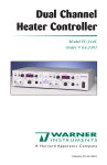
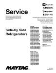
Wiring Diagram
!
WARNING
To avoid risk of electrical shock, personal injury, or death, disconnect power to washer before servicing, unless
testing requires it.
December 2004
©2004 Maytag Services
13
16025823