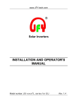
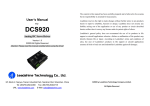
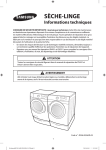
1
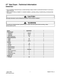
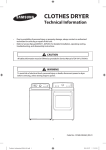
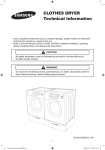
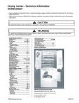
27” Domestic Dryer⎯Technical Information
MDE6700A*, MDG6700A*
• Due to possibility of personal injury or property damage, always contact an authorized technician for servicing or
repair of this unit.
• Refer to Service Manual 16026446 for detailed installation, operating, testing, troubleshooting, and disassembly
instructions.
!
CAUTION
All safety information must be followed as provided in Service Manual 16026446.
!
WARNING
To avoid risk of electrical shock, personal injury or death; disconnect power to dryer before servicing, unless
testing requires power.
September 2006
©2006 Maytag Services
1
16026881
RPL 16026540
Troubleshooting Procedures
!
WARNING
To avoid risk of electrical shock, personal injury or death; disconnect power to dryer before servicing, unless
testing requires power.
Will Not Run
Will not start or run:
• All wires are hooked up to their corresponding
terminals.
• Dryer is plugged in.
• Blown fuse or circuit breaker.
• Door switch functional...door closed. Check for
error code 3 (See Table for code definition).
• Start/Pause rotary selector dial functional.
• Control Board operational.
• Drive motor functional.
• Check motor winding resistance: 2.88ohms
between pin #3 and 4, 3.5ohms between pin #4
and 5.
Will Not Dry Gas Models
Poor Gas Ignition
When the dryer is operated on a heat setting, the
igniter should be energized and burner shall fire within
45 seconds at 120 VAC. The failure of a component in
this system will usually be indicated by one of three
symptoms:
The igniter does not glow. If the igniter does not
heat up, remove power and using an ohmmeter,
check the following:
• Open flame sensor
• Open igniter
• Shorted booster coil
• Open wiring
• Bad motor switch ( Neutral supply)
• No power from control ( L1 supply)
Igniter glows - No gas ignition. If the igniter heats
up but the main burner flame is not ignited, remove
power and using an ohmmeter, check the following:
• Open secondary coil
• Open holding coil
• Open wire harness
• Stuck flame sensor (Stuck closed)
The gas is ignited but the flame goes out. If a
normal ignition takes place and after a short while the
flame goes out, check for the following:
• Radiant sensor contacts opening
prematurely.
• Weak gas valve coil may open when
stressed by higher temperatures.
• Weak Hi-Limit
• Poor venting
• Bad drum seals
Motor runs/ tumbler will not turn:
• Belt off or broken/damaged.
• Idler tension spring too weak or stretched.
• Idler pulley jammed or stuck.
Runs a few minutes and then stops:
• Lint buildup around drive motor.
• Low voltage present.
• Blower impeller blocked in blower
housing.
• Drive motor - start switch contacts stuck closed.
Blows fuses or trips circuit breaker:
• The amperage readings are at 240 volts. One line
will be 24 amps and the other line will be 21 amps.
The neutral line will be at 3 amps. If the above
amperages are present, then the house wiring,
fuse box or circuit breaker should be suspect.
• Shorted heating element to housing.
• Incorrect wiring or a wire shorting to ground.
• Drive motor winding shorting to ground.
Gas Models
• During ignition the dryer will draw X amps. With the
burner ON, the dryer will draw X amps. If the dryer
is drawing amperages above this, then the house
wiring, fuse box or circuit breaker is suspected to
be at fault.
• Igniter harness loose and shorted to base.
• Incorrect wiring or wire shorted to ground.
• Drive motor winding shorting to ground.
Improper drying/clothes wrinkled/ rough
texture/long dry time:
• Lint filter is not clean.
• Restriction in exhaust.
• Outside exhaust hood damper door stuck closed.
• Exhaust too long, too many elbows, flex ductwork
installed.
• Poor intake air available for the dryer.
• Incorrect tumbler speed. Tumbler belt slipping.
• Blower impeller bound; check for foreign material
in blower area.
• Customer overloading dryer.
• Check clothing labels for fabric content and cycle
selected.
• Clothes too wet due to insufficient spin out by
washer.
Will Not Dry
Will not heat (motor runs):
• Open heating element.
• Hi-Limit trips easily or is open.
• Regulating thermostat trips easily or is open.
• Membrane switch open.
• Check Thermistor.
September 2006
©2006 Maytag Services
2
16026881
RPL 16026540
Troubleshooting Procedures
!
WARNING
To avoid risk of electrical shock, personal injury or death; disconnect power to dryer before servicing, unless
testing requires power.
Key Press
Will Not Shut Off
• Check Membrane Pad.
• Check Electronic Control Board.
• Short in sensor circuit.
Wrinkle Prevent
Displays “d”
Troubleshooting the electronic
control circuit:
• Check for miswiring of the electrical connector at
the electronic control board.
Noisy and/Or Vibration
• Thumping Check for loose tumbler baffle, rear
tumbler roller(s) worn or misaligned, out-of-round
tumbler or high weld seam on tumbler.
• Ticking Check for loose wire harness or object
caught in blower wheel area.
• Scraping Check for front or rear bulkhead felt seal
out of position or worn tumbler front bearings.
• Roaring Check for blower wheel rubbing on blower
housing or bad motor bearings.
• Popping or squealing sound. Check for a sticky
or frayed belt.
To sequence thru
the diagnostic
and help codes.
Temperature Key
Display software
revision number
Start or pause
cycle running but
remain in
diagnostic mode.
Display the
number of cycles
ago the
diagnostic code
occurred.
System Check Mode
While in Service Mode, pressing the
Time and Wrinkle Prevent keys for 3 seconds, will
put the dryer into the System Check mode and "in"
will display. The following table lists the various
functions based on the keys being pressed.
This mode provides Service Personnel the ability to
verify the operation of the dryer.
The Service Mode can be implemented at any time,
including the middle of a dry cycle. While in the
Service Mode, the Technician can start special
diagnostic tests such as a System Check Mode, LED
Switch/Check, Display Software version number and
display diagnostic/help code listings.
System Check Mode Table
Key Pressed:
Start/Pause rotary
selector dial
Rotate the Cycle Selector
Knob to Delicates
Enter Service Mode:
Dryer must be on before Service Mode can be
entered. Press Chime and Temperature Keys for 3
seconds, or until 3 beeps are heard. The machine will
now be in Service Mode. Upon entry into Service
Mode, the Sensor Bar Touch Data is to be displayed.
Rotate the Cycle Selector
Knob to Sensor
Dry
Exit Service Mode
Press the OFF key to exit Service Mode or repeat the
Chime and Temperature sequence.
Diagnostic Tests
The following table lists the various tests available
while in the Service Mode. Before advancing to the
next test, the current test running must be terminated.
Press the following keys to access:
©2006 Maytag Services
Then rotate the Cycle
Selector Knob
Start/Pause
Service Mode
September 2006
Special
Test/Function
Display list of
diagnostic codes.
3
Function
Performed
Cycles the motor
on/off.
LED’s and 7
segment display
flash.
View current
cycle temperature
in Celsius.
Rotate the Cycle Selector
Knob to Wrinkle Control
Segment display
is “1” for sensor
bar short, “0” for
sensor bar open
Rotate the Cycle Selector
Knob to Time Dry
View current
cycle
temperature in
Fahrenheit.
16026881
RPL 16026540
Troubleshooting Procedures
!
WARNING
To avoid risk of electrical shock, personal injury, or death, disconnect power to dryer before servicing, unless
testing requires power.
turns the knob in the opposite direction, the more
recent code will be displayed.
LED/Switch Check
While in Service Mode, pressing the Chime and
Wrinkle Prevent keys for 3 seconds, will start a
LED/Switch Test. To exit the test at any point, press
the same keys again for 3 seconds or press the OFF
key to exit Service Mode.
While a diagnostic code is displayed, if the
Start/Pause button in the center of the Rotary Cycle
Selector is pressed and held, the machine will display
the number of cycles ago the diagnostic code
occurred. When the Start/Pause button is released,
the diagnostic code is again displayed.
Perform the check by pressing the keys which toggle
the LED’s on and off.
Clearing Diagnostic Codes
To clear the diagnostic code list press the Sensor Dry
Level and Time keypads together for 3 seconds while
viewing the list. The cycle count for each diagnostic
code will be reset to 0, but not the machine cycle
count.
All switch pads must be pressed within 5 minutes for
this test to pass. PA will be displayed for five (5)
seconds once all switch pads have been pressed and
this test is completed. Following 10 seconds of
inactivity at any point, the test will exit without any
display. The Power Off switch pad must be pressed
twice within thirty (30) seconds to cancel this test.
Switch
Action
Wrinkle Prevent
Chime
Adjust Time
Time
Temperature
Dryness Level
Selector Knob
Start Pause
Off
Press once
Press once
Press once
Press four times
Press twice
Press twice
Rotate 1 position
Press once
Press once
Diagnostic Codes
Code
1
2
Trigger
Action Taken
Dryer
Thermistor
Short Sensed
Description
The
Thermistor
resistance is
very low.
Thermistor
Open Sensed
The
Thermistor
resistance is
very high
Check for:
- Clogged lint
screen.
- Restricted vent
system.
- Check Thermistor
resistance.
Check for:
- Low ambient
temperature in
room (Below
º
º
50 F/10 C).
Outside vent
damper is stuck
open in wintertime.
- Loose or open
wire terminals.
- Check Thermistor
resistance.
Check for:
- Loose or open
wire terminals in
Door Sense
circuit.
Check for:
- Loose connections
in motor circuit.
- Run System
Check Mode and
check the motor
relay function.
- If relay functions,
disregard the
diagnostic code.
- If relay does not
function, replace
machine control
board.
-
Diagnostic Codes
The Diagnostic Codes are identified when the severity
level of the abnormality detected is higher and service
may be required.
When a problem with the dryer is detected a
Diagnostic Code is assigned, and can be displayed.
The Control Board will not log multiple same codes
per cycle; however, it will log as many Diagnostics as
possible for the machine to continue running.
Access Diagnostic Codes by entering the Service
Mode and pressing Wrinkle Prevent. A d will be
displayed.
Rotate the Cycle Selector Knob in either direction to
step through the list of codes one code at a time.
Once an initial direction is selected by the user (either
Clockwise or Counterclockwise), subsequent
movements of the knob in the same direction will
show older codes. If the user changes direction and
16026881
RPL 16026540
4
3
Door Circuit
Failure
Invalid state
for more
than 256
milliseconds
4
Possible motor
transistor error
If either
motor
transistor is
seen open or
shorted
during
startup
September 2006
©2006 Maytag Services
Troubleshooting Procedures
!
WARNING
To avoid risk of electrical shock, personal injury or death; disconnect power to dryer before servicing, unless
testing requires power.
Code
8
10
Description
Trigger
Action Taken
Stuck Key
A key is
sensed to be
pressed
more than
75 seconds,
the key shall
be assumed
to be stuck.
Run membrane pad
check and replace
console w/membrane
pad if necessary.
No Wet Clothes
Sensor
bar
detects no
wet
clothes
while a
Sensor
Dry
Cycle
Check for:
- Running dryer
with
no wet clothes in
sensor dry cycle
Display Fault/Error Codes
Display Description Trigger
tS
do
Dryer
Thermistor
Short
Sensed
Door Open
September 2006
©2006 Maytag Services
The
Thermistor
resistance is
very low.
Running the
dryer with
door open
FE
Power
source
frequency
Error
Invalid
power
source
frequency
Check for:
- Not using
regular
power
source
frequency
- Invalid
power
frequency
sense
circuit
dC
Door Circuit
Failure
Invalid state
for more
than
256
milliseconds
Check for:
- Loose or
open
wire
terminals in
Door Sense
circuit.
- Check for
diagnostic
code 3
hE
Heater Error
Invalid
heating
termperature
in running
the
dryer
Check for:
- Restricted
vent
system.
- Check
Thermistor
resistance.
Action
Taken
Check for:
- Clogged
lint
screen.
- Restricted
vent
system.
- Check
Thermistor
resistance.
- Check for
diagnostic
code 1
Component Electrical Testing
• Thermistor resistance 10K Ω @ 25°C 77°F
(2P-Blue & Red wire)
• Thermostat 1 resistance < 1Ω (White & Yellow wire)
Check for:
- Close the
door,
and run the
dryer
- Loose or
open
wire
terminals in
Door Sense
circuit.
- Check for
diagnostic
code 3
85¡C ,25A
thermal cut-off
5
• Thermostat 3 resistance < 1Ω (Red & Black wire)
-If resistance is infinity, replace thermostat 3.
• Thermostat 2 resistance < 1Ω (Blue & Black wire)
-If resistance is infinity, replace thermostat 2.
• Heater resistance 10 Ω (Blue & Blue wire)
-If resistance is infinity, replace Heater.
16026881
RPL 16026540
Troubleshooting Procedures
!
WARNING
To avoid risk of electrical shock, personal injury, or death, disconnect power to dryer before servicing, unless
testing requires power.
Heating Element (Electric)
• Motor (Electronic & GAS)
Contacts
Function
Start
Run
160°C ,25A
thermal cut-off
127/99°C ,25A
HI-limit
1M
2M
3M
5M
6M
= Contact closed
240V/5300W
Centrifugal Switch (Motor)
• Measure resistance of the following terminal
1) Door switch knob : open
Terminal : “COM” - “NC” (1-3) : ∞ Ω
Terminal : “COM” - “NO” (1-2) < 1Ω
2) Door switch push : On
Terminal : “COM” - “NC” (1-3) : ∞ Ω
Terminal : “COM” - “NO” (1-2) < 1Ω
125V/10A
Radiant Sensor (Gas)
Light resistance 80~100 Ω (Violet & gray)
Resistance across terminal indicates a closed switch
TH2 Hi-Limit (Gas)
120V/10W(E12)
• Belt Cut-off S/W
- Lever open : Resistance value < 1Ω
- Lever push : Resistance value
Less than 1 ohm
16026881
RPL 16026540
6
September 2006
©2006 Maytag Services
Troubleshooting Procedures
!
WARNING
To avoid risk of electrical shock, personal injury or death; disconnect power to dryer before servicing, unless
testing requires power.
Gas Valve
123
Check across terminals #1 and #3 (Booster Coil). 550 ohms
Check across terminals #1 and #2 (Holding Coil).1350 ohms
Check across terminals #2 and #3 (Both coils in series). 1900 ohmsCheck across
terminals #4 and #5 (Secondary Coil).1300 ohms
45
CN3
MOTOR
HEATER
240VAC
Heater Input
Blue & Black wire on
Heater Relay
120VAC
Motor Input
Brown 1P on Motor relay
& White wire
Sensor Bars & temperature sensor check
Sensor Bars - Disconnect harness and
test Pink wire Pin 4 to Orange wire Pin 5.
Approx ∞ (infinity) Ω without laundry load,
approx 190 Ω ± 10% with wet clothes.
CN6
September 2006
©2006 Maytag Services
Cycling Thermostat - Disconnect harness
and test Blue wire Pin 2 to Red wire Pin 6.
Approx 10 K Ω at 25 °C 77° F.
7
16026881
RPL 16026540
Wiring Schematic
!
WARNING
To avoid risk of electrical shock, personal injury, or death, disconnect power to dryer before servicing, unless
testing requires power.
16026881
RPL 16026540
8
September 2006
©2006 Maytag Services
Wiring Schematic
!
WARNING
To avoid risk of electrical shock, personal injury, or death, disconnect power to dryer before servicing, unless
testing requires power.
September 2006
©2006 Maytag Services
9
16026881
RPL 16026540