1
VI-503 Video Interface Kit/IC-406 Image Controller
INSTALLATION MANUAL
Applied Machines: C352/C300
COLOR MFP 35 ppm (C352)/30 ppm (C300)
for Product Code 9J06
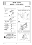
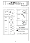
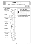
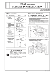
I. Accessory parts
[Video Interface Kit]
[Image Controller]
No.
No.
Name
Shape
Name
Shape
Q’ty
1. Relay circuit
board
Q’ty
1. Image
controller
1
9J05IXC005DA
2. Metal Blanking
Plate A
1
2
9J05IXC004DA
4037IXC018HC
3. Metal Blanking
Plate B
2. Power cord
1
4037IXC019HA
9J05IXC006DA
3. LAN cable
4. Shoulder
Screw
1
1
9J05IXC030DA
5. Screw A
(4 × 8 mm)
4037IXC020HA
4. Image
transmission
cable
1
4
9J05IXC032DA
6. Screw B
(3 × 6 mm)
1
5
9J05IXC032DA
7. Screw C
(4 × 8 mm)
4037IXC021HA
5. Mounting
screws
for the relay
circuit board
connector
6. Other*
2
9J05IXC033DA
2
8. Image
Controller
IC-406 User’s
Guide (Network
Scanner
Operations/
Copier Network
Functions)
9J05IXC031DA
–
* Since this is not directly related to the installation
of the interface kit, it is omitted here.
1
4037IXC027HA
9. Installation
Manual
1
set
4980IXC019DA
Note:
When banner printing function is used, optional
Expanded Memory Unit EM-309 is needed.
E-1
9J05-9554-00
III. Installation procedures
Note:
To install this Kit, the Paper Feed Cabinet or the
Desk must first be installed on the machine.
After unpacking, be sure to get rid of the
packaging materials and keep them out of
the reach of children.
1. Turn off the machine.
2. Remove the cord clamp and unplug the power
cord from the machine (one screw).
Putting the head in the plastic bag
involves danger of suffocation.
II. Part Names
Ethernet 10Base-T/100Base-TX/1000Base-T
network port
USB port
Power cord
connector
4038IXC111DA
3. Remove the lower rear cover (seven screws).
LAN COPIER
Power switch
Softswitch LED
LAN cable port
Image transmission
connector
4037IXC002HD
Switches
<Power switch>
• When turned on, power starts to be supplied to
the image controller, and the image controller
system starts up.
• When turned off, the power supply to the image
controller is completely stopped. Before turning
off the power switch, make sure that the image
controller system is completely shut down.
9J06IXC034DA
4. Take out the Dust Filter of the backside of the
machine.
<Softswitch>
• When turned on, the image controller system
starts up.
• When turned off, the image controller system
safely shuts down.
4038IXC116DA
E-2
10. Remove the Metal Blanking Plate (one screw).
(Removed Metal Blanking Plate will be no more
necessary.)
5. Remove the upper rear cover (four screws).
4038IXC037DB
6. Disconnect the IR connector on the right side of
the machine.
7. Open the right door and then remove the right
rear cover (three screws).
9J05IXE012DA
11. Mount the shoulder screws to the position
shown on the illustration (one shoulder screw
furnished with the Video Interface Kit).
9J06IXC035DA
9J05IXE007DA
8. If the FAX Kit and the Local Interface Kit are
mounted to the machine, remove the FAX Kit and
the Local Interface Kit.
Note:
For the FAX Kit or the Local Interface Kit removal
procedure, see Installation Manual for them.
12. Mount the Relay circuit board.
(1) Set the connecter (PJ02) for the Relay circuit
board to the Metal Blanking Plate on the side.
(2) Connect the connector (PJ01) for the Relay circuit board with the connector (PJ04) for MFP
control board (PWB-MFPC).
9. Remove the shield cover (fifteen screws).
PJ02
PJ01
9J05IXE008DA
9J06IXC147DA
E-3
15. Reinstall the right rear cover that has been
removed in step 7 (three screws).
16. Plug in the IR connector that has been removed
in step 6 and close the right door.
(3) Secure the connector for the relay circuit board
with the mounting screw for the relay circuit
board connector.
9J05IXE014DA
9J05IXC017DB
(4) Secure the relay circuit board (one screw B furnished with the Video Interface Kit).
17. Reinstall the upper rear cover that has been
removed in step 5 (four screws).
9J05IXE016DA
4038IXC047DB
13. Reinstall the shield cover that has been removed
in step 9 (fifteen screws).
Note:
For three types of screw are used, refer the illustration to make sure the position of each screw.
18. Insert the Dust Filter that has been pull out in
step 4.
4038IXC117DA
9J06IXC148DA
14. Mount the FAX Kit and the Local Interface Kit
that have been removed in step 8.
Note:
For the FAX Kit or the Local Interface Kit mounting
procedure, see Installation Manual for them.
E-4
22. Attach the image controller to the back of the
machine, and then slide the controller to the
right.
Note:
During installation, be careful that the image controller is not dropped.
19. Reinstall the lower rear cover that has been
removed in step 3 (seven screws).
9J05IXC018DA
20. Unhook two tab, and remove the wiring cover.
9J05IXC001DB
23. Secure the image controller (four screw A’s furnished with the Video Interface Kit).
9J05IXC019DA
21. Install the Metal Blanking A and B (two screw B’s
for each side and two screw C’s furnished with
the Video Interface Kit).
9J05IXE023DA
24. Connect the machine and the Image Controller
using the Image transmission cable furnished
with the Image Controller.
Screw B
Screw C
9J05IXE021DA
9J05IXE025DB
E-5
IV. Connecting the Power Cords
25. Connect the machine and the Image Controller
using the LAN cable furnished with the Image
Controller.
Note:
Use the furnished power cable without fail.
1. Connect the power outlet for the outer controller
of the machine and the connector for the power
cable on the Image controller using the power
cable furnished with the Image controller.
9J05IXE028DA
2. Plug the power cord into the machine and put the
cord clamp that has been removed in P. E-3 step
2 through the power cord to install it (one screw).
9J05IXE027DB
9J05IXE029DA
E-6
V. Specifying the Machine Settings
8. Turn the machine off, then on again. (If the
machine has not been turned off, the setting
changes are not applied.)
From the machine, specify the necessary settings
for using the controller.
The precautions for changing “Controller 1” on the
machine to any setting other than “Controller 1”
and for returning the setting to “Controller 1” are
provided at the end of this manual.
<Image Controller Setting>
1. Turn on the machine.
2. Display the Service Mode screen.
(For details of how to display the Service Mode
screen, see the Service Manual.)
3. Touch “System 2.”
VI. Specifying the Controller Settings
Specify the default settings for the controller.
1. Turn on the controller.
2. Turn on the machine.
Procedures for turning the Controller and the
Machine ON/OFF are described at the end of this
manual.
3. Wait until “Language Setup” is displayed at the
lower-left corner of the screen in the machine’s
touch panel.
4. Press the [Utility/Counter] key on the machine.
5. Touch “Controller Details.”
Note:
If “Controller Details” does not appear, wait a short
while, and then repeat steps 3 and 4.
4037IXE295DA
4. Touch “Image Controller Setting.”
6. In the Language Setup screen, select the language and market region.
After the settings have been specified, the controller restarts.
7. When the password is entered, the Setup screen
appears. The default password is “Fiery.1.” (Be
sure to type in the password with the correct capitalization.)
8. The Setup screen appears in the controller operation panel.
9. Touch “Server Setup.”
10. Without specifying any other settings, touch
“Exit.” When “Save Changes” appears, select
“Yes.”
11. In the same way, select “Network Setup”, “Protocol Setup”, “IPv4 Setup”, then “Ethernet Setup”,
and then set “Enable IPv4 for Ethernet” to “Yes”
and “Enable Auto IP Configuration” to “No.”
12. Specify settings for the following.
4061IXE159DB
5. Touch “Controller 1.”
IP Address:
Controller IP address
Subnet Mask: Subnet mask for the connected
network
Gateway
Address:
4037IXE033HB
6. Touch “END.”
7. Touch “Exit.”
IP address of the default
gateway
Note:
First check with your network administrator for the
settings that should be entered.
13. Touch “Menu” three times, and then select “Yes”
when “Save Changes” appears.
14. Touch “Print Setup.”
E-7
IX. Installing the Patch Files
15. Touch “Menu.” When “Save Changes” appears,
press the button to the right of “OK.”
16. When “Exit Setup” appears, select it to reboot
the image controller.
17. After the image controller is ready to be used,
turn the machine off, then on again.
<Objective>
• The image controller is recognized as a KONICA
MINOLTA product when a network management
tool (for example, PageScope Net Care) is used.
• The KONICA MINOLTA logo appears at the top of
the PageScope Web Connection page.
Note:
This patch file is not provided on the CD-ROM
supplied with the image controller; it must be
acquired separately.
VII. Checking the Setup With a Test Print
After setting up the controller, print the configuration
page to check that the controller is operating correctly.
<To install the patch file>
1. Check that the computer can communicate with
the controller through the TCP/IP protocol.
2. Install Command Work Station (from the CDROM included with the image controller) onto the
computer.
3. Start up Command Work Station.
4. Select the controller from the “Available Servers”
list, and then click “Add.”
5. Log on with administrator permissions. The
default password is “Fiery.1.” (Be sure to type in
the password with the correct capitalization.)
6. From the File menu, point to “Import”, and then
click “Job.”
7. In the Select File to Import dialog box, select the
patch file, and then click [Add].
8. In the “Logical Printer” box, select “30C-KM
direct”, and then click “Import.”
9. In order to apply the patch file settings, the image
controller must be restarted. Wait at least 60 seconds before restarting the image controller.
10. Follow the procedure described below to access
PageScope Web Connection and check that the
KONICA MINOLTA logo appears on the page.
<To print a test page>
1. Press the [Utility/Counter] key on the machine.
2. Touch “Controller Details.”
3. Touch “Menu.”
4. Select “Print Pages.”
The names of the pages that can be printed are
displayed.
5. Select “Configuration.”
VIII. Connecting to a computer
Use a network cable (Category 5E or over recommended) to connect the image controller to the computer.
Port 1
LED1
LED2
LED1
LED2
Port 2
<To access PageScope Web Connection>
In the Address bar of a Web browser, type the IP
address of the controller, and then press the [Enter]
key.
Example: http://192.168.0.200/
The following PageScope Web Connection page
appears.
Softswitch LED
9J05IXC034DB
LED descriptions
Port 1 (For the LAN)
LED1:
Lights up in green when linked at 1 Gb
Lights up in red when linked at 100 Mb
LED2:
Lights up in orange when linked at 10 Mb
Port 2 (For the MACHINE)
LED1:
Lights up in red when linked at 100 Mb
LED2:
Lights up in orange when communicating
with the machine
Softswitch
Lights up when the image controller is running or
is ready to be used
9J05IXE035DA
E-8
X. Reference Information
Turning power ON/OFF
The following procedures describe how to turn ON/
OFF the Image Controller and the Machine.
Precautions for changing “Controller 1” on the
machine to any setting other than “Controller 1”
and for returning the setting to “Controller 1”
Since the following settings are initialized when a
setting other than “Controller 1” is selected, even if
the following settings were specified when “Controller 1” was selected, the following settings may need
to be reset if “Controller 1” is selected again and IC406 is used.
<To turn on the unit when the power switch and softswitch are off>
1. Turn on the power switch on the image controller.
2. Check that the image controller is ready to be
used, and then turn on the machine.
<To turn on the system when the power switch is on,
but the softswitch indicator is off>
1. Turn on the softswitch on the image controller.
2. Check that the image controller is ready to be
used, and then turn on the machine.
Machine control panel
• “Administrator Setting” – “Network Setting”
NetWare Setting
SMB Setting
FTP Setting
E-Mail Setting
LDAP Setting
TCP Socket Setting
Time Adjustment Setting
Device Setting
• “Administrator Setting” – “User Authentication/
Account Track”
Authentication Method – ON (External Server)
• “Administrator Setting” – “System Connection”
OpenAPI Setting
Turning power for the machine ON too soon may
cause trouble. Refer to the following for detail.
<To turn off the system>
1. Use either the control panel or the softswitch to
shut down the image controller.
2. Check that the image controller is shut down, and
then turn off the power switch of the image controller.
3. Turn off the machine.
Timing for turning on the machine
The machine and image controller communicate
internally through a cross cable. If the DHCP function is enabled on the image controller, the network
interface card in the machine performs a DHCP
request when it is turned on in order to acquire the
IP address necessary for communicating with the
image controller as well as DNS setting used for the
network function on the machine. Since a DHCP
request is performed when the machine is turned
on, the IP address cannot be acquired if the
machine is turned on before the image controller is
ready to be used, preventing communications with
the image controller.
Scanning
• Mailbox Destination
• Information on the original specified by the Program Destination
• “User Setting” – “Initial Setting” – Scan
E-9