1
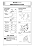
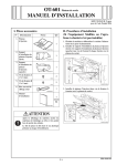
10. Remove the Metal Blanking Plate (one screw).
(Removed Metal Blanking Plate will be no more
necessary.)
5. Remove the upper rear cover (four screws).
4038IXC037DB
6. Disconnect the IR connector on the right side of
the machine.
7. Open the right door and then remove the right
rear cover (three screws).
9J05IXE012DA
11. Mount the shoulder screws to the position
shown on the illustration (one shoulder screw
furnished with the Video Interface Kit).
9J06IXC035DA
9J05IXE007DA
8. If the FAX Kit and the Local Interface Kit are
mounted to the machine, remove the FAX Kit and
the Local Interface Kit.
Note:
For the FAX Kit or the Local Interface Kit removal
procedure, see Installation Manual for them.
12. Mount the Relay circuit board.
(1) Set the connecter (PJ02) for the Relay circuit
board to the Metal Blanking Plate on the side.
(2) Connect the connector (PJ01) for the Relay circuit board with the connector (PJ04) for MFP
control board (PWB-MFPC).
9. Remove the shield cover (fifteen screws).
PJ02
PJ01
9J05IXE008DA
9J06IXC147DA
E-3