1
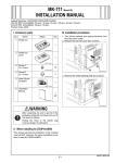
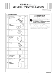
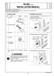
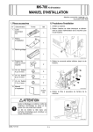
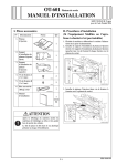
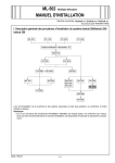
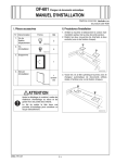
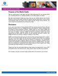
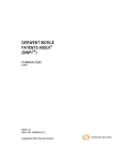
SA-501 Scan Accelerator Kit
INSTALLATION MANUAL
Applied Machines: C353/C253/C203
COLOR MFP (Color/B&W): 35 ppm/35 ppm, 25 ppm/25 ppm, 20 ppm/20 ppm
Product Code: A02E
I. Accessory parts
No.
Name
II. Installation procedures
Shape
<When the machine is already equipped with MK711>
1. Turn off the machine and unplug the power cord
from the power outlet.
2. Remove the shield box cover (four screws).
Q’ty
1. JPEG board
1
4037IXC053DA
2. Screw
(3 × 8 mm)
2
4037IXC151DA
3. Installation
manual
1 set
A0DCIXC007DA
4980IXC019DA
3. Pull out the filter from the rear right of the
machine.
After unpacking, be sure to get rid of the
packaging materials and keep them out of
the reach of children.
Putting the head in the plastic bag
involves danger of suffocation.
A0DPIXC001DA
E-1
A02E-9962-00
4. Open the right door.
5. Open the right rear door.
6. Remove the right rear cover (five screws).
9. Insert the JPEG board assy into the machine and
secure it by tightening the shoulder screws (two
shoulder screws).
Note:
When inserting the board, align it with the slits in
the machine.
A0DPIXC002DB
7. Loosen the two shoulder screws and remove the
shield cover (two shoulder screws).
A02EIXC074DB
10. Reinstall the right rear cover that has been
removed in step 6 (five screws).
11. Close the right rear door.
12. Close the right door.
13. Insert the filter that has been pull out in step 3.
14. Reinstall the shield box cover that has been
removed in step 2 (four screws).
A02EIXC073DA
8. Install the shield cover that has been removed in
step 7 to the JPEG board (two screws furnished
with the kit).
4037IXC056DB
E-2
III. Scan accelerator setting
<When both the fax kit and MK-711 are installed at
one time>
1. Turn off the machine and unplug the power cord
from the power outlet.
2. Loosen the two shoulder screws and remove the
shield cover (two shoulder screws).
1. Plug the power cord into the power outlet and
turn on the machine.
2. Display the Service Mode screen (For details of
how to display the Service Mode screen, see the
service manual).
3. Touch “System 2.”
A02EIXC075DB
A00JIXE118DA
3. Install the shield cover that has been removed in
step 2 to the JPEG board (two screws furnished
with the kit).
4. Touch “Option Board Status.”
A02EIXE062DA
4037IXC056DB
5. Touch “Set” of JPEG.
4. Insert the JPEG board assy into the machine and
secure it by tightening the shoulder screws (two
shoulder screws).
Note:
When inserting the board, align it with the slits in
the machine.
A00JIXE133DA
6. Touch “END.”
7. Touch “Exit” on the Service Mode screen.
8. Turn OFF and ON the Main Power Switch.
Note:
When displayed the Service Mode screen, be sure
to turn off the main power after exiting the Service
Mode screen and wait for 10 seconds or more
before turning on.
A02EIXC076DB
5. Mount the MK-711 (mount kit) to the machine.
Note:
For installation procedures, refer to the installation
manual for MK-711 (mount kit).
E-3