1
Real-Time Spectrum Analyzers
RSA6100A Series 6.2 GHz and 14 GHz Real-Time Spectrum Analyzers
Features & Benefits
Discover
– DPX® Spectrum Processing
Provides an Intuitive Understanding of Time-varying RF
Signals with Color Graded
Displays Based on Frequency
of Occurrence
– Revolutionary DPX Displays
Transients as Short as 24 µs with
100% Probability of Intercept
Trigger
– Tektronix Exclusive 40 MHz
and 110 MHz Frequency Mask
Triggers (FMT) Offer Easy Eventbased Capture of Transient RF
Signals by Triggering on Any
Change in the Frequency Domain
Completely Characterize Time-Varying RF Signals
The RSA6100A Series will help you to
easily discover design issues that other
signal analyzers may miss. The revolutionary DPX spectrum display offers an
intuitive live color view of signal transients
changing over time in the frequency
domain, giving you immediate confidence
in the stability of your design or instantly
displaying a fault when it occurs. This
live display of transients is impossible with
other signal analyzers. Once a problem
is discovered with DPX, the RSA6100A
Series of Real-Time Spectrum Analyzers
(RTSA) can be set to trigger on the event,
capture a continuous time record of
changing RF events and perform timecorrelated analysis in all domains. You
get the functionality of a wide-band vector
signal analyzer, a spectrum analyzer
and the unique trigger-capture-analyze
capability of a Real-Time Spectrum
Analyzer – all in a single package.
Capture
– All Signals in Up to 110 MHz
Spans are Captured into Memory
– Up to 1.7 s Acquisition Length at
110 MHz Bandwidth Provides
Complete Analysis Over Time
Without Making Multiple
Acquisitions
– 6.2 GHz and 14 GHz Models
Available
Analyze
– Extensive Time-correlated Multidomain Displays Connect
Problems in Time, Frequency,
Phase and Amplitude for Quicker
Understanding of Cause and
Effect when Troubleshooting
– Power Measurements and
Signal Statistics Help You
Characterize Components and
Systems: ACLR, Multi-Carrier
ACLR, Power vs. Time, CCDF
– Advanced Measurement Suite
(Opt. 20) – Pulse Measurements
Including Rise Time, Pulse
Width and Pulse-to-Pulse Phase
Provide Deep Insight into Pulse
Train Behavior
– General Purpose Digital
Modulation Analysis (Opt. 21)
Provides Vector Signal
Analyzer Functionality
– Tektronix OpenChoice® Makes
for Easy Transfer to a Variety
of Analysis Programs
Applications
– Characterize Radar and Pulsed
RF Signals
– Capture Vector Signal Parameters
of Multi-Carrier 3G and 4G
Systems for Offline Analysis
– Analyze Time Variant Behavior of
Cognitive Radio and Software
Defined Radio Systems
– Find Interference and Unknown
Signals in Spectrum Monitoring
and Management
– Troubleshoot RF Components,
Modules or Systems
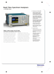
Revolutionary DPX™ spectrum display reveals transient signal behavior that helps you discover
instability, glitches and interference. Here, an infrequently occurring transient is seen in detail.
The frequency of occurrence is color-graded, indicating the infrequent transient event in blue
and the noise background in red.
Real-Time Spectrum Analyzers
RSA6100A Series 6.2 GHz and 14 GHz Real-Time Spectrum Analyzers
Discover
The patented DPX® spectrum processing
engine brings live analysis of transient
events to spectrum analyzers. Performing
>48,000 frequency transforms per second,
transients as brief as 24 µs in length are
displayed in the frequency domain. This
is a 1000-fold improvement over swept
analysis techniques. Events can be color
coded by rate of occurrence onto a bitmapped display, providing unparalleled
insight into transient signal behavior.
Trigger
The patented Tektronix Frequency Mask
Trigger (FMT) Opt. 02 makes it easy to
capture transient signals in up to a
110 MHz bandwidth. An FMT is simply
configured to monitor all changes in
frequency occupancy within the capture
bandwidth. A Power Trigger, working in
the time domain and in any capture
bandwidth, can be armed to monitor for
a user-set power threshold to be crossed
during a moment in time. Resolution
bandwidths may be used with the power
trigger for band-limiting and noise reduction. Two external triggers are available
for synchronization to test system events.
Capture
Capture once – make multiple measurements without recapturing. All signals in a
capture bandwidth are recorded into the
RSA6100A Series deep memory. Record
lengths vary depending upon the selected
capture bandwidth-up to 1.7 seconds
at 110 MHz, 102 seconds at 1 MHz or
2.1 hours at 10 kHz bandwidth with
2
Trigger and Capture: The frequency mask trigger monitors for changes in the frequency domain
and captures any violations into memory. The spectrogram display (left panel) shows frequency and
amplitude changing over time. By selecting the point in time in the spectrogram where the spectrum
violation triggered the FMT, the frequency domain view (right panel) automatically updates to show
the detailed spectrum view at that precise moment in time.
FMT/Deep Memory Option 02. Realtime capture of small signals in the
presence of large signals is enabled
with 73 dB SFDR in all capture bandwidths, even up to 110 MHz (Opt. 110).
Analyze
The RSA6100A Series introduces analysis
capabilities that advance productivity for
engineers working on components or in
RF system design, integration and
performance verification, or operations
engineers working in networks or spectrum management. Spectrograms display
both frequency and amplitude changes
over time. Time-correlated measurements
can be made across the frequency,
Real-Time Spectrum Analyzers • www.tektronix.com/rsa
phase, amplitude and modulation
domains. This is ideal for signal analysis
that includes frequency hopping, pulse
characteristics, modulation switching,
settling time, bandwidth changes and
intermittent signals.
The Windows XP environment makes
this multi-domain analysis even easier
with an unlimited number of analysis
windows, all time-correlated, to provide
deeper insight into signal behavior. A user
interface that adapts to your preferences
(keyboard, front-panel, touch-screen and
mouse) makes learning the RSA6100A
Series easy for both first-time users
and experienced hands.
Real-Time Spectrum Analyzers
RSA6100A Series 6.2 GHz and 14 GHz Real-Time Spectrum Analyzers
Options Tailor Your RSA for Specific Applications
The RSA6100A Series offers options to meet your specific application, whether it be radar characterization, communications system
design, cognitive or software-defined radio research or spectrum management.
Example Applications Benefiting from Key RSA61000A Series Standard Capabilities and Options
Analysis Feature
SDR and Cognitive
Radio
Cellular, WLAN,
General Comms
Radar, Pulsed
Signals
Spectrum
Management
DPX® Spectrum Processing
X
X
X
X
Frequency Mask Trigger
(Opt. 02)
X
X
X
X
110 MHz Capture Bandwidth
(Opt. 110)
X
X
X
X
Spectrogram
X
X
X
X
Multi-domain Correlation
X
X
X
X
Internal Preamplifier (Opt. 01)
X
X
X
X
Digital IQ and Analog IF Output
(Opt. 05)
X
X
X
X
X
X
X
X
X
X
Removable HDD (Opt. 06)
General Purpose Digital
Modulation Analysis (Opt. 21)
X
X
Advanced (Pulsed) Signal
Analysis (Opt. 20)
Time-correlated, multi-domain view provides a new level of insight into
design or operational problems not possible with conventional analysis
solutions. Here, ACLR and Vector Modulation Quality (Opt. 21) are performed
on a single acquisition, combined with the continuous monitoring of the
DPX spectrum display.
Pulse measurements, available in the Advanced Signal Analysis package
(Opt. 20): A pulse train (upper left) is seen with measurements of peak
power, pulse width, rise time and pulse-to-pulse phase (upper right). A
detailed view of the pulse rise time is seen in the lower left, and a DPX
display monitors the spectrum on the lower right.
Real-Time Spectrum Analyzers • www.tektronix.com/rsa
3
Real-Time Spectrum Analyzers
RSA6100A Series 6.2 GHz and 14 GHz Real-Time Spectrum Analyzers
Characteristics
Trigger-related
Acquisition Mode –
Single or Continuous, Free Run or Triggered.
Trigger Event Source –
Trigger 1 (front), Trigger 2/Gate (rear), Line.
Trigger Types – Level or Frequency Mask.
Trigger Setting –
Trigger position settable from 0 to 100% of total
acquisition length.
Trigger Combinational Logic –
Trig 1 AND Trig 2/Gate may be defined
as a trigger event.
Trigger Delay –
Frequency Mask Trigger
(Opt. 02)
Mask Shape – User-defined.
Mask Point Horizontal Resolution – <0.2% of span.
Level Range – 0 dB to –80 dB from reference level.
Level Accuracy*1 –
0 to –50 dB from reference level: ±(IF Frequency
Response + 1.0 dB).
–50 dB to –70 dB from reference level: ±(IF
Frequency Response + 2.5 dB).
Span Range –
100 Hz to 40 MHz (Opt. 02).
100 Hz to 110 MHz (Opt. 02 + Opt. 110).
Minimum Event Duration for 100% Probability
of Trigger – (At maximum acquisition bandwidth.)
30.7 µSec (10.3 µSec, Opt. 02 + Opt. 110).
Events lasting less than minimum event duration
specification will result in degraded Frequency Mask
Trigger accuracy.
Range: 20 ns to 60 s.
Resolution: 20 ns.
Uncertainty: ±20 ns.
Power Level Trigger
Level Range –
0 dB to –100 dB from reference level.
Accuracy –
(For trigger levels >30 dB above noise floor,
10% to 90% of signal level.)
±0.5 dB ( level ≥–50 dB from reference level).
±1.5 dB (from <–50 dB to –70 dB from
reference level).
Trigger Position Uncertainty –
Span = 40 MHz: ±12.8 µs.
Span = 110 MHz: ±5.12 µs (Opt. 02 + Opt. 110).
External Trigger 1
Level Range – –2.5 V to +2.5 V.
Level Setting Resolution – 0.01 V.
Trigger Position Timing Uncertainty (50 Ω input
impedance) –
40 MHz acquisition BW, 40 MHz Span: Uncertainty
= ±20 ns.
110 MHz acquisition BW, 110 MHz Span (Opt 110):
Uncertainty = ±12 ns.
Trigger Bandwidth Range –
(At maximum acquisition BW.)
4 kHz to 20 MHz + wide open (standard).
11 kHz to 60 MHz + wide open (Option 110).
Trigger Position Timing Uncertainty –
40 MHz Acquisition BW, 20 MHz BW:
Uncertainty = ±10 ns.
110 MHz Acquisition BW, 60 MHz BW (Opt. 110):
Uncertainty = ±3.3 ns.
4
Input Impedance –
Selectable 50 Ω/5 kΩ Impedance (nominal).
*1
For masks >30 dB above noise floor.
Real-Time Spectrum Analyzers • www.tektronix.com/rsa
External Trigger 2
Threshold Voltage – Fixed, TTL.
Input Impedance – 10 kΩ (nominal).
Trigger State Select – High, low.
Trigger Output
Voltage (Output Current <1 mA) –
High: >2.0 V; Low: <0.4 V (LVTTL).
Capture-related
Real-time Capture Bandwidth –
40 MHz (110 MHz, Opt. 110).
A/D Converter –
100 MS/s 14 bit (additional 300 MS/s,
12 bit, Opt. 110).
Acquisition Memory Size –
256 MB (1 GB, Opt. 02).
Minimum Acquisition Length – 2 Samples.
Acquisition Length Setting Resolution – 1 Sample.
Real-Time Spectrum Analyzers
RSA6100A Series 6.2 GHz and 14 GHz Real-Time Spectrum Analyzers
Memory Depth (Time) and Minimum Time Domain Resolution
Acquisition BW
Sample Rate
(For I and Q)
110 MHz (Opt. 110)
150 MS/s
60 MHz (Opt. 110)
75 MS/s
40 MHz
50 MS/s
20 MHz
25 MS/s
10 MHz
5 MHz
Acquisition Time
(Option 02)
Min Time
Resolution
0.426 s
1.706 s
6.6667 ns
0.852 s
3.413 s
13.33 ns
1.28 s
5.12 s
20 ns
2.56 s
10.2 s
40 ns
12.5 MS/s
5.12 s
20.5 s
80 ns
6.25 MS/s
10.2 s
41.0 s
160 ns
2 MHz*2
3.125 MS/s
10.2 s
41.0 s
320 ns
1 MHz
1.56 MS/s
20.5 s
81.9 s
640 ns
500 kHz
781 kS/s
41.0 s
164 s
1.28 µs
200 kHz
390 kS/s
81.9 s
328 s
2.56 µs
100 kHz
195 kS/s
164 s
655 s
5.12 µs
50 kHz
97.6 kS/s
328 s
1310 s
10.24 µs
20 kHz
48.8 kS/s
655 s
2620 s
20.48 µs
10 kHz
24.4 kS/s
1310 s
5240 s
40.96 µs
5 kHz
12.2 kS/s
2620 s
10500 s
81.92 µs
2 kHz
3.05 kS/s
10500 s
41900 s
328 µs
1 kHz
1.52 kS/s
21000 s
83900 s
655 µs
500 Hz
762 S/s
41900 s
168000 s
1.31 ms
200 Hz
381 S/s
83900 s
336000 s
2.62 ms
100 Hz
190 S/s
168300 s
671000 s
5.24 ms
*2
Acquisition Time
In spans ≤2MHz, higher resolution data is stored, reducing acquisition time.
Real-Time Spectrum Analyzers • www.tektronix.com/rsa
5
Real-Time Spectrum Analyzers
RSA6100A Series 6.2 GHz and 14 GHz Real-Time Spectrum Analyzers
Analysis-related
Measurement Functions
Power and Frequency Measurements
Measurements
Channel Power, Adjacent Channel Power, Multi Carrier Adjacent
Channel Power/Leakage Ratio, dBm/Hz Marker, dBc/Hz Marker
Time Domain and Statistical Measurements
RF I/Q vs. Time, Power vs. Time, Frequency vs. Time, Phase vs. Time,
CCDF, Peak-to-Average Ratio
Advanced Measurements Suite (Option 20)
Rise Time, Fall Time, Pulse Width, Pulse Peak Power, Average Power,
Ripple, Pulse Repetition Interval, Duty Cycle, Pulse-Pulse Phase
Frequency Error, Droop, Trend, FFT of Trend
General Purpose Digital Modulation Analysis (Option 21)
EVM (RMS, Peak, EVM vs. Time), Magnitude Error (RMS, Peak,
Mag Error vs. Time), Phase Error (RMS, Peak, Phase Error vs. Time),
Origin Offset, Frequency Error, Gain Imbalance, Quadrature Error,
Rho, Constellation, Symbol Table
Displays by Domain
Frequency
Time and Statistics
Advanced Measurements Suite (Option 20)
Digital Demod (Option 21)
6
Real-Time Spectrum Analyzers • www.tektronix.com/rsa
Views
Spectrum (Amplitude vs. Frequency)
DPX® Spectrum Display (Live RF Color-Graded Spectrum)
Spectrogram (Amplitude vs. Frequency over Time)
Frequency vs. Time
Amplitude vs. Time
Phase vs. Time
RF I&Q vs. Time
Time Overview
CCDF
Peak-to-Average-Ratio
Pulse Results Table
Pulse Trace (Selectable by Pulse Number)
Pulse Statistics (Trend of Pulse Results and FFT of Trend)
Constellation diagram
EVM vs. Time
Symbol Table (Binary or Hexadecimal)
Real-Time Spectrum Analyzers
RSA6100A Series 6.2 GHz and 14 GHz Real-Time Spectrum Analyzers
Spectrum Display Traces,
Detectors and Functions
Traces –
Three traces + 1 math waveform + 1 trace from
spectrogram for spectrum display.
Detector – Peak, –peak, average.
Trace Functions –
Normal, Average, Max Hold, Min Hold.
Spectrum Trace Length –
801, 2401, 4001, 8001 or 10401 points.
RF Performance
Frequency
Frequency Range –
9 kHz to 6.2/14 GHz (RSA6106A/RSA6114A).
Initial Center Frequency Setting Accuracy –
Within 10–7 after 10-minute warm-up.
Center Frequency Setting Resolution – 0.1 Hz.
Frequency Marker Readout Accuracy –
±(RE x MF + 0.001 x Span + 2) Hz.
RE: Reference Frequency Error.
MF: Marker Frequency (Hz).
Span Accuracy – ±0.3% (Auto mode).
Reference Frequency –
Initial Accuracy at Cal – 1 x 10⁻⁷ (after 10-minute
warm-up).
Aging per Day – 1 x 10⁻⁹ (after 30 days of operation).
Aging per 10 Years – 3 x 10⁻⁷ (after 10 years of
operation).
Temperature Drift – 2 x 10⁻⁸ (0 to 50 ºC).
Cumulative Error (Temperature + Aging) – 4 x 10⁻⁷
(within 10 years after calibration, typical).
Reference Output Level –
>0 dBm (internal reference selected).
Reference Output Level (loopthrough) –
0 dB nominal gain from Ext Ref In to Ref Output,
+15 dBm max. output.
External Reference Input Frequencies –
1 to 25 MHz (1 MHz steps) + 1.2288 MHz, 4.8 MHz
and 19.6608 MHz.
External Reference Input Frequency
Requirements –
Must be within ±3 x 10⁻⁷ of stated frequency input.
Spurious: <–80 dBc within 100 kHz offset.
Input Level Range: –10 dBm to +6 dBm.
Resolution Bandwidth
DPX® Digital Phosphor
Spectrum Processing
Spectrum Processing Rate – >48,828/s.
Trace Processing –
Color-graded bit map, +Peak, –Peak, Average.
Minimum Signal Duration for 100% Probability of
Detection (Max-hold On) – 31 µs (24 µs Opt. 110).
Span Range –
100 Hz to 40 MHz (110 MHz with Opt. 110).
Resolution BW Accuracy – 7%.
Resolution BW Range vs.
Span (DPX)
Resolution Bandwidth Range (Spectrum Analysis) –
1 Hz to 5 MHz (1, 2, 3, 5 sequence, auto-coupled)
or user-selected (arbitrary).
Resolution Bandwidth Shape –
1 Hz to 5 MHz – Approximately Gaussian, shape
factor 4.1:1 (60:3 dB) ±10%, typical.
Resolution Bandwidth Accuracy –
1 Hz to 5 MHz ±1% (Auto-coupled RBW Mode).
Span
RBW (Min)
110 MHz
600 kHz
55 MHz
300 kHz
40 MHz
200 kHz
20 MHz
100 kHz
10 MHz
50 kHz
Time Domain Bandwidth
5 MHz
25 kHz
Time Domain Bandwidth Range –
At least 1/10 to 1/10,000 of Acquisition Bandwidth,
1 Hz Minimum.
Time Domain BW Shape –
2 MHz
13 kHz
≤10 MHz, approximately Gaussian, shape factor
4.1:1(60:3 dB), ±10% typical.
20 MHz (60 MHz, Opt. 110), shape factor <2.5:1
(60:3 dB), typical.
Time Domain Bandwidth Accuracy –
1 Hz to 20 MHz, and (>20 MHz to 60 MHz Opt.
110), ±10%.
Minimum Settable Spectrum
Analysis RBW vs. Span
Frequency Span
>10 MHz
>1 MHz to 10 MHz
≤1 MHz
RBW
100 Hz
10 Hz
1 Hz
1 MHz
7 kHz
500 kHz
4 kHz
200 kHz
2 kHz
100 kHz
800 Hz
50 kHz
400 Hz
20 kHz
200 Hz
10 kHz
100 Hz
5 kHz
50 Hz
2 kHz
13 Hz
1 kHz
7 Hz
500 Hz
4 Hz
200 Hz
2 Hz
100 Hz
1 Hz
Real-Time Spectrum Analyzers • www.tektronix.com/rsa
7
Real-Time Spectrum Analyzers
Real-Time Spectrum Analyzers
RSA6100A Series 6.2 GHz and 14 GHz Real-Time Spectrum Analyzers
RSA6100A Series 6.2 GHz and 14 GHz Real-Time Spectrum Analyzers
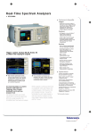
It’s Time to Get Real.
Completely Characterize
Time-varying RF Signals
Multiple correlated views
Two frequency ranges:
in all domains (Frequency, Time,
9 kHz to 6.2 GHz (RSA6106A) or
Amplitude, Phase, Modulation)
9 kHz to 14 GHz (RSA6114A).
with intuitive user interface.
Revolutionary DPX® spectrum
processing for unmatched
troubleshooting and live transient
DVD ±RW (standard) for waveform
analysis.
storage. Removable HDD (optional)
for data security.
Touch screen, mouse and front
panel controls directly adjust settings
in the views.
Familiar spectrum analyzer
controls plus fast access to all
Windows XP Operating System
acquisition and measurement
with Tek OpenChoice® for easy file
settings.
operations, printing, Ethernet and
GPIB control, remote connections
and more.
USB connections (2 front, 2 rear),
Two external triggers to capture
for mouse, keyboard and memory.
key event information (1 front, 1 rear).
DC-Protected Input
±40 V DC, over entire frequency
range, +30 dBm CW, 75W Pulse
Maximum.
8
Real-Time Spectrum Analyzers • www.tektronix.com/rsa
Real-Time Spectrum Analyzers • www.tektronix.com/rsa
9
Real-Time Spectrum Analyzers
RSA6100A Series 6.2 GHz and 14 GHz Real-Time Spectrum Analyzers
Phase Noise Sidebands, dBc/Hz at Specified Center Frequency (CF)
Offset
CF = 1 GHz
CF = 2 GHz
CF = 6 GHz
CF = 10 GHz
(RSA6114A)
Spec
Typical
Typical
Typical
Typical
100 Hz
–80
–86
–80
–70
–64
1 kHz
–100
–106
–106
–96
–91
10 kHz
–106
–110
–110
–107
–106
100 kHz
–107
–113
–111
–107
–106
1 MHz
–128
–134
–133
–132
–132
6 MHz
–134
–142
–142
–142
–142
10 MHz
–134
–142
–142
–142
–142
Stability
Residual FM –
<2 Hzpk-pk in 1 second (95% confidence, typical).
Amplitude
(Specifications excluding mismatch error.)
Measurement Range –
Displayed average noise level to maximum measurable input.
Input Attenuator Range – 0 dB to 75 dB, 5 dB step.
10
Maximum Safe Input Level –
Average Continuous (RF ATT ≥10 dB): +30 dBm.
Pulsed RF (RF ATT ≥30 dB, PW <10 µs, 1% Duty
Cycle): 75 W.
Maximum Measurable Input Level –
Average Continuous (RF ATT: Auto): +30 dBm.
Pulsed RF (RF ATT: Auto, PW <10 µs, 1% Duty
Cycle): 75 W.
MAX DC Voltage – ±40 V.
Log Display Range – 0.1 dB/div to 20 dB/div.
Display Divisions – 10 divisions.
Real-Time Spectrum Analyzers • www.tektronix.com/rsa
Display Units –
dBm, Volts, Watts, Hz for Frequency measurements,
Degrees for Phase measurements.
Marker Readout Resolution, dB Units – 0.01 dB.
Marker Readout Resolution, Volts Units –
Reference level dependent, as small as 0.001 µV.
Reference Level Setting Range –
0.1 dB step, –170 dBm to +50 dBm (minimum ref.
level –50 dBm at center frequency <80 MHz).
Level Linearity –
±0.1 dB (0 to –70 dB from Reference Level).
Real-Time Spectrum Analyzers
RSA6100A Series 6.2 GHz and 14 GHz Real-Time Spectrum Analyzers
Frequency Response
18 ºC to 28 ºC, Atten. = 10 dB, Preamp Off
10 MHz to 3 GHz
±0.5 dB
>3 GHz to 6.2 GHz
±0.8 dB
> 6.2 GHz to 14 GHz (RSA6114A)
±1.0 dB
5 ºC to 50 ºC, All Attenuator Settings (typical)
9 kHz to 3 GHz
±0.7 dB
>3 GHz to 6.2 GHz
±0.8 dB
>6.2 GHz to 14 GHz (RSA6114A)
±2.0 dB
Preamp (Opt. 01) ON (Att. = 10 dB)
10 MHz to 3 GHz
Absolute Amplitude Accuracy at Calibration
Point (100 MHz, –20 dBm signal, 10 dB ATT,
18 ºC to 28 ºC) – ±0.31 dB.
Input Attenuator Switching Uncertainty – ±0.2 dB.
±0.7 dB
VSWR –
(Att = 10 dB, Preamp OFF, CF set within 200 MHz
of VSWR test frequency.)
Absolute Amplitude Accuracy at Center
Frequency, 95% Confidence*3 (typical) –
10 MHz to 3 GHz: ±0.5 dB.
3 GHz to 6.2 GHz: ±0.8 dB.
6.2 GHz to 14 GHz: ±1.5 dB.
*3
10 MHz to 4 GHz: <1.6:1.
4 GHz to 6.2 GHz: <1.8:1.
6.2 GHz to 14 GHz (RSA6114A only): <1.9:1.
18 ºC to 28 ºC, Reference level ≤–15 dBm, Attenuator
Auto-coupled, signal level –15 dBm to –50 dBm. 10 Hz
≤RBW ≤1 MHz, after Alignment performed.
VSWR with Preamp –
(Att = 10 dB, Preamp ON, CF set within 200 MHz
of VSWR test frequency.
10 MHz to 3 GHz: <1.9:1.
Noise and Distortion
3rd Order Inter-modulation Distortion *4
Frequency
2.130 GHz
*4
3rd Order IM
<–80 dBc
3rd Order Intercept
3rd Order Intercept (typical)
+15 dBm
+17 dBm
Each signal level –25 dBm, Ref Level –20 dBm, Attenuator = 0 dB, 1 MHz tone separation.
3rd order intercept point is calculated from 3rd order intermodulation performance.
2nd Harmonic Distortion *5
Frequency
2nd Harmonic Distortion, Typical
10 MHz to 3.1 GHz
<–80 dBc
>3.1 GHz to 7 GHz (RSA6114 only)
<-80 dBc
*5
–40 dBm at RF input, Attenuator = 0, Preamp Off, typical.
Real-Time Spectrum Analyzers • www.tektronix.com/rsa
11
Real-Time Spectrum Analyzers
RSA6100A Series 6.2 GHz and 14 GHz Real-Time Spectrum Analyzers
Displayed Average Noise Level,*6 Preamp OFF
Frequency
Specification
Typical
9 kHz to 10 MHz
–97 dBm/Hz
–100 dBm/Hz
>10 MHz to 100 MHz
–147 dBm/Hz
–149 dBm/Hz
>100 MHz to 2.3 GHz
–149 dBm/Hz
–151 dBm/Hz
>2.3 GHz to 4 GHz
–147 dBm/Hz
–149 dBm/Hz
>4 GHz to 6.2 GHz
–143 dBm/Hz
–145 dBm/Hz
RSA6114A Only
4 GHz to 7 GHz
–143 dBm/Hz
–145 dBm/Hz
>7 GHz to 14 GHz
–135 dBm/Hz
–137 dBm/Hz
*6
Measured using 1 kHz RBW, 100 kHz Span, 100 Averages, Minimum Noise Mode, Input terminated.
Displayed Average Noise Level,*6 Preamp ON (Opt. 01)
Frequency
Specification
Typical
10 MHz to 80 MHz
–160 dBm/Hz
–170 dBm/Hz
>80 MHz to 1 GHz
–165 dBm/Hz
–170 dBm/Hz
1 GHz to 2 GHz
–166 dBm/Hz
–170 dBm/Hz
2 GHz to 3 GHz
–164 dBm/Hz
–170 dBm/Hz
Residual Response *7
Frequency
Spec
40 MHz to 200 MHz
–90 dBm
>200 MHz to 6.2 GHz
–95 dBm
>6.2 GHz to 14 GHz (RSA6114A)
*7
–95 dBm (typical)
Input Terminated, RBW = 1 kHz, Atten = 0 dB.
Image Response *8
Frequency
9 kHz to 6.2 GHz
Spec
<–80 dBc
6.2 GHz to 8 GHz (RSA6114A)
<–80 dBc
>8 GHz to 14 GHz (RSA6114A)
<–76 dBc
*8
Ref = –30 dBm, Atten = 10 dB, RF input Level = –30 dBm, RBW = 10 Hz.
12
Real-Time Spectrum Analyzers • www.tektronix.com/rsa
Real-Time Spectrum Analyzers
RSA6100A Series 6.2 GHz and 14 GHz Real-Time Spectrum Analyzers
Spurious Response with Signal *9
Frequency
Span ≤40 MHz,
swept spans >40 MHz
Option 110
40 MHz <span ≤110 MHz
Specification
Typical
Specification
Typical
10 MHz to 6.2 GHz
–73 dBc
–78 dBc
–73 dBc
–75 dBc
≥6.2 GHz to 14 GHz (RSA6114A)
–70 dBc
–75 dBc
–70 dBc
–75 dBc
*9
RF input level, –15 dBm, Atten = 10 dB, Offset ≥400 kHz, Mode: Auto.
Spurious Response with Signal at 4.75 GHz –
<–57 dBc (RF input level, –30 dBm).
Adjacent Channel Leakage Ratio Dynamic Range *10
Signal Type, Measurement Mode
ACLR, Typical
Adjacent
Alternate
3GPP Downlink, 1 DPCH
Uncorrected
Noise Corrected
–70 dB
–79 dB
–70 dB
–79 dB
3GPP TM1 64 channel
Uncorrected
Noise Corrected
–69 dB
–78 dB
–69 dB
–78 dB
*10 Measured with test signal amplitude adjusted for optimum performance. (CF = 2.13 GHz,)
IF Frequency Response and Phase Linearity *11
Frequency Range
Freq (GHz)
0.01 to
3.0*12
0.03 to 3.0
>3 to
6.2*12
Specification
Typical (RMS)
Acq. Bandwidth
Specification
Amplitude/Phase
≤300 kHz
±0.20 dB
0.05 dB/0.5º
≤40 MHz
±0.50 dB
0.18 dB/1.0º
0.05 dB/0.5º
≤300 kHz
±0.20 dB
>3 to 6.2
≤40 MHz
±0.50 dB
0.26 dB/1.0º
>6.2 to 14 (RSA6114A)
≤300 kHz
±0.20 dB
0.05 dB/1.0º
>6.2 to 14 (RSA6114A)
≤40 MHz
±0.80 dB
0.40 dB/1.0º
Option 110
0.07 to 3.0
≤80 MHz
±0.90 dB
0.40 dB/1.5º
0.07 to 3.0
≤110 MHz
±0.90 dB
0.40 dB/2.0º
>3 to 6.2
≤80 MHz
±0.90 dB
0.60 dB/1.5º
>3 to 6.2
≤110 MHz
±0.90 dB
0.60 dB/2.0º
>6.2 to 14 (RSA6114A)
≤80 MHz
±1.5 dB
0.70 dB/1.5º
>6.2 to 14 (RSA6114A)
≤110 MHz
±1.5 dB
1.0 dB/2.25º
*11
Amplitude flatness and phase deviation over the capture BW, includes RF frequency response. Attenuator setting: 10 dB.
*12
High Dynamic Range Mode selected.
Real-Time Spectrum Analyzers • www.tektronix.com/rsa
13
Real-Time Spectrum Analyzers
RSA6100A Series 6.2 GHz and 14 GHz Real-Time Spectrum Analyzers
Advanced Measurement Suite
(Opt. 20)
Measurements –
Rise Time, Fall Time, Pulse Width, Peak Power,
Average Power, Ripple, Pulse Repetition Interval,
Duty Cycle, Pulse-Pulse Phase, Frequency Error,
Droop, Trend, FFT of Trend.
Minimum Pulse Width for Detection –
150 ns (standard), 50 ns (Opt. 110).
System Rise Time (typical) –
<25 ns (standard), <10 ns (Opt. 110).
Pulse Measurement Accuracy –
Signal Conditions: Unless otherwise stated, Pulse
Width >450 ns (150 ns, Opt. 110), S/N Ratio ≥30
dB, Duty Cycle 0.5 to 0.001, temperature 18 ºC
to 28 ºC.
Measurement
Accuracy (typical)
Average ON Power*13
±0.3 dB + Absolute Amplitude Accuracy
Average Transmitted Power*13
±0.4 dB + Absolute Amplitude Accuracy
Peak Power*13
±0.4 dB + Absolute Amplitude Accuracy
Pulse Width
±3% of reading
Duty Factor
±3% of reading
Phase*14
Pulse-to-Pulse
At Stated
Frequency and Measurement Bandwidth
At 10 GHz
At 2 GHz
BW: 20 MHz
±1.7º
±3.2º
BW: 40 MHz
±1.7º
±3.7º
BW: 60 MHz (Opt. 110)
±1.9º
±4º
BW: 110 MHz (Opt. 110)
±2º
±5º
*13
Pulse width >300 ns (100 ns, Opt. 110).
*14
Pulse ON power ≥–20 dBm, signal peak at Reference Level, Attenuator = Auto, tmeas – treference ≤10 ms, Frequency Estimation: Manual, CW (non-chirped) pulses. Measurement time position excludes the beginning and ending of the pulse extending for a time = (10/Measurement BW) as measured from 50% of the t(rise) or t(fall).
Digital Modulation Analysis
(Option 21)
Modulation Formats –
BPSK, QPSK, 8PSK, 16QAM, 64QAM, 256QAM,
GMSK, π/4DQPSK DQPSK, D8PSK.
Analysis Period – Up to 80,000 Samples.
Filter Types –
Measurement Filters: Square root raised cosine, raised
cosine, Gaussian, rectangular, IS-95, IS-95 EQ, none.
Reference Filters: Raised cosine, Gaussian, rectangular, IS-95, none.
Alpha/B*T Range – 0.001 to 1, 0.001 step
Symbol Rate Range –
1 kSymbols/s to 100 MSymbols/s (Modulated signal
must be contained entirely within acquisition BW of
RSA6100A).
14
Demodulation Accuracy
256 QAM Residual EVM
(typical)*16
Digital (Option 21).
QPSK Residual EVM (typical)*15
Symbol Rate
Residual EVM
100 kSymbols/s
1 MSymbol/s
10 MSymbol/s
30 MSymbol/s
80 MSymbols/s (Opt. 110)
*15
<0.6%
<0.7%
<1.0%
<3.0%
<3.0%
CF = 2 GHz, Measurement Filter = root raised cosine, reference filter = raised cosine, analysis length = 200 symbols.
Real-Time Spectrum Analyzers • www.tektronix.com/rsa
Symbol Rate
Residual EVM
10 MSymbol/s
30 MSymbol/s
80 MSymbols/s (Opt. 110)
*16
<1.0%
<3.0%
<3.0%
CF = 2 GHz, Measurement Filter = root raised cosine, reference filter = raised cosine, analysis length = 400 symbols.
Real-Time Spectrum Analyzers
RSA6100A Series 6.2 GHz and 14 GHz Real-Time Spectrum Analyzers
Inputs And Outputs
Front Panel
RF Input Connector – N type, 50 Ω.
Trigger Out –
BNC, High >2.0 V, Low: <0.4 V, output current
1 mA (LVTTL).
Trigger In –
BNC, 50 Ω/5 KΩ impedance (nominal), ±5 V Max
Input, –2.5 V to +2.5 V trigger level.
USB Ports – 1 USB 2.0, 1 USB 1.1.
Audio – Speaker.
Rear Panel
Analog IF and Digital IQ Output (Opt. 05).
Analog IF Output (Opt. 05).
Frequency –
500 MHz (±1 MHz based on center frequency
selection).
Output Level –
0 to –10 dBm for peak signal level of –20 dBm
at RF mixer (typical).
Filter Control: Wide open (square top) or
60 MHz Gaussian.
Bandwidth (Wide Open): >150 MHz (typical).
Bandwidth (Gaussian): 60 MHz, Gaussian to –12 dB.
Digital IQ Output (Opt. 05)
Connector Type – MDR (3M) 50 pin x 2.
Data Output –
Data is corrected for amplitude and phase response
in real time.
I data: 16 bit LVDS; Q data: 16 bit LVDS.
Control Output –
Clock: LVDS, MAX 50 MHz (150 MHz, Opt. 110)
DV (Data Valid), MSW (Most Significant Word)
indicators, LVDS.
Control Input –
IQ data output enabled, connecting GND enables
output of IQ data.
Clock Rising Edge to Data Transition Time
(hold time) –
8.4 ns (typical, standard), 1.58 ns (typical, Opt. 110).
Data Transition to Clock Rising Edge
(setup time) –
8.2 ns (typical, standard), 1.54 ns (typical, Opt. 110).
10 MHz REF OUT – 50 Ω, BNC, >0 dBm.
External REF IN –
50 Ω, BNC, –10 dBm – +6 dBm, 1 MHz to 25 MHz
in 1 MHz steps, plus 1.2288 MHz, 4.8 MHz and
19.6608 MHz.
External REF IN Frequency Accuracy Required –
≤±0.3 ppm.
TRIG 2/Gate IN –
BNC, High: 1.6 to 5.0 V, Low: 0 to 0.5 V.
GPIB Interface – IEEE 488.2.
LAN Interface Ethernet – RJ45, 10/100/1000Base-T.
USB Ports – USB 2.0, two ports.
VGA Output – VGA compatible, 15 D-sub.
Audio out – 3.5 mm headphone jack.
Noise Source Drive –
BNC, +28 V, 140 mA (nominal).
General Characteristics
Temperature Range –
Operating: +5 ºC to +50 ºC. (+5 ºC to +40 ºC
when accessing DVD).
Storage: –20 ºC to +60 ºC.
Warm-up Time – 20 min.
Altitude –
Operating: Up to 3000 m (Approximately 10,000 ft.).
Non-operating: Up to 12,190 m (40,000 ft.).
Relative Humidity –
Vibration –
Operating: 0.22 GRMS, 5 Hz to 500 Hz (except when
accessing DVD and Opt. 06 Removable HDD).
Non-operating: 2.28 GRMS, 5 Hz to 500 Hz.
Shock –
Operating: 15 G, half-sine, 11 ms duration. (1 G max
when accessing DVD and Opt. 06 Removable HDD).
Non-operating: 30 G, half-sine, 11 ms duration.
Safety –
UL 61010-1:2004.
CSA C22.2 No.61010-1-04.
Electromagnetic Compatibility – Complies with –
EC Council EMC Directive 89/336/EEC, amended by
93/68/EEC.
EN61326, Class A.
AS/NZS CISPR 11, Class A (Australia).
Power Requirements –
90 VAC to 240 VAC, 50 Hz to 60 Hz.
90 VAC to 132 VAC, 400 Hz.
Power Consumption – 600 W max.
Data Storage –
Internal HDD, USB ports, DVD±RW (Opt. 07),
Removable HDD (Opt. 06).
Calibration Interval – One year.
Warranty – One year.
GPIB – SCPI-compatible, IEEE 488.2 compliant.
Physical Characteristics
Weight
With All Options
Dimensions
Height
Width
Depth
kg
26.4
mm
282
473
531
lb.
58
in.
11.1
18.6
20.9
Note: Physical Characteristics, with feet, without accessory pouch.
Operating and Non-operating: 90% RH at 30 ºC
(No condensation, Max. wet bulb, 29 ºC).
(80% RH max when accessing DVD.)
Real-Time Spectrum Analyzers • www.tektronix.com/rsa
15
Real-Time Spectrum Analyzers
Contact Tektronix:
ASEAN / Australasia (65) 6356 3900
RSA6100A Series 6.2 GHz and 14 GHz Real-Time Spectrum Analyzers
Austria +41 52 675 3777
Balkan, Israel, South Africa and other ISE Countries +41 52 675 3777
Belgium 07 81 60166
Ordering Information
RSA6106A
Real-Time Spectrum Analyzer, 9 kHz to 6.2 GHz.
RSA6114A
Real-Time Spectrum Analyzer, 9 kHz to 14 GHz.
Both Include: Quick Start Manual (Printed), User
manual, Programmer’s manual (on CD), power
cord, BNC-N adapter, USB keyboard, USB mouse,
pouch, front cover. Please specify power plug and
language options when ordering.
Options
Opt. 01 – Internal Preamp, 10 MHz to 3 GHz,
30 dB gain, 4 dB Noise Figure at 2 GHz, typical.
Opt. 02 – 1 GB Memory, Frequency Mask Trigger.
Opt. 05 – Digital IQ Output and 500 MHz Analog
IF output.
Opt. 06 – Removable HDD.
Opt. 07 – DVD-RW, required option, no-cost
(not compatible with Opt. 6).
Opt. 08 – Removable Solid State Hard Drive.
Opt. 20 – Advanced Signal Analysis (including
pulse measurements).
Opt. 21 – General Purpose Modulation Analysis.
Opt. 110 – 110 MHz Real-time Capture BW.
Opt. 1R – Rackmount.
Accessories
RSA61RHD – Additional Removable Hard Drive
for use with Opt. 06 (Windows XP and instrument
SW pre-installed).
065-0765-00 – Additional Removable Solid State
Hard Drive for use with Opt. 08 (Windows XP and
instrument SW pre-installed).
Transit Case – 016-1963-00.
Rackmount Retrofit – 016-1962-00.
Additional Quick Start Manual (paper) –
071-1909-xx.
Additional User Manual (CD) – 063-3930-xx.
Service Manual (paper) – 071-1914-xx.
International Power Plugs
Opt. A0 – North America power.
Opt. A1 – Universal EURO power
Opt. A2 – United Kingdom power.
Opt. A3 – Australia power.
Opt. A4 – 240 V, North America power.
Opt. A5 – Switzerland power.
Opt. A6 – Japan power.
Opt. A10 – China power.
Opt. A11 – India power.
Opt. A99 – No power cord or AC adapter.
Brazil & South America (11) 40669400
Canada 1 (800) 661-5625
Central East Europe, Ukraine and the Baltics +41 52 675 3777
Central Europe & Greece +41 52 675 3777
Denmark +45 80 88 1401
Finland +41 52 675 3777
France +33 (0) 1 69 86 81 81
Service
Opt. C3 – Calibration Service 3 years.
Opt. C5 – Calibration Service 5 years.
Opt. D1 – Calibration Data Report.
Opt. D3 – Calibration Data Report 3 years
(with Opt. C3).
Opt. D5 – Calibration Data Report 5 years
(with Opt. C5).
Opt. R3 – Repair Service 3 years.
Opt. R5 – Repair Service 5 years.
Opt. CA1 – Single calibration or coverage for
the designated calibration interval, whichever
comes first.
Germany +49 (221) 94 77 400
Hong Kong (852) 2585-6688
India (91) 80-22275577
Italy +39 (02) 25086 1
Japan 81 (3) 6714-3010
Luxembourg +44 (0) 1344 392400
Mexico, Central America & Caribbean 52 (55) 5424700
Middle East, Asia and North Africa +41 52 675 3777
The Netherlands 090 02 021797
Norway 800 16098
People’s Republic of China 86 (10) 6235 1230
Poland +41 52 675 3777
Portugal 80 08 12370
Upgrades
Republic of Korea 82 (2) 528-5299
RSA61UP
Russia & CIS +7 (495) 7484900
South Africa +27 11 254 8360
International Power Plugs
Opt. 01 – Internal Preamp, 10 MHz to 3 GHz, 30 dB
gain, 4 dB Noise Figure at 2 GHz, typical.
Opt. 02 – 1 GB Memory, Frequency Mask Trigger.
Opt. 05 – Digital IQ Output and 500 MHz Analog
IF Output.
Opt. 20 – Advanced Signal Analysis (Including
Pulse Measurements).
Opt. 21 – General Purpose Modulation Analysis.
Opt. 110 – 110 MHz Real-time Capture BW.
Opt. IF – Installation labor.
Opt. IFC – Installation labor plus calibration.
Languages
Opt. L0 – English Manual.
Opt. L5 – Japanese Manual.
Opt. L7 – Simplified Chinese Manual.
Opt. L10 – Russian Manual.
Spain (+34) 901 988 054
Sweden 020 08 80371
Switzerland +41 52 675 3777
Taiwan 886 (2) 2722-9622
United Kingdom & Eire +44 (0) 1344 392400
USA 1 (800) 426-2200
For other areas contact Tektronix, Inc. at: 1 (503) 627-7111
Updated 15 September 2006
Our most up-to-date product information is available at:
www.tektronix.com
Product(s) are manufactured in ISO registered facilities.
Product(s) complies with IEEE Standard 488.1-1987, RS-232-C, and with
Tektronix Standard Codes and Formats.
Copyright © 2006, Tektronix. All rights reserved. Tektronix products are covered
by U.S. and foreign patents, issued and pending. Information in this publication
supersedes that in all previously published material. Specification and price
change privileges reserved. TEKTRONIX and TEK are registered trademarks
of Tektronix, Inc. All other trade names referenced are the service marks,
trademarks or registered trademarks of their respective companies.
12/06
HB/WOW
37W-19513-1