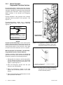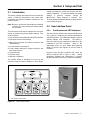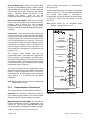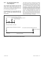
1
Operation and
Installation
Automatic Transfer Switches
Models:
KCT, KCP
Power Switching Device:
Standard
Open-Transition 30 to 4000 Amps
Programmed-Transition 150 to 4000 Amps
Electrical Controls:
MPAC 1000t
TP-6126 8/02b
Product Identification Information
Product identification numbers determine service parts.
Record the product identification numbers in the spaces
below immediately after unpacking the products so that
the numbers are readily available for future reference.
Record field-installed kit numbers after installing the
kits.
Transfer Switch Identification Numbers
Record the product identification numbers from the
transfer switch nameplate.
Model Designation
Serial Number
Accessory Number
Accessory Description
x:in:007:001
Table of Contents
Product Identification Information . . . . . . . . . . . . . . . . . . . . . . . . . . . . . . . . . . . . . . . . . . . . Inside front cover
Safety Precautions and Instructions . . . . . . . . . . . . . . . . . . . . . . . . . . . . . . . . . . . . . . . . . . . . . . . . . . . . . . . .
I
Introduction . . . . . . . . . . . . . . . . . . . . . . . . . . . . . . . . . . . . . . . . . . . . . . . . . . . . . . . . . . . . . . . . . . . . . . . . . . . . . . .
List of Related Materials . . . . . . . . . . . . . . . . . . . . . . . . . . . . . . . . . . . . . . . . . . . . . . . . . . . . .
i
i
Service Assistance . . . . . . . . . . . . . . . . . . . . . . . . . . . . . . . . . . . . . . . . . . . . . . . . . . . . . . . . . . . . . . . . . . . . . . . .
ii
Section 1 Product Description . . . . . . . . . . . . . . . . . . . . . . . . . . . . . . . . . . . . . . . . . . . . . . . . . . . . . . . . . . . . .
1.1 Purpose . . . . . . . . . . . . . . . . . . . . . . . . . . . . . . . . . . . . . . . . . . . . . . . . . . . . . . . . . . . . .
1.2 Nameplate . . . . . . . . . . . . . . . . . . . . . . . . . . . . . . . . . . . . . . . . . . . . . . . . . . . . . . . . . . .
1.3 Model Code . . . . . . . . . . . . . . . . . . . . . . . . . . . . . . . . . . . . . . . . . . . . . . . . . . . . . . . . . .
1
1
1
2
Section 2 Installation . . . . . . . . . . . . . . . . . . . . . . . . . . . . . . . . . . . . . . . . . . . . . . . . . . . . . . . . . . . . . . . . . . . . . .
2.1 Introduction . . . . . . . . . . . . . . . . . . . . . . . . . . . . . . . . . . . . . . . . . . . . . . . . . . . . . . . . . .
2.2 Receipt of Unit . . . . . . . . . . . . . . . . . . . . . . . . . . . . . . . . . . . . . . . . . . . . . . . . . . . . . . . .
2.2.1
Inspection . . . . . . . . . . . . . . . . . . . . . . . . . . . . . . . . . . . . . . . . . . . . . . . . . . . .
2.2.2
Lifting . . . . . . . . . . . . . . . . . . . . . . . . . . . . . . . . . . . . . . . . . . . . . . . . . . . . . . . .
2.2.3
Storage . . . . . . . . . . . . . . . . . . . . . . . . . . . . . . . . . . . . . . . . . . . . . . . . . . . . . .
2.2.4
Unpacking . . . . . . . . . . . . . . . . . . . . . . . . . . . . . . . . . . . . . . . . . . . . . . . . . . . .
2.3 Mechanical Installation . . . . . . . . . . . . . . . . . . . . . . . . . . . . . . . . . . . . . . . . . . . . . . . . .
2.4 Manual Operation Check . . . . . . . . . . . . . . . . . . . . . . . . . . . . . . . . . . . . . . . . . . . . . . .
2.4.1
Manual Operation, 30--200 Amp Open-Transition Switches . . . . . . . . . .
2.4.2
Manual Operation, 225--4000 Amp Open-Transition Switches . . . . . . .
2.4.3
Manual Operation, Programmed-Transition Switches . . . . . . . . . . . . . . .
2.5 Electrical Wiring . . . . . . . . . . . . . . . . . . . . . . . . . . . . . . . . . . . . . . . . . . . . . . . . . . . . . . .
2.5.1
AC Power Connections . . . . . . . . . . . . . . . . . . . . . . . . . . . . . . . . . . . . . . . .
2.5.2
Engine Start Connection . . . . . . . . . . . . . . . . . . . . . . . . . . . . . . . . . . . . . . .
2.5.3
Auxiliary Contacts . . . . . . . . . . . . . . . . . . . . . . . . . . . . . . . . . . . . . . . . . . . . .
2.5.4
Controller Ground . . . . . . . . . . . . . . . . . . . . . . . . . . . . . . . . . . . . . . . . . . . . .
3
3
3
3
3
4
4
4
5
5
6
8
9
10
13
15
16
Section 3 Setup and Test . . . . . . . . . . . . . . . . . . . . . . . . . . . . . . . . . . . . . . . . . . . . . . . . . . . . . . . . . . . . . . . . . .
3.1 Introduction . . . . . . . . . . . . . . . . . . . . . . . . . . . . . . . . . . . . . . . . . . . . . . . . . . . . . . . . . .
3.2 User Interface Panel . . . . . . . . . . . . . . . . . . . . . . . . . . . . . . . . . . . . . . . . . . . . . . . . . . .
3.2.1
Pushbuttons and LED Indicators . . . . . . . . . . . . . . . . . . . . . . . . . . . . . . . .
3.2.2
Controller Reset . . . . . . . . . . . . . . . . . . . . . . . . . . . . . . . . . . . . . . . . . . . . . . .
3.3 Controller Main Logic Board . . . . . . . . . . . . . . . . . . . . . . . . . . . . . . . . . . . . . . . . . . . .
3.3.1
Main Logic Board DIP Switch Settings . . . . . . . . . . . . . . . . . . . . . . . . . . .
3.3.2
Main Logic Board Inputs and Outputs . . . . . . . . . . . . . . . . . . . . . . . . . . . .
3.3.3
Communications Connections . . . . . . . . . . . . . . . . . . . . . . . . . . . . . . . . . . .
3.4 Programmed-Transition Interface Board (PTIB) . . . . . . . . . . . . . . . . . . . . . . . . . . . .
3.5 System Settings and Time Delays . . . . . . . . . . . . . . . . . . . . . . . . . . . . . . . . . . . . . . .
3.5.1
System Parameters . . . . . . . . . . . . . . . . . . . . . . . . . . . . . . . . . . . . . . . . . . . .
3.5.2
Time Delays . . . . . . . . . . . . . . . . . . . . . . . . . . . . . . . . . . . . . . . . . . . . . . . . . .
3.6 Generator Set Preparation . . . . . . . . . . . . . . . . . . . . . . . . . . . . . . . . . . . . . . . . . . . . . .
3.7 Functional Test . . . . . . . . . . . . . . . . . . . . . . . . . . . . . . . . . . . . . . . . . . . . . . . . . . . . . . .
3.7.1
Manual Operation Test . . . . . . . . . . . . . . . . . . . . . . . . . . . . . . . . . . . . . . . . .
3.7.2
Voltage Check . . . . . . . . . . . . . . . . . . . . . . . . . . . . . . . . . . . . . . . . . . . . . . . .
3.7.3
Automatic Operation Test . . . . . . . . . . . . . . . . . . . . . . . . . . . . . . . . . . . . . . .
3.8 Exerciser Setup . . . . . . . . . . . . . . . . . . . . . . . . . . . . . . . . . . . . . . . . . . . . . . . . . . . . . . .
3.9 Warranty Registration . . . . . . . . . . . . . . . . . . . . . . . . . . . . . . . . . . . . . . . . . . . . . . . . . .
17
17
17
17
18
19
20
20
21
22
22
22
23
23
23
23
23
25
26
26
Section 4 Operation . . . . . . . . . . . . . . . . . . . . . . . . . . . . . . . . . . . . . . . . . . . . . . . . . . . . . . . . . . . . . . . . . . . . . . .
4.1 Introduction . . . . . . . . . . . . . . . . . . . . . . . . . . . . . . . . . . . . . . . . . . . . . . . . . . . . . . . . . .
4.2 Sequence of Operation . . . . . . . . . . . . . . . . . . . . . . . . . . . . . . . . . . . . . . . . . . . . . . . .
4.2.1
Automatic Operation, Open- and Programmed-Transition Switches . . .
4.2.2
System Test . . . . . . . . . . . . . . . . . . . . . . . . . . . . . . . . . . . . . . . . . . . . . . . . . .
4.2.3
Exerciser . . . . . . . . . . . . . . . . . . . . . . . . . . . . . . . . . . . . . . . . . . . . . . . . . . . . .
27
27
27
27
29
31
TP-6126 8/02
Table of Contents
Table of Contents, continued
4.2.4
Peak Shave/Area Protection Operation Sequence . . . . . . . . . . . . . . . . .
4.2.5
Pre- and Post-Transfer Load Control Sequence . . . . . . . . . . . . . . . . . . .
Faults . . . . . . . . . . . . . . . . . . . . . . . . . . . . . . . . . . . . . . . . . . . . . . . . . . . . . . . . . . . . . . .
4.3.1
Service Required LED . . . . . . . . . . . . . . . . . . . . . . . . . . . . . . . . . . . . . . . . .
4.3.2
Auxiliary Switch Faults . . . . . . . . . . . . . . . . . . . . . . . . . . . . . . . . . . . . . . . . .
4.3.3
Failure to Acquire Standby Source . . . . . . . . . . . . . . . . . . . . . . . . . . . . . . .
4.3.4
Failure to Transfer . . . . . . . . . . . . . . . . . . . . . . . . . . . . . . . . . . . . . . . . . . . . .
4.3.5
Phase Rotation Faults . . . . . . . . . . . . . . . . . . . . . . . . . . . . . . . . . . . . . . . . .
Controller Power Supply . . . . . . . . . . . . . . . . . . . . . . . . . . . . . . . . . . . . . . . . . . . . . . .
34
35
36
36
36
36
36
36
36
Section 5 Scheduled Maintenance . . . . . . . . . . . . . . . . . . . . . . . . . . . . . . . . . . . . . . . . . . . . . . . . . . . . . . . . . .
5.1 Introduction . . . . . . . . . . . . . . . . . . . . . . . . . . . . . . . . . . . . . . . . . . . . . . . . . . . . . . . . . .
5.2 Testing . . . . . . . . . . . . . . . . . . . . . . . . . . . . . . . . . . . . . . . . . . . . . . . . . . . . . . . . . . . . . .
5.2.1
Weekly Generator Set Exercise . . . . . . . . . . . . . . . . . . . . . . . . . . . . . . . . .
5.2.2
Monthly Automatic Control System Test . . . . . . . . . . . . . . . . . . . . . . . . . .
5.3 Inspection and Service . . . . . . . . . . . . . . . . . . . . . . . . . . . . . . . . . . . . . . . . . . . . . . . . .
5.3.1
General Inspection . . . . . . . . . . . . . . . . . . . . . . . . . . . . . . . . . . . . . . . . . . . .
5.3.2
Other Inspections and Service . . . . . . . . . . . . . . . . . . . . . . . . . . . . . . . . . .
5.4 Service Schedule . . . . . . . . . . . . . . . . . . . . . . . . . . . . . . . . . . . . . . . . . . . . . . . . . . . . .
37
37
38
38
38
38
38
39
40
Section 6 Accessories . . . . . . . . . . . . . . . . . . . . . . . . . . . . . . . . . . . . . . . . . . . . . . . . . . . . . . . . . . . . . . . . . . . . .
6.1 Introduction . . . . . . . . . . . . . . . . . . . . . . . . . . . . . . . . . . . . . . . . . . . . . . . . . . . . . . . . . .
6.2 Setup Program . . . . . . . . . . . . . . . . . . . . . . . . . . . . . . . . . . . . . . . . . . . . . . . . . . . . . . .
6.3 Control Switches . . . . . . . . . . . . . . . . . . . . . . . . . . . . . . . . . . . . . . . . . . . . . . . . . . . . . .
6.3.1
Preferred Source Switch . . . . . . . . . . . . . . . . . . . . . . . . . . . . . . . . . . . . . . .
6.3.2
Supervised Transfer Control Switch . . . . . . . . . . . . . . . . . . . . . . . . . . . . . .
6.4 In-Phase Monitor . . . . . . . . . . . . . . . . . . . . . . . . . . . . . . . . . . . . . . . . . . . . . . . . . . . . . .
6.5 Programmable Inputs and Outputs . . . . . . . . . . . . . . . . . . . . . . . . . . . . . . . . . . . . . .
6.5.1
Programmable Input/Output (I/O) Modules . . . . . . . . . . . . . . . . . . . . . . . .
6.5.2
I/O Module Connection . . . . . . . . . . . . . . . . . . . . . . . . . . . . . . . . . . . . . . . . .
6.5.3
I/O Module Address . . . . . . . . . . . . . . . . . . . . . . . . . . . . . . . . . . . . . . . . . . .
6.5.4
I/O Module Faults and Diagnostics . . . . . . . . . . . . . . . . . . . . . . . . . . . . . . .
6.6 Load Shed (Forced Transfer to OFF) . . . . . . . . . . . . . . . . . . . . . . . . . . . . . . . . . . . . .
6.6.1
Description . . . . . . . . . . . . . . . . . . . . . . . . . . . . . . . . . . . . . . . . . . . . . . . . . . .
6.6.2
Connection . . . . . . . . . . . . . . . . . . . . . . . . . . . . . . . . . . . . . . . . . . . . . . . . . . .
6.7 Security Cover . . . . . . . . . . . . . . . . . . . . . . . . . . . . . . . . . . . . . . . . . . . . . . . . . . . . . . . .
6.8 Battery Charger . . . . . . . . . . . . . . . . . . . . . . . . . . . . . . . . . . . . . . . . . . . . . . . . . . . . . . .
6.8.1
Battery Charger Connection . . . . . . . . . . . . . . . . . . . . . . . . . . . . . . . . . . . .
6.8.2
Battery Charger Operation . . . . . . . . . . . . . . . . . . . . . . . . . . . . . . . . . . . . . .
6.8.3
Battery Charger Troubleshooting . . . . . . . . . . . . . . . . . . . . . . . . . . . . . . . .
6.8.4
Battery Charger Specifications . . . . . . . . . . . . . . . . . . . . . . . . . . . . . . . . . .
41
41
41
41
41
44
45
45
46
47
48
48
49
49
49
49
50
51
54
55
56
4.3
4.4
Appendix A Abbreviations . . . . . . . . . . . . . . . . . . . . . . . . . . . . . . . . . . . . . . . . . . . . . . . . . . . . . . . . . . . . . . . . . . A-57
Appendix B Specifications . . . . . . . . . . . . . . . . . . . . . . . . . . . . . . . . . . . . . . . . . . . . . . . . . . . . . . . . . . . . . . . . . . A-60
Table of Contents
TP-6126 8/02
Safety Precautions and Instructions
IMPORTANT
SAFETY
INSTRUCTIONS. Electromechanical
equipment, including generator sets,
transfer switches, switchgear, and
accessories, can cause bodily harm
and pose life-threatening danger when
improperly installed, operated, or
maintained. To prevent accidents be
aware of potential dangers and act
safely. Read and follow all safety
precautions and instructions. SAVE
THESE INSTRUCTIONS.
Safety decals affixed to the equipment
in prominent places alert the operator
or service technician to potential
hazards and explain how to act safely.
The decals are shown throughout this
publication to improve operator
recognition.
Replace missing or
damaged decals.
Accidental Starting
WARNING
This manual has several types of safety
precautions and instructions: Danger,
Warning, Caution, and Notice.
Battery
WARNING
Sulfuric acid in batteries.
Can cause severe injury or death.
Wear protective goggles and
clothing. Battery acid may cause
blindness and burn skin.
WARNING
DANGER
Danger indicates the presence of a
hazard that will cause severe
personal injury, death, or substantial
property damage.
Accidental starting.
Can cause severe injury or death.
Disconnect the battery cables before
working on the generator set.
Remove the negative (--) lead first
when disconnecting the battery.
Reconnect the negative (--) lead last
when reconnecting the battery.
WARNING
Warning indicates the presence of a
hazard that can cause severe
personal injury, death, or substantial
property damage.
CAUTION
Caution indicates the presence of a
hazard that will or can cause minor
personal injury or property damage.
NOTICE
Notice communicates installation,
operation, or maintenance information
that is safety related but not hazard
related.
TP-6126 8/02
Disabling
the
generator set.
Accidental starting can cause
severe injury or death.
Before
working on the generator set or
connected equipment, disable the
generator set as follows: (1) Move the
generator set master switch to the OFF
position. (2) Disconnect the power to
the battery charger. (3) Remove the
battery cables, negative (--) lead first.
Reconnect the negative (--) lead last
when reconnecting the battery. Follow
these precautions to prevent starting of
the generator set by an automatic
transfer switch, remote start/stop
switch, or engine start command from a
remote computer.
Explosion.
Can cause severe injury or death.
Relays in the battery charger
cause arcs or sparks.
Locate the battery in a well-ventilated
area. Isolate the battery charger from
explosive fumes.
Safety Precautions and Instructions
I
Battery electrolyte is a diluted
sulfuric acid. Battery acid can cause
severe injury or death. Battery acid
can cause blindness and burn skin.
Always wear splashproof safety
goggles, rubber gloves, and boots
when servicing the battery. Do not
open a sealed battery or mutilate the
battery case. If battery acid splashes in
the eyes or on the skin, immediately
flush the affected area for 15 minutes
with large quantities of clean water.
Seek immediate medical aid in the case
of eye contact. Never add acid to a
battery after placing the battery in
service, as this may result in hazardous
spattering of battery acid.
Battery acid cleanup. Battery acid
can cause severe injury or death.
Battery acid is electrically conductive
and corrosive. Add 500 g (1 lb.) of
bicarbonate of soda (baking soda) to a
container with 4 L (1 gal.) of water and
mix the neutralizing solution. Pour the
neutralizing solution on the spilled
battery acid and continue to add the
neutralizing solution to the spilled
battery acid until all evidence of a
chemical reaction (foaming) has
ceased. Flush the resulting liquid with
water and dry the area.
Battery gases. Explosion can cause
severe injury or death. Battery gases
can cause an explosion. Do not smoke
or permit flames or sparks to occur near
a battery at any time, particularly when
it is charging. Do not dispose of a
battery in a fire. To prevent burns and
sparks that could cause an explosion,
avoid touching the battery terminals
with tools or other metal objects.
Remove all jewelry before servicing the
equipment. Discharge static electricity
from your body before touching
batteries by first touching a grounded
metal surface away from the battery. To
avoid sparks, do not disturb the battery
charger connections while the battery
is charging. Always turn the battery
charger off before disconnecting the
battery connections. Ventilate the
compartments containing batteries to
prevent accumulation of explosive
gases.
II
Safety Precautions and Instructions
Battery short circuits. Explosion
can cause severe injury or death.
Short circuits can cause bodily injury
and/or
equipment
damage.
Disconnect
the
battery
before
generator
set
installation
or
maintenance. Remove all jewelry
before servicing the equipment. Use
tools with insulated handles. Remove
the negative (--) lead first when
disconnecting the battery. Reconnect
the negative (--) lead last when
reconnecting the battery.
Never
connect the negative (--) battery cable
to the positive (+) connection terminal
of the starter solenoid. Do not test the
battery condition by shorting the
terminals together.
Hazardous Voltage/
Electrical Shock
DANGER
Hazardous voltage.
Will cause severe injury or death.
Disconnect all power sources before
opening the enclosure.
DANGER
DANGER
Hazardous voltage.
Will cause severe injury or death.
Only authorized personnel should
open the enclosure.
WARNING
Hazardous voltage. Moving rotor.
Can cause severe injury or death.
Operate the generator set only when
all guards and electrical enclosures
are in place.
Grounding electrical equipment.
Hazardous voltage can cause
severe injury or death. Electrocution
is possible whenever electricity is
present.
Open the main circuit
breakers of all power sources before
servicing the equipment. Configure the
installation to electrically ground the
generator set, transfer switch, and
related equipment and electrical
circuits to comply with applicable codes
and standards.
Never contact
electrical leads or appliances when
standing in water or on wet ground
because these conditions increase the
risk of electrocution.
Hazardous voltage.
Will cause severe injury or death.
Disconnect all power sources before
servicing. Install the barrier after
adjustments,
maintenance,
or
servicing.
TP-6126 8/02
Installing the battery charger.
Hazardous voltage can cause
severe injury or death.
An
ungrounded battery charger may
cause electrical shock. Connect the
battery charger enclosure to the ground
of a permanent wiring system. As an
alternative, install an equipment
grounding conductor with circuit
conductors and connect it to the
equipment grounding terminal or the
lead on the battery charger. Install the
battery charger as prescribed in the
equipment manual. Install the battery
charger in compliance with local codes
and ordinances.
Connecting the battery and the
battery charger. Hazardous voltage
can cause severe injury or death.
Reconnect the battery correctly,
positive to positive and negative to
negative, to avoid electrical shock and
damage to the battery charger and
battery(ies).
Have a qualified
electrician install the battery(ies).
Short
circuits.
Hazardous
voltage/current can cause severe
injury or death. Short circuits can
cause bodily injury and/or equipment
damage. Do not contact electrical
connections with tools or jewelry while
making adjustments or repairs.
Remove all jewelry before servicing the
equipment.
Installing accessories to the
transformer assembly. Hazardous
voltage can cause severe injury or
death. To prevent electrical shock
disconnect the harness plug before
installing accessories that will be
connected to the transformer assembly
primary terminals on microprocessor
logic models. Terminals are at line
voltage.
Servicing the transfer switch.
Hazardous voltage can cause
severe injury or death. Deenergize all
power sources before servicing. Open
the main circuit breakers of all transfer
switch power sources and disable all
generator sets as follows: (1) Move all
generator set master controller
switches to the OFF position. (2)
Disconnect power to all battery
chargers. (3) Disconnect all battery
cables, negative (--) leads first.
Reconnect negative (--) leads last when
reconnecting the battery cables after
servicing. Follow these precautions to
prevent the starting of generator sets
by an automatic transfer switch, remote
start/stop switch, or engine start
command from a remote computer.
Before servicing any components
inside the enclosure: (1) Remove all
jewelry. (2) Stand on a dry, approved
electrically insulated mat. (3) Test
circuits with a voltmeter to verify that
they are deenergized.
Servicing the transfer switch
controls and accessories within the
enclosure. Hazardous voltage can
cause severe injury or death.
Disconnect the transfer switch controls
at the inline connector to deenergize
the circuit boards and logic circuitry but
allow the transfer switch to continue to
supply power to the load. Disconnect
all power sources to accessories that
are mounted within the enclosure but
are not wired through the controls and
deenergized by inline connector
separation.
Test circuits with a
voltmeter to verify that they are
deenergized before servicing.
Testing live electrical circuits.
Hazardous voltage or current can
cause severe injury or death. Have
trained and qualified personnel take
diagnostic measurements of live
circuits. Use adequately rated test
equipment with electrically insulated
probes and follow the instructions of the
test equipment manufacturer when
performing voltage tests. Observe the
following precautions when performing
voltage tests: (1) Remove all jewelry.
(2) Stand on a dry, approved electrically
insulated mat. (3) Do not touch the
enclosure or components inside the
enclosure. (4) Be prepared for the
system to operate automatically.
(600 volts and under)
Heavy Equipment
WARNING
Unbalanced weight.
Improper lifting can cause severe
injury or death and equipment
damage.
Use adequate lifting capacity.
Never leave the transfer switch
standing upright unless it is securely
bolted in place or stabilized.
Making
line
or
auxiliary
connections. Hazardous voltage
can cause severe injury or death. To
prevent electrical shock deenergize the
normal power source before making
any line or auxiliary connections.
TP-6126 8/02
Safety Precautions and Instructions
III
Moving Parts
NOTICE
WARNING
Hardware damage.
The transfer
switch may use both American
Standard and metric hardware. Use
the correct size tools to prevent
rounding of the bolt heads and nuts.
Hazardous voltage. Moving rotor.
Can cause severe injury or death.
Operate the generator set only when
all guards and electrical enclosures
are in place.
WARNING
Airborne particles.
Can cause severe
blindness.
NOTICE
When replacing hardware, do not
substitute with inferior grade
hardware.
Screws and nuts are
available in different hardness ratings.
To indicate hardness, American
Standard hardware uses a series of
markings, and metric hardware uses a
numeric system. Check the markings
on the bolt heads and nuts for
identification.
NOTICE
injury
or
Wear protective goggles and clothing
when using power tools, hand tools,
or compressed air.
IV
NOTICE
Notice
Safety Precautions and Instructions
Improper operator handle usage.
Use the manual operator handle on the
transfer switch for maintenance
purposes only. Return the transfer
switch to the normal position. Remove
the manual operator handle, if used,
and store it in the place provided on the
transfer switch when service is
completed.
Foreign material contamination.
Cover the transfer switch during
installation to keep dirt, grit, metal drill
chips, and other debris out of the
components.
Cover the solenoid
mechanism during installation. After
installation, use the manual operating
handle to cycle the contactor to verify
that it operates freely. Do not use a
screwdriver to force the contactor
mechanism.
NOTICE
Electrostatic discharge damage.
Electrostatic
discharge
(ESD)
damages electronic circuit boards.
Prevent
electrostatic
discharge
damage by wearing an approved
grounding wrist strap when handling
electronic circuit boards or integrated
circuits. An approved grounding wrist
strap provides a high resistance (about
1 megohm), not a direct short, to
ground.
TP-6126 8/02
Introduction
This manual provides operation and installation
instructions for Kohlerr Model KCT/KCP automatic
transfer switches with MPAC 1000t electrical controls.
t:in:002:001a
Information in this publication represents data available
at the time of print. Kohler Co. reserves the right to
change this literature and the products represented
without notice and without any obligation or liability
whatsoever.
Read this manual and carefully follow all procedures
and safety precautions to ensure proper equipment
operation and to avoid bodily injury. Read and follow the
Safety Precautions and Instructions section at the
beginning of this manual. Keep this manual with the
equipment for future reference.
The equipment service requirements are very important
to safe and efficient operation. Inspect parts often and
perform required service at the prescribed intervals.
Obtain service from an authorized service
distributor/dealer to keep equipment in top condition.
List of Related Materials
This manual includes operation and installation
information for standard open-transition and
programmed-transition transfer switches. Decode the
transfer switch model number from the transfer switch
nameplate and verify that the it matches the model
shown on the front cover of this manual before
proceeding with installation.
Separate manuals cover service and parts information.
The following table lists the related literature part
numbers.
Literature Item
Part Number
Specification Sheet
G11-80
Service Manual
TP-6127
Parts Catalog
TP-6158
MPACt Setup Program Operation Manual
TP-6135
x:in:002:002
TP-6126 8/02
Introduction
i
Service Assistance
For professional advice on generator power
requirements and conscientious service, please contact
your nearest Kohler distributor or dealer.
D Consult the Yellow Pages under the heading
Generators—Electric
D Visit
the Kohler Power Systems website at
KohlerPowerSystems.com
D Look at the labels and stickers on your Kohler product
or review the appropriate literature or documents
included with the product
D Call toll free in the US and Canada 1-800-544-2444
D Outside the US and Canada, call the nearest regional
office
Africa, Europe, Middle East
London Regional Office
Langley, Slough, England
Phone: (44) 1753-580-771
Fax: (44) 1753-580-036
Asia Pacific
Power Systems Asia Pacific Regional Office
Singapore, Republic of Singapore
Phone: (65) 264-6422
Fax: (65) 264-6455
ii
Service Assistance
China
North China Regional Office, Beijing
Phone: (86) 10 6518 7950
(86) 10 6518 7951
(86) 10 6518 7952
Fax: (86) 10 6518 7955
East China Regional Office, Shanghai
Phone: (86) 21 6288 0500
Fax: (86) 21 6288 0550
India, Bangladesh, Sri Lanka
India Regional Office
Bangalore, India
Phone: (91) 80 3366208
(91) 80 3366231
Fax: (91) 80 3315972
Japan, Korea
North Asia Regional Office
Tokyo, Japan
Phone: (813) 3440-4515
Fax: (813) 3440-2727
Latin America
Latin America Regional Office
Lakeland, Florida, USA
Phone: (863) 619-7568
Fax: (863) 701-7131
X:in:008:001a
TP-6126 8/02
Section 1 Product Description
1.1 Purpose
Normal
(Utility)
Power
An automatic transfer switch (ATS) transfers electrical
loads from a normal (preferred) source of electrical
power to an emergency (standby) source when the
normal source falls outside the acceptable electrical
parameters.
When the normal (preferred) source fails, the ATS
signals the emergency (standby) source generator set
to start. When the emergency (standby) source reaches
acceptable levels and stabilizes, the ATS transfers the
load from the normal (preferred) source to the
emergency (standby) source. The ATS continuously
monitors the normal (preferred) source and transfers
the load back when the normal (preferred) source
returns and stabilizes. After transferring the load back to
the normal (preferred) source, the ATS removes the
generator start signal, allowing the generator set to shut
down.
Figure 1-1 shows a typical installation block diagram.
Emergency
(Generator)
Power
Generator
Start Generator
Power
Switching
Device
Electrical
Controls
Automatic Transfer Switch
To Load
Figure 1-1
TS-003
Typical ATS Block Diagram
3
1
2
1.2 Nameplate
A nameplate attached to the controller cover on the
inside of the enclosure door includes a model
designation, a serial number, ratings, and other
information about the transfer switch. See Figure 1-2.
Copy the model designation, serial number, and
accessory information from the nameplate to the spaces
provided in the Product Identification Information
section inside the front cover of this manual for use when
requesting service or parts.
Copy the model
designation into the spaces in Section 1.3 and use the
accompanying chart to interpret the model designation.
The serial number is also shown on a label inside the
transfer switch enclosure.
TP-6126 8/02
GM21291
1. Model designation
2. Serial number
3. Factory-installed accessory numbers
Figure 1-2
Typical Transfer Switch Nameplate
Section 1 Product Description
1
1.3 Model Code
Record the transfer switch model designation in the boxes below. The transfer switch model designation defines
characteristics and ratings as explained in the accompanying chart.
Model
Mechanism Transition
Controls
Voltage
Poles
Enclosure
Kohlerr
r Model Designation Key
This chart explains the Kohlerr transfer switch model designation system. The sample
model designation shown is for a Model K automatic transfer switch that uses an
open-transition contactor with MPAC 1000t electrical controls rated at 480 volts/60 Hz,
3 poles, 4 wires, and solid neutral in a NEMA 1 enclosure with a current rating of
225 amperes. Not all possible combinations are available.
Current Rating
Connections
SAMPLE MODEL DESIGNATION
KCT-AMTA-0225S
Model
K: Model K automatic transfer switch
Mechanism
C: Automatic
B: Bypass Isolation (See G11-81)
N: Non-automatic
Transition
T: Open-Transition
P: Programmed-Transition
Electrical Controls
A: MPAC 1000t (Microprocessor ATS Controls)
Voltage/Frequency
C: 208 Volts/60 Hz
D: 220 Volts/50 Hz
F: 240 Volts/60 Hz
G:
H:
J:
380 Volts/50 Hz
400 Volts/50 Hz
416 Volts/50 Hz
Number of Poles/Wires
N: 2-pole, 3-wire, solid neutral
T: 3-pole, 4-wire, solid neutral
V: 4-pole, 4-wire, switched neutral
Enclosure
A: NEMA 1[
B: NEMA 12]
C: NEMA 3R]
D: NEMA 4]
K:
M:
N:
440 Volts/60 Hz
480 Volts/60 Hz
600 Volts/60 Hz
W: 4-pole, 4-wire, overlapping neutral
Z: 3-pole, 4-wire, integral solid neutral*
F: NEMA 4X]
G: Open unit
[ Standard on 30--4000 A models
] Available to order on 30--800 A models. For larger units, consult the factory.
Current Rating: Numbers indicate the current rating of the switch in amperes:
0030
0200
0600
1200
0070
0225
0800
1600
0104
0260
1000
2000
0150
0400
2600
3000
4000
Power Connections
S: Standard
F: Front bus (available on 1600 and 2000 A models only)
* Integral solid neutral is a solid neutral mounted on the contactor.
(Not available on all amperages.)
2
Section 1 Product Description
TP-6126 8/02
Section 2 Installation
2.2.2
2.1 Introduction
Lifting
Kohlerr transfer switches are shipped factory-wired,
factory-tested, and ready for installation. Have the
equipment installed only by trained and qualified
personnel, and verify that the installation complies with
applicable codes and standards. Switch installation
includes the following steps:
WARNING
Unbalanced weight.
Improper lifting can cause severe
injury or death and equipment
damage.
D Unpacking and inspecting the transfer switch upon
receipt.
D Verifying that the transfer switch voltage and
frequency ratings match
frequencies of the sources.
the
voltages
and
Use adequate lifting capacity.
Never leave the transfer switch
standing upright unless it is securely
bolted in place or stabilized.
D Mounting the transfer switch.
D Checking the manual operation.
D Wiring the normal power source (utility), emergency
power source (generator set), and load circuits.
D Wiring the generator set engine start connection.
D Connecting accessories, if provided.
See Figure 2-1 through Figure 2-4 or the dimensional
drawing for the weight of the transfer switch. Use a
spreader bar to lift the transfer switch. Attach the bar
only to the enclosure’s mounting holes or lifting
brackets; do not lift the unit any other way. Close and
latch the enclosure door before moving the unit.
Weight, kg (lb.)
D Connecting and initializing the electrical controls, as
required.
D Checking voltages and operation.
Protect the switch against damage before and during
installation.
The functional tests in Section 3.7 are a necessary part
of the installation. Be sure to perform the functional
tests, which include voltage checks and operation tests,
before putting the transfer switch into service.
Amps
2-Pole
30--200
28 (62)
30
(65)
31
(68)
52 (115)
56
(123)
59
(131)
600--800
220 (485)
231
(510)
238
(525)
1000--1200
—
356
(785)
379
(835)
1600--2000
—
472 (1040)
494 (1090)
2600--3000
—
649 (1430)
679 (1495)
4000
—
1043 (2300)
1089 (2400)
Figure 2-1
Weights, Open-Transition Models in
NEMA 1 Enclosures
Weight kg, (lb.)
Amps
Inspection
At the time of delivery, inspect the packaging and the
transfer switch for signs of shipping damage. Unpack
the transfer switch as soon as possible and inspect the
exterior and interior for shipping damage. If damage
and/or rough handling is evident, immediately file a
damage claim with the transportation company.
TP-6126 8/02
4-Pole
225--400
2.2 Receipt of Unit
2.2.1
3-Pole
2-Pole
3-Pole
4-Pole
150--400
179 (395)
183
(403)
187
(413)
600--800
179 (395)
184
(405)
188
(415)
1000--1200
—
463 (1020)
485 (1070)
1600--2000
—
533 (1175)
556 (1225)
2600--3000
—
735 (1620)
765 (1685)
4000
—
1115 (2457)
1160 (2557)
Figure 2-2
Weights, Programmed-Transition Models
in NEMA 1 Enclosures
Section 2 Installation
3
Weight kg (lb.)
2-Pole
Amps
3-Pole
4-Pole
30--200
8
(17)
9
(20)
11
(23)
225--400
17
(37)
21
(45)
24
(53)
78 (170)
90 (196)
1600--2000
600--1200
—
190 (420)
213 (470)
2600--3000
—
213 (470)
243 (535)
4000
—
545(1200)
590(1300)
Figure 2-3
68 (150)
Weights, Open Units, Open-Transition
Models
Weight kg (lb.)
Amps
150--400
600--1200
2-Pole
3-Pole
4-Pole
21
24
28
(45)
80 (175)
(53)
108 (235)
NOTICE
Hardware damage. The transfer switch may use both
American Standard and metric hardware. Use the correct size
tools to prevent rounding of the bolt heads and nuts.
252 (555)
274 (605)
2600--3000
—
300 (660)
329 (725)
4000
—
611(1347)
657(1447)
Weights, Open Units,
Programmed-Transition Models
Storage
Store the transfer switch in its protective packing until
final installation. Protect the transfer switch at all times
from moisture, construction grit, and metal chips. Avoid
storage in low-temperature and high-humidity areas
where moisture could condense on the unit. See
Figure 2-5 for acceptable storage temperatures.
Item
Specification
Storage
Temperature
--40°C to 70°C (--40°F to 158°F)
Operating
Temperature
--20°C to 70°C (--4°F to 158°F)
Humidity
5% to 95% noncondensing
Altitude
0 to 3050 m (10000 ft.) without derating
Figure 2-5
2.2.4
Environmental Specifications
Unpacking
Allow the equipment to warm to room temperature for at
least 24 hours before unpacking to prevent
condensation on the electrical apparatus. Use care
when unpacking to avoid damaging transfer switch
components. Remove dirt and packing material that
may have accumulated in the transfer switch or any of its
components. Do not use compressed air to clean the
switch. Cleaning with compressed air can cause debris
to lodge in the components and damage the switch.
4
Section 2 Installation
NOTICE
Foreign material contamination. Cover the transfer switch
during installation to keep dirt, grit, metal drill chips, and other
debris out of the components. Cover the solenoid mechanism
during installation. After installation, use the manual operating
handle to cycle the contactor to verify that it operates freely.
Do not use a screwdriver to force the contactor mechanism.
94 (205)
—
2.2.3
2.3 Mechanical Installation
(63)
1600--2000
Figure 2-4
For 600--800 amp transfer switches, remove the lag
screws that secure the transfer switch to the shipping
skid. For 1000--4000 amp transfer switches, open the
enclosure door to remove the lag screws that secure the
transfer switch to the skid.
Check the system voltage and frequency. Compare
the voltage and frequency shown on the transfer switch
nameplate to the source voltage and frequency. Do not
install the transfer switch if the system voltage and
frequency are different from the nominal normal (utility)
source voltage and frequency or the nominal
emergency source voltage and frequency shown on the
generator set nameplate.
Plan the installation. Use the dimensions given on the
enclosure dimension (ADV) drawings.
Select a
mounting site that complies with local electrical code
restrictions for the enclosure type. Mount the transfer
switch as close to the load and power sources as
possible. Allow adequate space to fully open the
enclosure and to service the switch. Provide cable
bending space and clearance to live metal parts.
Prepare the foundation. Ensure that the supporting
foundation for the enclosure is level and straight. For
bottom cable entry, if used, install conduit stubs in the
foundation. Refer to the enclosure dimension drawing
for the conduit stub locations. When pouring a concrete
floor, use interlocking conduit spacer caps or a wood or
metal template to maintain proper conduit alignment.
Install the ATS. For easy access during installation and
wiring, remove the front door of the enclosure. For
30--200 amp switches, support the door and remove the
two screws at the bottom. Slide the door down until the
top clears the enclosure. Open the door wide enough to
reach the controller wiring on the inside of the door.
Disconnect the cable plug that connects the front door
components to the internal components and disconnect
the grounding wire between the door and the enclosure.
Set the door out of the way to protect the controls.
TP-6126 8/02
For units with hinged doors, open the door and
disconnect the cable plug that connects the front door
components to the internal components. Disconnect
the grounding wire between the door and the enclosure.
Squeeze the release pins on each hinge together and
remove the door. See Figure 2-6. Set the door out of the
way to protect the controls.
Vertically mount 30- through 400-amp transfer switches
to a wall or other rigid vertical supporting structure. Use
the template on the shipping carton to locate the
mounting holes in the wall. Level the template before
marking and drilling the holes. Clearance holes through
the back of each enclosure are provided for mounting.
Use shims to plumb the enclosure. Verify that the door
hinges are vertical to avoid distortion of the enclosure or
door.
1
6126
1. Hinge release pins
Bolt 600- through 4000-amp automatic transfer
switches directly to floor mounting pads. Shim the
enclosure so that the enclosure is plumb.
Figure 2-6
2.4 Manual Operation Check
2.4.1
DANGER
Hazardous voltage.
Will cause severe injury or death.
Disconnect all power sources before
opening the enclosure.
Note: A manual operation handle is provided on the
transfer switch for maintenance purposes only. Do
not use the manual operation handle to transfer
the load with the power connected.
Hinge
Manual Operation, 30--200 Amp
Open-Transition Switches
The 30--200 amp open-transition models have an
attached manual operating handle. See Figure 2-7.
Manual Operation Test Procedure, 30--200 Amp
Transfer Switches
1. Turn the attached handle to manually operate the
transfer switch. It should operate smoothly without
any binding. If it does not, check for shipping
damage or construction debris.
2. Return the transfer switch to the Normal position.
1
Use the manual operation handle to check the manual
operation before energizing the transfer switch. On
programmed-transition models, check the operation of
both the Normal and Emergency operators. Use the
following manual operation procedures to verify that the
contactor operates smoothly without binding.
Note: A contactor in normal and serviceable condition
operates smoothly without binding. Do not place
the transfer switch into service if the contactor
does not operate smoothly; contact an
authorized distributor/dealer to service the
contactor.
TP-6126 8/02
127a
1. Handle
Figure 2-7
Manual Operation Handle, 30--200 Amp
Open-Transition Switches
Section 2 Installation
5
2.4.2
Manual Operation, 225--4000 Amp
Open-Transition Switches
DANGER
Hazardous voltage.
Will cause severe injury or death.
Disconnect all power sources before
opening the enclosure.
The 225--4000 amp open-transition models use a
detachable manual operating handle.
1
NOTICE
Improper operator handle usage. Use the manual operator
handle on the transfer switch for maintenance purposes only.
Return the transfer switch to the normal position. Remove the
manual operator handle, if used, and store it in the place
provided on the transfer switch when service is completed.
2
Manual Operation Test Procedure, 225--4000 Amp
Open-Transition Transfer Switches
1. Remove the maintenance handle from the clips on
the left side of the transfer switch frame. See
Figure 2-8.
2. 225--400 amp switches: See Figure 2-9. Insert
the maintenance handle into the hole in the shaft on
the left side of the operator.
1. Maintenance handle
2. Storage clips
Figure 2-8
202
Manual Handle Storage, 600--1200 Amp
Switch Shown
600--1200 amp switches: See Figure 2-10.
Insert the maintenance handle into the hole in the
molded hub on the left side of the operator.
1600--2000 amp switches: See Figure 2-11.
Slide the hub onto the shaft and insert the
maintenance handle into the hole in the hub.
3000 and 4000 amp switches: See Figure 2-12.
Insert the maintenance handle into the hole in the
weight.
3. Move the maintenance handle up or down as
shown to manually operate the transfer switch. It
should operate smoothly without any binding. If it
does not, check for shipping damage or
construction debris.
4. Return the transfer switch to the Normal position.
5. Remove the maintenance handle and store it on the
frame in the clips provided.
6
Section 2 Installation
TP-6126 8/02
1
1
2
Turn counterclockwise
to Emergency.
Turn clockwise
to Normal.
2
127a
127a
1. Maintenance handle
2. Hub
1. Maintenance handle
2. Shaft
Figure 2-9
Manual Operation, 225--400 Amp
Open-Transiton Switches and 150--400
Amp Programmed-Transition Switches
(one operator shown)
1
Figure 2-11 Manual Operation, 1600--3000 Amp
Switches
2
1
2
127a
1. Maintenance handle
2. Hub
202
1. Weight
2. Maintenance handle
Figure 2-12 Manual Operation, 4000 amp switches
Figure 2-10 Manual Operation, 600--1200 Amp
Switches
TP-6126 8/02
Section 2 Installation
7
2.4.3
Manual Operation,
Programmed-Transition Switches
Programmed-transition switches have two operators,
Normal and Emergency, on the left side of the contactor
assembly. Mechanical interlocks prevent closing both
operators at the same time. Refer to Figure 2-13 for
typical locations of the Normal and Emergency
operators.
Position indicators on the right side of the contactor
assembly show the positions of the operators. See
Figure 2-14.
Programmed-transition models use a detachable
manual operating handle. Refer to Figure 2-8 through
Figure 2-12.
Emergency Operator
(shown open)
DANGER
Hazardous voltage.
Will cause severe injury or death.
Normal Operator
(shown closed)
Disconnect all power sources before
opening the enclosure.
NOTICE
Improper operator handle usage. Use the manual operator
handle on the transfer switch for maintenance purposes only.
Return the transfer switch to the normal position. Remove the
manual operator handle, if used, and store it in the place
provided on the transfer switch when service is completed.
Figure 2-13 Programmed-Transition Switch Normal
and Emergency Operators, 600--1200
Amp Model (shown in Normal position)
1
Manual Operation Test Procedure, 150--4000 Amp
Programmed-Transition Transfer Switches
Check the operation of both operators by following the
instructions in Section 2.4.2 for both the Normal and
Emergency operators in the following sequence:
2
1. Starting with the contactor in the Normal position,
use the maintenance handle to move the Normal
operator from the closed to the open position. See
Figure 2-13 and Figure 2-14.
2. Move the Emergency operator from the open
position to the closed position.
3. Return the Emergency operator to the open
position and the Normal operator to the closed
position.
1. Emergency contact indicator: O is Open, C is closed
2. Normal contact indicator
202
Figure 2-14 Contact Position Indicators (located on
the right side of the contactor assembly,
shown in Normal position)
4. Remove the maintenance handle and store it in the
place provided on the switch.
8
Section 2 Installation
TP-6126 8/02
2.5 Electrical Wiring
All internal electrical connections are factory-wired and
tested. Field installation includes connecting the
sources, loads, generator start circuit(s), and auxiliary
circuits, if used.
Note: Do not connect the wiring harness to the
controller until instructed to do so in the voltage
check procedure, Section 3.7.2.
Refer to the wiring diagrams provided with the transfer
switch. Observe all applicable national, state, and local
electrical codes during installation.
DANGER
Hazardous voltage.
Will cause severe injury or death.
Disconnect all power sources before
opening the enclosure.
DANGER
Install DC, control, and communication system wiring
in metal conduit separate from AC power wiring.
It is not necessary to remove pole covers from the
transfer switch for cabling. If you do remove them,
reinstall them carefully.
WARNING
Accidental starting.
Can cause severe injury or death.
Disconnect the battery cables before
working on the generator set.
Remove the negative (--) lead first
when disconnecting the battery.
Reconnect the negative (--) lead last
when reconnecting the battery.
Disabling the generator set. Accidental starting can
cause severe injury or death. Before working on the
generator set or connected equipment, disable the generator
set as follows: (1) Move the generator set master switch to the
OFF position. (2) Disconnect the power to the battery charger.
(3) Remove the battery cables, negative (--) lead first.
Reconnect the negative (--) lead last when reconnecting the
battery. Follow these precautions to prevent starting of the
generator set by an automatic transfer switch, remote
start/stop switch, or engine start command from a remote
computer.
TP-6126 8/02
Hazardous voltage.
Will cause severe injury or death.
Disconnect all power sources before
servicing. Install the barrier after
adjustments,
maintenance,
or
servicing.
Making line or auxiliary connections. Hazardous voltage
can cause severe injury or death. To prevent electrical
shock deenergize the normal power source before making any
line or auxiliary connections.
Grounding electrical equipment. Hazardous voltage can
cause severe injury or death. Electrocution is possible
whenever electricity is present. Open the main circuit
breakers of all power sources before servicing the equipment.
Configure the installation to electrically ground the generator
set and related equipment and electrical circuits to comply with
applicable codes and standards. Never contact electrical
leads or appliances when standing in water or on wet ground
because these conditions increase the risk of electrocution.
NOTICE
Electrostatic discharge damage. Electrostatic discharge
(ESD) damages electronic circuit boards.
Prevent
electrostatic discharge damage by wearing an approved
grounding wrist strap when handling electronic circuit boards
or integrated circuits. An approved grounding wrist strap
provides a high resistance (about 1 megohm), not a direct
short, to ground.
Section 2 Installation
9
2.5.1
AC Power Connections
Determine the cable size. Refer to the table in
Figure 2-15 to determine the cable size and number of
cables required for the transfer switch. Make sure the
lugs provided are suitable for use with the cables being
installed. Watertight conduit hubs may be required for
outdoor use.
Note: Use only copper wire for 200 amp models.
Test the cables after pulling them into position and
before they are connected to verify that they are not
defective and that they were not damaged during
installation.
Install the cable spacers provided with 30--200 amp
switches as shown in Figure 2-16. On 225--400 amp
switches, verify that the factory-installed insulator
backing piece shown in Figure 2-17 is in place behind
the contactor.
UL-Listed Solderless Screw-Type Terminals
for External Power Connections
1
Normal, Emergency, and Load Terminals
Switch
Rating
(Amps)
Maximum Number of
Cables per Pole
Range of Wire Sizes,
Copper or Aluminum
30, 70, 104
1
#14 AWG to 2/0 AWG
150
1
#8 AWG to 3/0 AWG
200
1
#8 AWG to 3/0 AWG
(use copper wire only)
1
#4 AWG to 600 MCM
2
#1/0 AWG to 250 MCM
600
3
#2 AWG to 600 MCM
800--1200
4
#1/0 AWG to 750 MCM
1600--2000
6
#1/0 AWG to 750 MCM
2600--3000
12
#1/0 AWG to 750 MCM
1 ½ inch approximate
1
225 400
225--400
4000
127
1. Cable spacers
Bus Bar
Figure 2-15 Cable Sizes
Figure 2-16 Cable Spacers for 30--200 Amp Switches
NOTICE
1
Foreign material contamination. Cover the transfer switch
during installation to keep dirt, grit, metal drill chips, and other
debris out of the components. Cover the solenoid mechanism
during installation. After installation, use the manual operating
handle to cycle the contactor to verify that it operates freely.
Do not use a screwdriver to force the contactor mechanism.
Drill the entry holes. Cover the transfer switch to
protect it from metal chips and construction grit. Then
drill entry holes for the conductors at the locations
shown on the enclosure drawings. Remove debris from
the enclosure with a vacuum cleaner. Do not use
compressed air to clean the switch because it can cause
debris to lodge in the components and cause damage.
Install and test the power cables. Leave sufficient
slack in the power leads to reach all of the power
connecting lugs on the power switching device. Test the
power conductors before connecting them to the
transfer switch. Installing power cables in conduit, cable
troughs and ceiling-suspended hangers often requires
considerable force. Pulling cables can damage
insulation and stretch or break the conductor’s strands.
10
Section 2 Installation
127
1. Insulator backing piece
2. Contactor
Figure 2-17 Insulator for 225--400 Amp Switches
TP-6126 8/02
Connect the cables. Be careful when stripping
insulation from the cables; avoid nicking or ringing the
conductor. Clean cables with a wire brush to remove
surface oxides before connecting them to the terminals.
Apply joint compound to the connections of any
aluminum conductors.
SUITABLE FOR CONTROL OF MOTORS, ELEC
DISCHARGE AND TUNGSTEN LAMPS, ELEC HEAT-ING EQPT, WHERE THE SUM OF MOTOR FULL-LOAD AMPS AND AMPS OF OTHER LOADS DOES
NOT EXCEED THE SWITCH AMP RATING AND THE
TUNGSTEN LOAD DOES NOT EXCEED100% OF
SWITCH RATING, 240V MAX.
WHEN PROTECTED BY A CIRCUIT BREAKER
WITHOUT AN ADJUSTABLE SHORT--TIME RESPONSE
ONLY OR BY FUSES THIS TRANSFER SWITCH IS
RATED FOR USE ON A CIRCUIT CAPABLE OF
DELIVERING NOT MORE THEN THE RMS SYMM
AMPS AT THE VOLTAGE SHOWN.
RMS SYMM
AMPS MAX
AMPS
X1000
VOLTS
MAX
BREAKER/MFR/TYPE
35
480
ANY
ANY ANY
PER NEC
22
600
ANY
ANY ANY
PER NEC
Refer to Figure 2-20, Interconnection Diagram, and the
wiring diagram provided with the switch. A list of the
drawing numbers for the wiring diagrams and
schematics is given in Appendix B.
The connection points on the contactor are labeled
Normal, Emergency, and Load. Be sure to follow the
phase markings (A, B, C, and N). For single-phase
systems, connect to A and C.
Note: Connect the source and load phases as
indicated by the markings and drawings to
prevent short circuits and to prevent
phase-sensitive
load
devices
from
malfunctioning or operating in reverse.
On models equipped with the optional preferred source
switch, connect source N to the normal side and source
E to the emergency side of the contactor.
Verify that all connections are consistent with drawings
before tightening the lugs. Tighten all cable lug
connections to the torque values shown on the label on
the switch. (See Figure 2-19 for a typical rating/torque
label.) Carefully wipe off any excess joint compound
after tightening the terminal lugs.
For load connections to bus bars, use a compression
washer, flat washer, and a minimum grade 5 bolt and
torque the connections to the values in Figure 2-18.
Bolt Size,
inches
1/4
5/16
3/8
1/2
5/8
3/4
42 480 GE SGL4,SGP4,TB4,
THLC4,TLB4
SGLA,SGL6,SGP6,TB6
SKHA,SKL8,SKP8,TKL
400
400
600
800
42 480 I--T--E CJD6,HHJD6,
HHJXD6,HJD6,SCJD6,SHJD6
CLD6,HHLD6,HHLXD6,HLD6,
SCLD6,SHLD6
CMD6,HMD6,HND6,MD6,MXD6,
SCMD6,SHMD6,SMD6,SND6
400
400
600
600
800
800
42 480 SQUARE D LC,LI
MH
600
800
42 480 WESTH HKD,KDC,LCL,
TRI--PAC LA
HLD
TRI--PAC NB
400
400
600
800
42 480 ABB S5
S6
400
800
42 480 MERLIN GERIN
CJ600
600
200 480 FUSE ANY CLASS J
600
USE 75 °C MIN. CU/AL WIRE FOR POWER
CONNECTIONS. USE 60 °C MIN. CU WIRE FOR
CONTROLS.
1
USE COPPER OR ALUMINUM WIRE
FOR POWER TERMINALS
RECOMMENDED TIGHTENING
483500--007
TORQUE 600
IN--LBS
REV B
1. Torque specification
007
Figure 2-19 Typical Rating/Torque Label
Bolt Torque
ft. lbs.
7
12
20
50
95
155
Nm
9.5
16.3
27.1
67.8
128.8
210.2
Figure 2-18 Tightening torque for bus bars
TP-6126 8/02
Section 2 Installation
11
ADV-6736
Figure 2-20 Interconnection Diagram
12
Section 2 Installation
TP-6126 8/02
2.5.2
Engine Start Connection
WARNING
The generator engine start contacts are rated
2 amps @ 30 VDC/250 VAC.
Accidental starting.
Can cause severe injury or death.
Disconnect the battery cables before
working on the generator set.
Remove the negative (--) lead first
when disconnecting the battery.
Reconnect the negative (--) lead last
when reconnecting the battery.
Disabling the generator set. Accidental starting can
cause severe injury or death. Before working on the
generator set or connected equipment, disable the generator
set as follows: (1) Move the generator set master switch to the
OFF position. (2) Disconnect the power to the battery charger.
(3) Remove the battery cables, negative (--) lead first.
Reconnect the negative (--) lead last when reconnecting the
battery. Follow these precautions to prevent starting of the
generator set by an automatic transfer switch, remote
start/stop switch, or engine start command from a remote
computer.
Prevent the generator set from starting by moving the
generator set master switch to the OFF position;
disconnecting power to the generator engine start
battery charger, if installed; and disconnecting all
generator engine start battery cables, negative (--) leads
first.
Connect the generator set remote starting circuit to the
engine start connections located on the transfer switch
contactor assembly. The engine start terminals are
labeled with a red decal. See Figure 2-21, Figure 2-22,
and Figure 2-23 for the locations of the engine start
contacts. Refer to the generator set installation manual
for wire size specifications.
TP-6126 8/02
6126
1
14
15
16 (Do not use)
1. Engine start contacts 14 and 15
Figure 2-21 Engine Start Contacts, 30--200 Amp
Switches
Section 2 Installation
13
Not used
Not used
14
15
1
1
GM21298
4
2
27
24
21
26
23
25
22
20
19
18
17
16
15
14
13
12
11
10
9
8
7
6
5
4
2
1
3
GM21311
1. Engine start contacts 14 and 15
Figure 2-22 Engine Start Contacts, 225--400 Amp
Open-Transition Models
14
Section 2 Installation
1.
2.
3.
4.
Typical terminal block location
Decal
Engine start contacts 1 and 2
Auxiliary contacts 4--27 (see the schematic diagram for
contacts closed on Normal or closed on Emergency)
Figure 2-23 Engine Start and Auxiliary Contact
Terminal Block, Programmed-Transition
Models and 600--4000 Amp
Open-Transition Models
TP-6126 8/02
2.5.3
Auxiliary Contacts
Connect the auxiliary contacts to customer-supplied
alarms, remote indicators, or other devices. Auxiliary
contacts provide contacts that close when the transfer
switch is in the Normal position and contacts that close
when the transfer switch is in the Emergency position.
Each contact is rated 10 amps at 32 VDC or 250 VAC.
The table in Figure 2-24 lists the number of auxiliary
contacts provided with each transfer switch.
Figure 2-23, Figure 2-25, and Figure 2-26 show the
locations of the auxiliary contacts for different models.
1
Refer to the schematic diagram provided with the
transfer switch to identify which auxiliary contacts are
closed on Normal and which are closed on Emergency
for 600--4000 amp models. Follow the wire size and
tightening torque specifications shown on the decal on
the transfer switch.
6126
31
29
32
30
13
11
12
10
Auxiliary Position Indicating Contacts
(rated 10 amps @ 32 VDC/250 VAC)
Number of Contacts Closed on
Normal, Emergency
OpenTransition
ProgrammedTransition
30--104
2, 2
—
150--400
2, 2
2, 2
150--400 *
—
6, 6
600--800
2, 2
6, 6
1000--3000
8, 8
7, 7
4000
4, 4
4, 3
Switch Rating
(Amps)
* Programmed-transition with switched neutral
Figure 2-24 Number of Auxiliary Contacts Available
on Each Switch
TP-6126 8/02
GM20601
1. Auxiliary contacts 10--13 and 29--32 (contacts shown with
contactor in Normal position)
Figure 2-25 Auxiliary Contacts, 30--200 Amp
Open-Transition Models
Section 2 Installation
15
2.5.4
Controller Ground
Verify that the grounding wire is connected from the
controller’s lower left mounting stud to the enclosure.
This connection provides proper grounding that does
not rely upon the door hinges.
Note: Do not connect the controller harness to the
contactor until instructed to do so in the voltage
check procedure, Section 3.7.2. Disconnect the
power before connecting or disconnecting the
controller harness.
1
11
13
10
12
31
29
32
30
6126
1. Auxiliary contacts 10--13 and 29--32 (contacts shown with
contactor in Normal position)
Figure 2-26 Auxiliary Contacts, 225--400 Amp
Open-Transition Models
16
Section 2 Installation
TP-6126 8/02
Section 3 Setup and Test
3.1 Introduction
This section explains the setup and test of the transfer
switch. Follow the instructions in this section after
completing the physical installation described in the
previous section.
Note: Be sure to perform the functional tests explained
in Section 3.7 before putting the transfer switch
into operation.
The instructions in this section explain how to set up the
system to operate using factory default settings. This
section includes:
D User interface panel pushbuttons and LED indicators
D DIP switch functions and settings
D Main logic board input and output connections and
D
D
D
D
D
default settings
Communications connections
Factory default settings for voltage, frequency, and
time delay functions
Functional tests
Exerciser setup
Warranty registration
voltage and frequency pickup and dropout, and other
system parameters. To view and change the system
settings, a personal computer running the
MPAC-1000t Setup Program is required.
See
TP-6135, Software Operation Manual, for instructions to
use the Setup Program.
3.2 User Interface Panel
3.2.1
Pushbuttons and LED Indicators
The user interface panel is located on the transfer switch
door. Figure 3-1 shows the user interface pushbuttons
and LED indicators. The LEDs light steadily or flash to
indicate different ATS conditions.
The tables in
Figure 3-2 and Figure 3-3 describe the functions of the
pushbuttons and LED indicators.
Refer to the
appropriate section for more details about functions
listed in Figure 3-3 and Figure 3-2; see the Table of
Contents.
Figure 3-4 lists the fault conditions that cause the
Service Required LED to light or flash. Steady
illumination indicates that maintenance is needed;
flashing indicates that service is required immediately.
The transfer switch is designed to be set up and
operated using the factory settings for time delays,
1
1. User interface panel location
Figure 3-1
TP-6126 8/02
GM211077A
User Interface Panel
Section 3 Setup and Test
17
LED Illumination
LED Indicator
Exercise
Color
Amber
Load Control Active
Amber
Not in Auto
Red
Position N
Red
Position E
Steady
Unloaded exercise is
running.
Slow Flash
Loaded exercise is
running.
—
—
—
ATS is not set for automatic
operation or a load shed (forced
transfer to OFF) sequence is
active.
Contactor is in Normal
positon.
—
—
Red
Contactor is in Emergency
position.
—
—
Position Off/
In-Phase Sync
Amber
Contactor is in Off position
(programmed-transition
models only).
—
In-phase monitor is operating
(open-transition models only).
Service Required
Red
Fault. Non-emergency is
maintenance required.
—
Fault. Immediate maintenance is
required.
Source N Available
Green
Source N is available.
—
—
Source E Available
Green
Source E is available.
—
—
Test
Red
Unloaded test is running.
Time Delay LED Bar
Amber
LEDs step down to indicate
time remaining in an active
time delay or exercise
period.
Figure 3-2
Pre/post-transfer load
control or peak shave
functions are operating.
Rapid Flash
When exercise button is pressed and
held, rapid flashing indicates the
exercise has been started and set.
Rapid flashing at any other time
indicates that the exerciser is inhibited
by the DIP switch setting.
—
—
—
—
User Interface LED Indicators
Pushbutton
Description
Exercise
Start and stop an exercise and set the
exercise time.
Lamp Test
Test LEDs or reset the Service Required
LED.
Test
Start and stop a test.
Time Delay
End an active time delay.
(Does not end the exercise active or
programmed-transition time delays.)
Figure 3-3
Loaded test is running.
User Interface Pushbuttons
Service Required
LED Illumination
Flashing
g
Fault (See Section 4.3)
3.2.2
Controller Reset
The controller can be reset without disconnecting
power. Use the following procedure.
Controller Reset Procedure
1. Hold the Lamp Test button until the LEDs flash. Do
not release the button.
2. Continue to hold the Lamp Test button in and press
the End Time Delay button. The LEDs will flash
when the controller resets.
Auxiliary Switch Fault
Auxiliary Switch Open
Failure to Acquire Standby Source
Failure to Transfer
I/O Module Communications Lost
I/O Module Not Installed
I/O Module Not Found
Phase Rotation Fault
Remote Common Fault
Steady
Figure 3-4
18
External Low Battery
Service Required LED
Section 3 Setup and Test
TP-6126 8/02
3.3 Controller Main Logic Board
1
2
DANGER
3
11
Hazardous voltage.
Will cause severe injury or death.
4
5
Disconnect all power sources before
opening the enclosure.
6
NOTICE
Electrostatic discharge damage. Electrostatic discharge
(ESD) damages electronic circuit boards.
Prevent
electrostatic discharge damage by wearing an approved
grounding wrist strap when handling electronic circuit boards
or integrated circuits. An approved grounding wrist strap
provides a high resistance (about 1 megohm), not a direct
short, to ground.
10
The controller’s main logic board is mounted in a plastic
housing on the inside of the transfer switch enclosure
door. It is not necessary to open the cover to access the
DIP switches or the PC connector on the circuit board.
9
8
7
GM21364
Figure 3-6 shows the locations the DIP switches and
connectors on the main logic board.
1
2
1.
2.
3.
4.
5.
6.
7.
8.
9.
10.
11.
I/O board connection (P3)
User interface connections
DIP switches
Serial port for PC connection (P6)
Preferred source switch connection (P7)
Supervised transfer switch connection (P8)
Programmed-transition interface board (PTIB) connection
(factory connection) (P9)
Ground wire
Contactor harness connection
Serial number decal
Terminal strip (inputs, output, Modbus connections) (TB1)
Figure 3-6
Controller Board Component Locations
3
GM21079
1. Hinges
2. Access openings to DIP switches and PC connection
3. Latch
Figure 3-5
TP-6126 8/02
Controller Housing
Section 3 Setup and Test
19
3.3.1
Main Logic Board DIP Switch
Settings
DIP switches on the main logic board control the test and
exercise functions. A maintenance DIP switch inhibits
transfer during ATS service. The factory settings for the
DIP switches are shown in Figure 3-8.
Before opening the transfer switch enclosure to check or
change the DIP switch settings, open the circuit
breakers to disconnect the power to the transfer switch.
The DIP switches are located on the controller’s main
logic board on the inside of the enclosure door.
Figure 3-6 shows the locations of the switches on the
controller circuit board. A decal on the logic assembly
housing shows the DIP switch positions and settings
(see Figure 3-8). It is not necessary to remove the logic
assembly cover to see or adjust the DIP switches.
Check the DIP switch settings and adjust if necessary
for the application.
Note: Changing the position of the 1 week/2 week
exercise DIP switch after the exerciser has been
set does not change the time of the next
scheduled exercise. The new DIP switch setting
becomes effective after the next scheduled
exercise. See Section 4.2.3 for more information
about the exerciser.
Close and lock the enclosure door before energizing the
transfer switch.
3.3.2
Main Logic Board Inputs and
Outputs
The controller main logic board’s inputs and outputs are
factory-assigned to the functions shown in Figure 3-7.
Pre-Transfer Load Control Output. Assigned to
terminals TB1-1 and TB1-2. The load control output
operates only during the transfer sequence between
Figure 3-8
20
two live sources. When the output is activated, the
contact opens for the programmed length of time before
transfer (default setting=3 seconds) to allow controlled
disconnection of selected loads. The contact closes at
the time of transfer (default post-transfer time delay
setting=0). The contact is not activated if the controller
detects no available source.
See Section 4.2.5 for more information about the
pre-transfer and post-transfer load control signal
operation sequence. The pre- and post-transfer time
delays can be adjusted using the optional setup
program.
Load Bank Control Output. Assigned to terminals
TB1-3--TB1-5 (programmable). The load bank control
output can be used to apply a load to the generator set
during the exercise. The load bank control output closes
or opens a contact that can be used to signal the load
bank controller to operate. If the Normal source is lost
during an exercise period, the load bank control output
is deactivated to remove the load bank and allow the
transfer of the building load to the emergency source.
Peak Shave/Area Protection Input. Assigned to
terminals TB1-6 and TB1-7 (programmable input #1).
Starts the generator set and transfers to the standby
source, ignoring the Time Delay Engine Start and
Standby-to-Preferred time delays.
The system
attempts to transfer to the preferred source when the
input is removed. The peak shave command is
overridden if the standby source fails.
TB1 Input/Output
Factory Setting
Non-programmable output
Pre-transfer load control
Programmable output
Load bank control output
Programmable input #1
Peak shave/Area protection input
Programmable input #2
End time delay input
Figure 3-7
Terminal Strip Input and Output Factory
Settings
Logic Assembly Decal Showing DIP Switch Settings
Section 3 Setup and Test
TP-6126 8/02
End Time Delay Input. Assigned to terminals TB1-8
and TB1-9 (programmable input #2). Allows a remote
signal to end an active time delay. The signal ends only
the time delay that is active at the time the signal is
applied.
Repeated signals are required to end
additional time delays.
Does not end the
programmed-transition time delays or an exerciser run.
Other Inputs and Outputs. Other input and output
functions can be assigned to the programmable TB1
terminals. Refer to Section 6 for lists of available
programmable inputs and outputs. Use the Setup
Program to change the input and output assignments if
necessary.
(remote terminal unit) protocol for communication
through this port.
Connect the Modbus input and output to the terminals
shown in Figure 3-9. Use #12--24 AWG twisted-pair
wire; Belden cable #9841 or equivalent is
recommended. Connect the shield to ground as shown
in Figure 3-9. Tighten the connections to 0.5 Nm
(4.4 in. lbs.).
Note: Contact Kohler Co. for information about
Modbusr communication protocol.
Connections. Connect input and output leads to the
controller terminal strip on the main logic board (MLB).
To gain access to the terminal strip, open the plastic
housing by pushing up on the latch on the bottom of the
cover and swinging the cover up and out. The cover is
hinged at the top. Lift the cover off the hinges to remove
it completely, if necessary. Refer to the label on the
plastic housing or Figure 3-9 for the connections. Use
#12--24 AWG wire and tighten the connections to 0.5
Nm (4.4 in. lbs.).
TRANSFER
PRE-SIGNAL
10A@30VDC/250VAC
PROGRAMMABLE
OUTPUT
2A@30VDC/250VAC
The controller board terminal strip has two
programmable inputs. Each input has a signal and a
return connection. Connect inputs to terminals 6 and 7
or 8 and 9 on terminal strip TB1. Record the connections
on the label provided. Use the setup program to assign
the input functions if they are different from the default
assignments shown in Figure 3-7.
PROGRAMMABLE
INPUT 1
PROGRAMMABLE
INPUT 2
MODBUS RS485
The main logic board has one programmable output,
which is factory-assigned to the load bank control output
function. Connect to terminals 3 and 4 or 3 and 5 on
terminal strip TB1. Use the setup program to assign the
output function if it is different from the default
assignment.
B (+)
A (--)
MODBUS RS485
B (+)
A (--)
Note: Always replace the cover before energizing the
transfer switch controls.
3.3.3
Communications Connections
GM22366
Customer connections
The controller has two communications connections.
Serial Port. For connection to a personal computer to
run the Setup Program software. This is a non-isolated
RS-232 port with a connection speed of 57.6 kbps.
Figure 3-9
Terminal Strip TB1 Connections
Modbusr
r Network Interface (MNI). For connection to
building management systems, programmable logic
controls, etc. This is a non-isolated RS-485 port with
connection speeds of 9.6 kbps and 19.2 kbps. Use RTU
Modbusr is a registered trademark of Schneider Electric.
TP-6126 8/02
Section 3 Setup and Test
21
3.4 Programmed-Transition
Interface Board (PTIB)
3.5 System Settings and Time
Delays
Programmed-transition model transfer switches use a
programmed-transition
contactor
and
a
programmed-transition interface board (PTIB). The
PTIB is mounted on the inside of the enclosure door.
The system can be operated using the factory settings
listed in the following sections.
The PTIB is factory-wired and requires no additional
wiring in the field. Verify that the PTIB wiring harness is
connected to the main logic board. See Figure 3-10 for
the PTIB connector location.
1
Use the Setup Program to change the controller time
delays, pickup and dropout settings, inputs, outputs,
and options if necessary.
3.5.1
System Parameters
The system parameter factory settings are shown in
Figure 3-11. The controller voltage and frequency
sensing are factory-set to the default values shown in
Figure 3-12. The voltage and frequency debounce time
delays prevent nuisance transfers caused by brief
spikes and dips in the power supply.
System Parameter
Factory Setting
Open or programmed transition
Set to order
Single/three phase
Set to order
Operating voltage
Set to order
Operating frequency (50 or 60 Hz)
Set to order
Phase rotation
ABC
Commit to transfer (yes or no)
Rated current
2
3
Operating mode:
Generator-toGenerator,
Utility-to-Generator, or
Utility-to-Utility
GM21079
1. Controller assembly (located inside the enclosure door)
2. PTIB connection
3. PTIB
Figure 3-10 Programmed-Transition Interface Board
(PTIB)
In-phase monitor
No
Set to order
Utility-to-Generator
Disabled
In-phase monitor transfer angle
Transfer mode
(automatic or non-automatic)*
0
Set to order
* The transfer mode (automatic or non-automatic) cannot be
changed in the field.
Figure 3-11 System Parameters
Voltage and Frequency Sensing
Parameter
Default
Undervoltage pickup
90% of nominal
Undervoltage dropout
90% of pickup
Overvoltage dropout
110% of nominal
Overvoltage pickup
95% of dropout
Voltage debounce time
0.5 sec.
Underfrequency pickup
90% of nominal
Underfrequency dropout
99% of pickup
Overfrequency dropout
101% of pickup
Overfrequency pickup
110% of nominal
Frequency debounce time
3 sec.
Figure 3-12 Factory Settings, Voltage and Frequency
22
Section 3 Setup and Test
TP-6126 8/02
3.5.2
Time Delays
3.7 Functional Test
The factory settings for the time delays are shown in
Figure 3-13.
The functional test includes three checks:
The pre-transfer time delays operate only when both
sources are available. These delays allow time to
disconnect selected loads before transfer. The load
control LED on the user interface lights when the
pre-transfer signal is active. The pre-transfer and
post-transfer
time
delays
overlap
the
preferred-to-standby and standby-to-preferred transfer
time delays.
D Voltage Checks
D Manual Operation Test
D Automatic Operation Test
Note: Perform these checks in the order presented to
avoid damaging the ATS.
Read all instructions on the labels affixed to the
automatic transfer switch.
3.7.1
Adjustable Time Delays
Time Delay
Default
Engine start
3 sec.
Preferred to standby
1 sec.
Standby to preferred
15 min.
Off to standby (programmed-transition only)
1 sec.
Off to preferred (programmed-transition only)
1 sec.
Failure to acquire standby source
1 min.
Pretransfer to standby signal
3 sec.
Pretransfer to preferred signal
3 sec.
Post-transfer to standby signal
0 sec.
Post-transfer to preferred signal
0 sec.
Engine cooldown
0 min.
In-phase monitor synch
30 sec.
Figure 3-13 Factory Settings, Time Delays
3.6 Generator Set Preparation
Manual Operation Test
If you have not already done so, test the contactor
manual operation before proceeding to the voltage
check and electrical operation test.
Note: Disable the generator set and disconnect the
power by opening the circuit breakers or switches
for both sources before manually operating the
transfer switch.
Follow the instructions in Section 2.4 to check the
transfer switch manual operation.
A contactor in normal and serviceable condition
transfers smoothly without binding when operated
manually. Do not place the transfer switch into service if
the contactor does not operate smoothly without
binding; contact an authorized distributor/dealer to
service the contactor.
WARNING
Note: Do not reconnect the power sources at this time.
Proceed to the voltage check procedure
described in the following section.
Hazardous voltage. Moving rotor.
Can cause severe injury or death.
Operate the generator set only when
all guards and electrical enclosures
are in place.
Disconnect all power sources to the transfer switch by
opening upstream circuit breakers or switches to the
transfer switch.
Prepare the generator set for operation. Check the oil
level, coolant level, fuel supply, batteries, and items
specified by the generator set installation or operation
checklist or manual.
Move the generator set master switch to the OFF
position; reconnect the generator engine start battery
cables, negative (--) leads last; and reconnect power to
the generator engine start battery chargers, if installed.
TP-6126 8/02
3.7.2
Voltage Check
The voltage, frequency, and phasing of the transfer
switch and the power sources must be the same to avoid
damage to loads and the transfer switch. Compare the
voltage and frequency ratings of the utility source,
transfer switch, and generator set, and verify that the
ratings are all the same.
Use the voltage check procedure explained in this
section to verify that the voltages and phasing of all
power sources are compatible with the transfer switch
before connecting the power switching device and
controller wire harnesses together.
Read and understand all instructions on installation
drawings and labels on the switch. Note any optional
accessories that have been furnished with the switch
and review their operation.
Section 3 Setup and Test
23
Note: Source N is the source connected to the normal
side of the contactor. Source E is the source
connected to the emergency side of the
contactor.
The voltage check procedure requires the following
equipment:
D A digital voltmeter (DVM) with electrically insulated
probes capable of measuring the rated voltage and
frequency
D A phase rotation meter
DANGER
Hazardous voltage.
Will cause severe injury or death.
Only authorized personnel should
open the enclosure.
Testing live electrical circuits. Hazardous voltage or
current can cause severe injury or death. Have trained and
qualified personnel take diagnostic measurements of live
circuits. Use adequately rated test equipment with electrically
insulated probes and follow the instructions of the test
equipment manufacturer when performing voltage tests.
Observe the following precautions when performing voltage
tests: (1) Remove all jewelry. (2) Stand on a dry, approved
electrically insulated mat. (3) Do not touch the enclosure or
components inside the enclosure. (4) Be prepared for the
system to operate automatically.
(600 volts and under)
Voltage Check Procedure
Note: Perform voltage checks in the order given to
avoid damaging the transfer switch.
1. Verify that the generator set master switch is in the
OFF position and both power sources are
disconnected from the transfer switch.
2. Disconnect the power switching device and
controller wiring harnesses at the inline disconnect
plug, if they are connected.
3. Manually operate the transfer switch to position E.
See Section 2.4.
4. If Source N is a generator set, move the generator
set master switch to the RUN position. The
generator set should start.
5. Close the Source N circuit breaker or switch.
24
Section 3 Setup and Test
6. Use a voltmeter to check the Source N (normal)
phase-to-phase
and
phase-to-neutral
(if
applicable) terminal voltages and frequency.
a. If Source N is the utility and the measured input
does not match the voltage and frequency
shown on the transfer switch nameplate,
STOP! Do not proceed further in installation
because the transfer switch is not designed for
the application—call your distributor/dealer to
order the correct transfer switch.
b. If Source N is a generator set and the generator
set output voltage and frequency do not match
the nominal system voltage and frequency
shown on the transfer switch nameplate, follow
the manufacturer’s instructions to adjust the
generator set. The automatic transfer switch
will only function with the rated system voltage
and frequency specified on the nameplate.
7. Use a phase rotation meter to check the phase
rotation at the Source N (normal) terminals.
Rewire the transfer switch Source N terminals to
obtain the correct phase sequence if necessary.
Note: The default setting for the phase rotation on
the controller is ABC. If the application uses
a phase rotation of CBA, use the Setup
Program to change the phase rotation
setting on the controller.
8. If the source is a generator set, stop the generator
set by moving the master switch to the OFF
position.
9. Disconnect Source N by opening upstream circuit
breakers or switches.
10. Manually operate the transfer switch to position N.
11. Repeat steps 4 through 8 for Source E. Then
proceed to step 17.
12. Disconnect both sources to the transfer switch by
opening the circuit breakers or switches.
13. Connect the power switching device and controller
wiring harnesses together at the inline disconnect
plug.
Note: Do not connect or disconnect the controller
wiring harness when the power is
connected.
14. Check the DIP switch settings. Verify that the
TEST DIP switch is in the loaded position before
proceeding with the next test.
15. Close and lock the transfer switch enclosure door.
TP-6126 8/02
16. Reconnect both power sources by closing the
circuit breakers or switches.
17. Move the generator set master switch to the AUTO
position.
Note: If the engine cooldown time delay setting is
not set to zero (default setting), the
generator set may start and run until the
Time Delay Engine Cooldown (TDEC) ends.
18. Proceed to the automatic operation test.
3.7.3 Automatic Operation Test
Check the transfer switch’s automatic control system
immediately after the voltage check. The test sequence
simulates a loss of the normal source, starts the
generator set, and transfers the load to the emergency
source, executing all time delays that are set up to
operate during a loss of the normal source. When the
test is ended in step 7 of the procedure, the transfer
switch transfers the load back to the normal source and
removes the engine start signal, executing all
appropriate programmed time delays.
Refer to Section 4.2.2 for a description of the test
sequence of operation.
Note: If the standby source fails during a test, the ATS
will immediately attempt to transfer to the
preferred source.
Automatic Operation Test Procedure
1. Check the controller LED indicators to verify that
the Position N and Source N Available indicators
are lit.
2. Press the lamp test button and check that all
controller LEDs illuminate.
3. Verify that the generator set master switch is in the
AUTO position.
4. Press the TEST button on the controller to start the
test. The TEST LED flashes to indicate that the
ATS controller is set up to transfer the load during
the test.
5. Verify that the generator set starts after the engine
start delay times out. Check that the Source E
Available LED lights.
6. Verify that the switch transfers the load to Source E.
a. Open-Transition
Models:
After
the
preferred-to-standby time delay, verify that the
Position N LED goes out and the Position E
LED lights, indicating that the switch has
transferred the load to Source E.
b. Programmed-Transition Models: After the
preferred-to-off time delay, verify that the
Position N LED goes out and the Position OFF
LED lights. After the off-to-standby time delay,
check that the Position E LED lights, indicating
that the switch has transferred the load to
Source E.
Optional Switches. If the ATS is equipped with a
preferred source switch, check the switch position
before proceeding with the automatic operation test.
The test procedure assumes that Source N is the
preferred source.
7. Push the Test button to end the test.
If the transfer switch is equipped with a supervised
transfer switch, verify that it is set to the Auto position.
8. Verify that the switch transfers the load back to
Source N.
See Section 6 for more information about optional
switches.
a. Open-Transition
Models:
After
the
standby-to-preferred time delay, verify that the
Position E LED goes out and the Position N
LED lights, indicating that the switch has
transferred the load to Source N.
Note: Close and lock the enclosure door before starting
the test procedure.
DANGER
Hazardous voltage.
Will cause severe injury or death.
b. Programmed-Transition Models: After the
standby-to-off time delay, verify that the
Position E LED goes out and the Position OFF
LED lights. After the off-to-preferred time
delay, check that the Position N LED lights,
indicating that the switch has transferred the
load to Source N.
Only authorized personnel should
open the enclosure.
TP-6126 8/02
Section 3 Setup and Test
25
Note: The generator set may have an engine
cooldown time delay that causes the
generator set engine to run after the transfer
switch engine start signal is removed.
This completes the functional test.
3.8 Exerciser Setup
The exerciser can be set without starting the generator
set, if necessary. Use the following procedure.
Exerciser Setting Procedure
1. Move the disable/enable exercise DIP switch to the
DISABLE position and close the enclosure door.
The Exercise LED flashes rapidly to indicate that
the exerciser is disabled.
The installer must activate the exerciser. Press and hold
the Exercise button for approximately 3 seconds until it
flashes to activate the exerciser, start an exercise run,
and set the time and date of the next exercise run. The
exercise time is set to the time that the button is pushed.
2. Press and hold the exercise button until the
Exercise LED goes out for approximately 3
seconds and then starts to flash again.
The default setting for the exerciser run duration is 30
minutes. The time delay LEDs show the time remaining
in the exercise run. Press and hold the exercise button
again to end the exercise period early, if desired.
4. Close and lock the enclosure door.
Note: Pressing the end time delay button does not end
an exercise run.
Set the exerciser period (every week or every 2 weeks)
and load condition by using DIP switches on the
controller circuit board. The factory settings for the
exerciser are shown in Figure 3-14.
Exerciser Parameter
Factory Setting
1 week/2 week exercise (DIP switch)
1 week
Disable/enable exercise (DIP switch)
Enable
Load/no load exercise (DIP switch)
No load
Run duration
30 minutes
Figure 3-14 Exerciser Factory Settings
3. Move the disable/enable exercise DIP switch back
to the ENABLE position.
5. Verify that the EXERCISE LED is not flashing.
The exerciser time is set to the time that the button is
pushed. The exerciser will run in one or two weeks
according to the 1 week/2 week DIP switch position.
3.9 Warranty Registration
The transfer switch seller must complete a Startup
Notification Form and submit it to the manufacturer
within 60 days of the initial startup date. A Startup
Notification Form is included with generator sets and
covers all equipment in the standby system. Standby
systems not registered within 60 days of startup are
automatically registered using the manufacturer’s ship
date as the startup date.
Use the Setup Program to change the exerciser run
duration, if desired. See Section 4.2.3 for more
information about the exerciser.
26
Section 3 Setup and Test
TP-6126 8/02
Section 4 Operation
4.1 Introduction
This section contains descriptions and flowcharts for
typical transfer switch operating sequences. This
section also describes faults and provides other
information related to the controller operation.
On systems not equipped with the preferred source
selector switch, the preferred source is the source
connected to the Normal side of the power switching
device. The source connected to the Emergency side of
the contactor is the standby source.
4.2 Sequence of Operation
4.2.1
Automatic Operation, Open- and
Programmed-Transition Switches
Typical ATS operation in utility-to-generator set mode is
divided into two sequences:
alternate source. The system considers a phase lost if
its phase is 45 degrees from the rotation setting. The
controller logs loss of phase events in the event history.
Programmed-Transition Switches.
Programmed
transition switches provide an OFF position during
transfer between two sources. The adjustable time off
period allows residual voltages in the load circuits to
decay before connecting to the second source. During
the off period, the ATS main contacts are open and
neither source powers the load.
The off-to-standby and off-to-preferred time delays
control the length of the off period for
programmed-transition switches. The time delays are
factory-set to the defaults shown in Figure 3-13. The
time delays can be changed using the optional Setup
Program.
The End Time Delay Button and Remote Bypass
command do not override the off-to-standby and
off-to-preferred time delays.
D Failure of the Normal (preferred) power source
and the resulting load transfer to the Emergency
(standby) source.
Normal (preferred) power source fails
D Restoration of the preferred power source and the
resulting load transfer back to the preferred source.
Time delay engine start
Events such as the failure of the generator set to start
can change the sequence of operation.
Time delay preferred-to-standby
If the emergency source fails and the normal source is
not available, the transfer switch controller powers down
until one of the sources returns.
Figure 4-1 Illustrates the transfer sequence when the
normal source fails, and Figure 4-2 illustrates the
sequence when it returns. Figure 4-3 shows the
operation of the user interface LEDs during loss and
restoration of the normal source.
Time Delays. Time delays before load transfer prevent
nuisance transfers during brief power interruptions. The
voltage and frequency debounce time delays prevent
nuisance transfers caused by brief spikes and dips in the
power supply. See Section 3.5 for the default settings
for the time delays and debounce times.
Transfer to OFF position
(programmed-transition only)
Time delay off-to-standby
(programmed-transition only)
Transfer to emergency (standby) source
Post-transfer load control (as programmed*)
* See the Setup Program Operation Manual.
Figure 4-1
ATS Sequence of Operation, Transfer to
Emergency (standby source)
Loss of Phase. If the system detects a loss of phase in
the connected source, it attempts to transfer to an
TP-6126 8/02
Section 4 Operation
27
Normal (preferred) power source returns
Pre-transfer load control (as programmed*)
Time delay standby-to-preferred
In-phase monitor (open-transition only,
as programmed*)
Transfer to OFF position
(programmed-transition only)
Time delay off-to-preferred
(programmed-transition only)
Transfer to normal (preferred) source
Post-transfer load control (as programmed*)
Time delay engine cooldown (TDEC)
(as programmed*)
Engine start signal removed
* See the Setup Program Operation Manual.
Figure 4-2
ATS Sequence of Operation, Return to
Normal (preferred source)
LED Indicators
Loss of Normal Source
Engine Start Time Delay
N
Available
Preferred-to-Standby Time Delay
N
Position
OFF
Position
X
E
Available
E
Position
Load
Control
X
X
X
X
X
X
X
X
Post-transfer to Standby Load Control
Standby-to-Preferred Time Delay
X
Pre-transfer to Preferred Load Control
X
Off-to-Preferred Time Delay (programmed-transition
only)
X
Post-transfer to Preferred Load Control
X
X
X
Engine Cooldown Time Delay (Default = 0)
X
X
X
Figure 4-3
28
X
X
X
X
User Interface LED Indicators During Loss of Normal Source
Section 4 Operation
TP-6126 8/02
4.2.2
System Test
A system test simulates a preferred source failure and
performs the transfer sequence. Press and release the
test button to start the test. Press and release the test
button again to end the test. The test sequence does not
start if the ATS is in the standby position.
A test sequence can also be started or ended through
the setup software. See the Setup Program Operation
manual.
When the standby source is available and the time delay
preferred-to-standby expires, the ATS transfers the load
if the test DIP switch is set for a loaded test.
When the test button is pressed again, the ATS transfers
the load back to the preferred source, if available, after
the standby-to-preferred time delay. The ATS removes
the generator engine start signal after the related time
delays expire. (The generator set may continue to run if
the generator set controller provides an additional
engine cooldown time delay.)
The Test LED flashes to indicate a loaded test or lights
steadily to indicate a test without load. Use the test DIP
switch to select loaded or unloaded tests. See Section
3.3.1 for DIP switch locations and settings.
Test started
Time delay engine
start (TDES)
Figure 4-4 and Figure 4-5 illustrate the following test
sequences. Figure 4-6 shows the operation of the user
interface LEDs during the test sequence.
Generator set engine start
contacts close
Test without Load. The test without load sequence
starts the generator set but does not transfer the load.
The generator set continues to run until the test button is
pushed again.
Load bank control output
activated (as programmed*)
Test with Load. The test with load sequence simulates
a preferred source failure and activates the pre- and
post-transfer load control sequences as programmed.
Refer to Section 4.2.5 for additional information about
pre-transfer time delays.
The test remains active until the test button is pushed
again or until a remote test signal is received. If the
standby source fails during a test cycle, the system
immediately transfers back to preferred.
The test sequence executes all time delays that are set
up to operate during a normal sequence of operation.
Press the End Time Delay button to shorten the time
delays while they are running, if desired. (The End Time
Delay button does not end programmed-transition time
delays.)
Test ended
Load bank control output
deactivated (as programmed*)
Time delay engine cooldown (TDEC)
(as programmed)* (default = 0)
Generator set engine start
signal removed
* See the Setup Program Operation Manual.
Figure 4-4
Test Without Load Sequence
At the start of the test, the ATS simulates a preferred
source failure and signals the generator set to start.
TP-6126 8/02
Section 4 Operation
29
Test started
A
Time delay engine start (TDES)
Test ended
Generator set engine start contacts close
Standby-to-preferred time delay
Pre-transfer load control (as programmed*)
Pre-transfer load control (as programmed*)
Preferred-to-standby time delay
In-phase monitor or transfer to off
(as programmed*)
In-phase monitor or transfer to off
(as programmed*)
Transfer to preferred source
Transfer to standby source
Post-transfer load control (as programmed*)
Post-transfer load control (as programmed*)
Time delay engine cooldown (TDEC)
(as programmed*) (default = 0)
A
Generator set engine start contacts open
* See the Setup Program Operation Manual.
Figure 4-5
Test with Load Sequence
N
Available
N
Position
Engine Start Time Delay
X
X
Preferred-to-Standby Time Delay
X
X
X
Pre-transfer to Standby Load Control
X
X
X
Off-to-Standby Time Delay
(programmed-transition only)
X
Post-transfer to Standby Load Control
X
X
X
X
X
Pre-transfer to Preferred Load Control
X
X
X
X
X
Off-to-Preferred Time Delay
(programmed-transition only)
X
Post-transfer to Preferred Load Control
X
X
X
Engine Cooldown Time Delay
(Default = 0)
X
X
X
System Test
Figure 4-6
30
OFF
Position
E
Available
E
Position
Load
Control
Test
(flashing)
X
X
X
X
X
X
X
X
X
X
X
X
X
User Interface LED Indicators During a Loaded Test
Section 4 Operation
TP-6126 8/02
4.2.3
Exerciser
Activate the exerciser after ATS installation by pressing
and holding the exercise button until the exercise LED
flashes quickly. See Figure 3-1 for the location of the
Exercise button and LED on the user interface panel.
Press the Exercise button while the exercise is running
to end the exercise early, if desired.
Figure 4-7 shows the exerciser factory default settings.
The exercise mode is set through the Setup Software.
All other settings in Figure 4-7 are set through DIP
switches on the contoller’s main logic board. See
Section 3.3.1.
Figure 4-8 describes the exercise LED operation.
Exerciser Parameter
Factory Setting
1 week/2 week exercise
1 week
Disable/enable exercise
Enable
Load/no load exercise
No load
Run duration
30 minutes
Exercise mode
Switch Input
Figure 4-7
Exerciser Factory Settings
Exerciser LED
Indicates
Steady Illumination
Unloaded exercise active.
Slow Flash (1 Hz)
Loaded exercise active
Rapid Flash (4 Hz)
When exercise button is pressed and held,
rapid flashing indicates the exercise has
been started and set.
Rapid flashing at any other time indicates
that the exercise is inhibited by the DIP
switch setting.
Figure 4-8
Exerciser LED Indicator
Loaded/Unloaded Exercise. A DIP switch on the
controller circuit board allows the selection of loaded or
unloaded exercise runs. (See Section 3.3 for DIP switch
locations.) Selecting unloaded exercise allows the ATS
to start and run the generator set without transfering the
building load.
The exercise LED flashes to indicate a loaded exercise.
The exercise sequence starts the generator set engine
immediately. and activates the pre-transfer load control
sequence.
The
in-phase
monitor
or
programmed-transition time delays operate if
programmed. The post-transfer load control sequence
operates as programmed after the load is transferred.
See Figure 4-9 and Figure 4-10 for the exerciser
sequences of operation.
Figure 4-11 shows the
operation of the user interface LEDs during the exercise
run. Refer to Section 4.2.5 for additional information
about pre-transfer time delays.
TP-6126 8/02
Exercise Mode. The exerciser is factory-set to operate
in switch input mode, which uses the Exercise button on
the user interface to start, stop, and set the exerciser,
and the 1 week/2 week DIP switch to determine the
exercise schedule.
Calendar modes with and without override are also
available. The Setup Program software is required to
select and set up the exerciser calendar modes. See the
Setup Program Operation manual.
The calendar mode overrides the exercise button on the
user interface. Pressing the exercise button when the
exerciser is set for calendar mode will not start an
exercise or set the exercise time.
Calendar mode with override allows the starting and
setting of the exerciser by pressing the exercise button.
Pressing the exercise button while in calendar mode
with override resets the exerciser to the switch input
mode.
Exercise Schedule. The exercise repeats at the same
time each week or every two weeks, depending on the
1 Week/2 Week DIP switch position. See Section 3.3
for the DIP switch location.
Note: The exerciser clock is accurate to within 1 minute
per month.
Pressing the exercise button starts the exercise and
sets the time for the next exercise according to the
position of the 1 week/2 week DIP switch. Changing the
1 week/2 week DIP switch position does not change the
time of the next exercise because it has already been
scheduled. The new DIP switch setting becomes
effective after the next scheduled exercise.
The system skips the exercise period if it is scheduled to
start when the ATS is running under the following
conditions:
D The ATS is running a test cycle initiated by the Test
button on the user interface.
D The ATS is running on the standby source because
the preferred source is not available.
D The ATS is running on the standby source because of
a peak shave/area protection command.
Exercise Duration. The default (factory) setting for the
run duration is 30 minutes. If the generator set fails
during an exercise period, the switch immediately
transfers back to the preferred source. Use the Setup
Program to change the run duration, if desired.
Section 4 Operation
31
Load Bank Control. The load bank control output can
be used to apply a load to the generator set during the
exercise. The load bank control output provides a
contact closure that can be used to signal the load bank
controller to operate. If the Normal source is lost during
an exercise period, the load bank control output contact
opens to remove the load bank and allow the transfer of
the building load to the emergency source. See Section
3.3.2 for the load bank control output connection.
Exercise button pressed or scheduled
exercise signaled to begin
Generator set engine start
Time delay preferred to standby
Pre-transfer load control (as programmed*)
Exercise button pressed or scheduled
exercise signaled to begin
In-phase monitor or transfer to off (as programmed*)
Generator set engine start (immediate)
Transfer to standby source
Load bank control output
activated (as programmed*)
Post-transfer load control (as programmed*)
Exercise time period ends or
exercise button pressed
Exercise time period ends or
exercise button pressed
Load bank control output
deactivated (as programmed*)
Time Delay standby to preferred
Pre-transfer load control (as programmed*)
Time delay engine cooldown
(as programmed*)
In-phase monitor or transfer to off (as programmed*)
Generator set engine start signal removed
Transfer to preferred source
* See the Setup Program Operation Manual.
Figure 4-9
Exercise without Load Sequence
Post-transfer load control (as programmed*)
Time delay engine cooldown (as programmed*)
Generator set engine start signal removed
* See the Setup Program Operation Manual.
Figure 4-10 Exercise with Load Sequence
32
Section 4 Operation
TP-6126 8/02
LED Indicators
N
Available
N
Position
X
X
Pre-Transfer to Standby Load Control
X
X
Off-to-Standby Time Delay
(programmed-transition only)
X
X
X
X
In-Phase Synch (as programmed;
N/A for programmed-transition models.)
X
X
(flashing)
X
X
Post-Transfer to Standby Load Control
X
X
X
X
X
Pre-Transfer to Preferred Load Control
X
X
X
X
X
Off-to-Preferred Time Delay
(programmed-transition only)
X
Post-Transfer to Preferred Load Control
X
X
X
Engine Cooldown Time Delay
(Default = 0)
X
X
X
Loaded Exercise
Preferred-to-Standby Time Delay
OFF
Position
E
Available
E
Position
Load
Control
X
X
X
X
Exercise
(flashing)
X
X
X
X
X
X
X
Figure 4-11 User Interface LED Indicators During a Loaded Exercise
TP-6126 8/02
Section 4 Operation
33
4.2.4
Peak Shave/Area Protection
Operation Sequence
The peak shave input signals the transfer switch to start
the generator set and transfer to the standby source.
The engine start (TDES) time delay is ignored.
When the peak shave input is removed, the system
transfers back to preferred (if available) and removes
the generator engine start signal. The default setting
ignores the standby-to-preferred time delay when
transferring back to preferred.
Note: The setup software can be set to bypass or
execute the standby-to-preferred time delay
during the peak shave sequence. See the Setup
Program Operation Manual.
See Figure 4-12 for the sequence of operation.
Peak Shave/Area Protection
signal received by controller
Immediate generator set engine start
Pre-transfer load control (as programmed)
In-phase monitor or transfer to off (as programmed)
Preferred to standby time delay
Transfer to standby source
Post-transfer load control (as programmed)
Peak shave/area protection signal
removed
Pre-transfer load control
(as programmed)
In-phase monitor or transfer to off
(as programmed)
Standby to preferred time delay
(as programmed)[
Transfer to preferred source
Post-transfer load control (as programmed)
Time delay engine cooldown
(as programmed; default = 0)*
Generator set engine start signal removed
* See the Setup Program Operation Manual.
[ Default settings bypass this time delay
Figure 4-12 Peak Shave/Area Protection Sequence
34
Section 4 Operation
TP-6126 8/02
4.2.5
Pre- and Post-Transfer Load
Control Sequence
The pre-transfer and post-transfer load control time
delays operate during transfer between two live
sources, such as during a loaded test sequence or a
loaded exercise. The load control LED lights when the
pre- and post-transfer signals are active.
The pre-transfer load control time delays overlap the
preferred-to-standby and standby-to-preferred time
delays. The longer delay determines the time delay
before transfer.
The timelines in Figure 4-13 illustrate the pre-transfer
time delay sequence using the default settings. (The
default settings for the post-transfer signals are equal to
zero.) The default setting for the preferred-to-standby
time delay is 1 second, and the default setting for the
pre-transfer time delay is three seconds. The time delay
before transfer is equal to the longer time delay, which is
3 seconds. When transferring back to the preferred
source, the standby-to-preferred time delay is 15
minutes. The pre-transfer signal operates during the
final 3 seconds before transfer to the preferred source.
The total time delay before transfer back to preferred
(using the default settings) is 15 minutes.
Pre-Transfer Load Control Signal, 3 Seconds
Preferred-to-Standby Time Delay, 1 second
Transfer to Standby
3
2
1
0
Time before Transfer, in Seconds
Standby-to-Preferred Time Delay, 15 minutes
Pre-Transfer Load Control Signal, 3 Seconds
Transfer to Preferred
15 minutes
Time before Transfer
30
Figure 4-13 Pre-Transfer Time Delay Operation (default settings)
TP-6126 8/02
Section 4 Operation
35
4.3 Faults
4.3.1
Service Required LED
The following faults cause the Service Required LED to
flash, indicating that immediate service is required:
D Auxiliary switch fault
D Auxiliary switch open
D Failure to acquire standby source
D Failure to transfer
D Phase rotation fault
D Input/output module faults (see Section 6.5.1)
Find and correct the cause of the fault before trying to
reset the controller. The cause of the fault may be
shown by the other LEDs on the user interface; check
the Source Available, Position, Load Control, Time
Delay, Exercise, and Test LEDs to diagnose the cause of
the faults. If the LEDs do not reveal the cause of the fault
condition, connect a PC to the controller and use the
Setup Program to view the event history. The event
history lists fault conditions and transfers. See the
software operation manual for more information and
instructions.
After correcting the fault condition, press the Lamp Test
button for approximately 5 seconds until the LEDs flash
twice to clear the Service Required LED.
4.3.2
Auxiliary Switch Faults
The fault clears when the system acquires a standby
source. Depress the Lamp Test button until the LEDs
flash to clear the Service Required LED.
4.3.4
Failure to Transfer
If the unit fails to transfer on command, the controller
waits 1 second and then initiates another 200 msec
attempt to transfer. If the in-phase monitor is operating,
the system waits 1 second and then begins monitoring
the source phases in preparation for transfer. When the
sources are in phase, the system attempts to transfer.
After three unsuccessful attempts to transfer, the
system stops attempting to transfer and generates a
fault. The Service Required LED illuminates.
The fault clears when the contactor transfers
successfully. Depress the Lamp Test button until the
LEDs flash to clear the Service Required LED.
4.3.5
Phase Rotation Faults
A fault occurs if the phase rotation of an input channel
does not match the system’s phase rotation direction
setting (ABC or CBA). The unit will not transfer to a
source if the source’s phase rotation does not match the
system setting. If the system detects a phase rotation
fault in the connected source, it attempts to transfer to an
alternate source that has the correct phase rotation.
The controller logs phase rotation faults in the event
history.
An Auxiliary Switch Fault occurs if the controller cannot
determine the contactor switch position. The Service
Required LED flashes.
If the system detects phase rotation faults on both
sources, the Service Required LED lights. The system
does not transfer from the connected source.
The fault clears when the controller can detect the
switch position. Depress the Lamp Test button until the
LEDs flash to clear the Service Required LED.
4.4 Controller Power Supply
4.3.3
Failure to Acquire Standby
Source
A fault occurs if the unit attempts to start the generator
set but the standby source does not appear after the
Acquire Standby Source to Failure time delay. The
Service Required LED illuminates. Some conditions
that may cause this fault are failure of the generator set
to start, no voltage output from the generator, or an error
in sensing the voltage output from the generator set.
36
Section 4 Operation
The controller is powered by the sources connected to
the transfer switch. The “dark time” is that period of time
when neither source is available. During the dark time,
capacitors maintain the controller power for about 15
seconds. The capacitors require approximately one
hour to completely recharge after a power loss.
The controller’s time, date, and all controller settings,
including time delays, system parameters, pickups and
dropout settings, and input/output assignments, are
maintained by a controller battery during power
outages.
TP-6126 8/02
Section 5 Scheduled Maintenance
5.1 Introduction
Regular preventive maintenance ensures safe and
reliable operation and extends the life of the transfer
switch. Preventive maintenance includes periodic
testing, cleaning, inspection, and replacement of worn
or missing components. Section 5.4 contains a service
schedule for recommended maintenance tasks.
A local authorized distributor/dealer can provide
complete preventive maintenance and service to keep
the transfer switch in top condition. Unless otherwise
specified, have maintenance or service performed by an
authorized distributor/dealer in accordance with all
applicable codes and standards. See the Service
Assistance section in this manual for how to locate a
local distributor/dealer.
DANGER
Hazardous voltage.
Will cause severe injury or death.
Disconnect all power sources before
opening the enclosure.
DANGER
Keep records of all maintenance or service.
Hazardous voltage.
Will cause severe injury or death.
Replace all barriers and close and lock the enclosure
door after maintenance or service and before reapplying
power.
Disconnect all power sources before
servicing. Install the barrier after
adjustments,
maintenance,
or
servicing.
WARNING
DANGER
Accidental starting.
Can cause severe injury or death.
Hazardous voltage.
Will cause severe injury or death.
Disconnect the battery cables before
working on the generator set.
Remove the negative (--) lead first
when disconnecting the battery.
Reconnect the negative (--) lead last
when reconnecting the battery.
Only authorized personnel should
open the enclosure.
Disabling the generator set. Accidental starting can
cause severe injury or death. Before working on the
generator set or connected equipment, disable the generator
set as follows: (1) Move the generator set master switch to the
OFF position. (2) Disconnect the power to the battery charger.
(3) Remove the battery cables, negative (--) lead first.
Reconnect the negative (--) lead last when reconnecting the
battery. Follow these precautions to prevent starting of the
generator set by an automatic transfer switch, remote
start/stop switch, or engine start command from a remote
computer.
TP-6126 8/02
WARNING
Hazardous voltage. Moving rotor.
Can cause severe injury or death.
Operate the generator set only when
all guards and electrical enclosures
are in place.
Section 5 Scheduled Maintenance
37
Grounding the transfer switch. Hazardous voltage can
cause severe injury or death. Electrocution is possible
whenever electricity is present. Open main circuit breakers of
all power sources before servicing equipment. Configure the
installation to electrically ground the transfer switch and
related equipment and electrical circuits to comply with
applicable codes and standards. Never contact electrical
leads or appliances when standing in water or on wet ground,
as the chance of electrocution increases under such
conditions.
reliability of the emergency power system. Press the
Test button on the controller front panel to start and end
the test. The Test LED flashes during a test with load or
lights steadily during a test without load. Use the DIP
switch to set the system for a loaded test or use a load
bank and the load bank control output to run loaded
without transferring the building load. See Sections
4.2.2 and 4.2.3 for more information about the exercise
and test functions.
Servicing the transfer switch. Hazardous voltage can
cause severe injury or death. Deenergize all power sources
before servicing. Open the main circuit breakers of all transfer
switch power sources and disable all generator sets as
follows: (1) Move all generator set master controller switches
to the OFF position. (2) Disconnect power to all battery
chargers. (3) Disconnect all battery cables, negative (--) leads
first. Reconnect negative (--) leads last when reconnecting the
battery cables after servicing. Follow these precautions to
prevent the starting of generator sets by an automatic transfer
switch, remote start/stop switch, or engine start command
from a remote computer. Before servicing any components
inside the enclosure: (1) Remove all jewelry. (2) Stand on a
dry, approved electrically insulated mat. (3) Test circuits with a
voltmeter to verify that they are deenergized.
5.2.2
Short circuits. Hazardous voltage/current can cause
severe injury or death. Short circuits can cause bodily injury
and/or equipment damage.
Do not contact electrical
connections with tools or jewelry while making adjustments or
repairs. Remove all jewelry before servicing the equipment.
NOTICE
When replacing hardware, do not substitute with inferior
grade hardware. Screws and nuts are available in different
hardness ratings. To indicate hardness, American Standard
hardware uses a series of markings, and metric hardware
uses a numeric system. Check the markings on the bolt heads
and nuts for identification.
NOTICE
Hardware damage. The transfer switch may use both
American Standard and metric hardware. Use the correct size
tools to prevent rounding of the bolt heads and nuts.
NOTICE
Electrostatic discharge damage. Electrostatic discharge
(ESD) damages electronic circuit boards.
Prevent
electrostatic discharge damage by wearing an approved
grounding wrist strap when handling electronic circuit boards
or integrated circuits. An approved grounding wrist strap
provides a high resistance (about 1 megohm), not a direct
short, to ground.
5.2 Testing
5.2.1
Weekly Generator Set Exercise
Use the exerciser or a manual test to start and run the
generator set under load once a week to maximize the
38
Section 5 Scheduled Maintenance
Monthly Automatic Control
System Test
Test the transfer switch’s automatic control system
monthly. See Section 3.7.3 for the test procedure.
D Verify that the expected sequence of operations
occurs as the switch transfers the load to the
emergency source when a preferred source failure
occurs or is simulated.
D Observe the indicator LEDs included on the transfer
switch to check their operation.
D Watch and listen for signs of excessive noise or
vibration during operation.
D After the switch transfers the load to the standby
source, end the test and verify that the expected
sequence of operations occurs as the transfer switch
retransfers to the preferred source and signals the
generator set to shut down after a cooldown period.
D On programmed-transition units, verify that the time
delay in the OFF position functions during transfer to
the standby source and transfer back to the preferred
source.
5.3 Inspection and Service
Contact an authorized distributor/dealer to inspect and
service the transfer switch annually and also when any
wear, damage, deterioration, or malfunction of the
transfer switch or its components is evident or
suspected.
5.3.1
General Inspection
External Inspection. Keep the transfer switch clean
and in good condition by performing a weekly general
external inspection of the transfer switch for any
condition of vibration, leakage, excessive temperature,
contamination,
or
deterioration.
Remove
accumulations of dirt, dust, and other contaminants
from the transfer switch’s external components or
enclosure with a vacuum cleaner or by wiping with a dry
cloth or brush.
TP-6126 8/02
Note: Do not use compressed air to clean the transfer
switch because it can cause debris to lodge in the
components and damage the switch.
Tighten loose external hardware. Replace any worn,
missing, or broken external components with
manufacturer-recommended
replacement
parts.
Contact a local authorized distributor/dealer for specific
part information and ordering.
Internal Inspection. Disconnect all power sources,
open the transfer switch enclosure door, and inspect
internal components monthly or when any condition
noticed during an external inspection may have affected
internal components.
Contact an authorized distributor/dealer to inspect and
service the transfer switch if any of the following
conditions are found inside the transfer switch.
D Accumulations of dirt, dust, moisture, or other
contaminants
D Signs of corrosion
D Worn, missing, or broken components
D Wire or cable insulation deterioration, cuts, or
abrasion
D Signs
of overheating or loose connections:
discoloration of metal, melted plastic, or a burning
odor
D Other evidence of wear, damage, deterioration, or
malfunction of the transfer switch or its components.
If the applicaton does not allow a power interruption for
the time required for the internal inspection, have an
authorized distributor/dealer perform the internal
inspection.
5.3.2
Other Inspections and Service
Have an authorized distributor/dealer perform
scheduled
maintenance,
service,
and
other
maintenance that ensures the safe and reliable
operation of the transfer switch. See Section 5.4,
Service Schedule, for the recommended maintenance
items and service intervals.
Have an authorized distributor/dealer repair or replace
damaged or worn internal components with
manufacturer-recommended replacement parts.
D Loose hardware
TP-6126 8/02
Section 5 Scheduled Maintenance
39
5.4 Service Schedule
Follow the service schedule below for the recommended service intervals. Have all service performed by an
authorized distributor/dealer except for activities designated by an X, which may be performed by the switch operator.
See
Section
Visually
Inspect
Check
Check for signs of overheating or loose connections:
discoloration of metal, melted plastic, or a burning odor
5.3.1
X
X
Check the contactor’s external operating mechanism
for cleanliness; clean and relubricate if dirty *
5.3.1
X
Inspect wiring insulation for deterioration, cuts, or
abrasion. Repair or replace deteriorated or damaged
wiring
5.3.1
X
System Component or Procedure
Adjust,
Repair,
Replace
Clean
Test
Frequency
ELECTRICAL SYSTEM
Tighten control and power wiring connections to
specifications
Check the transfer switch’s main power switching
contacts’ condition; clean or replace the main contacts
or replace the contactor assembly as necessary
2.5
5.3.2
Y
D (clean
and lube)
D
D
Y
D
D
Y
D
D
D
Y
Y
CONTROL SYSTEM
Exercise the generator set under load
5.2.1
4.2.3
Test the transfer switch’s automatic control system
5.2.2
3.7.3
Test all indicators (LEDs) and all remote control
systems for operation
3.2
X
D
D
D
X
W
X
M
D
Y
GENERAL EQUIPMENT CONDITION
Inspect the outside of the transfer switch for any signs
of excessive vibration, leakage, high temperature,
contamination, or deterioration *
5.3.1
X
Check that all external hardware is in place, tightened,
and not badly worn
5.3.1
X
X
Inspect the inside of transfer switch for any signs of
excessive vibration, leakage, high temperature,
contamination, or deterioration*
5.3.2
D
D
Check that all internal hardware is in place, tightened,
and not badly worn
5.3.2
X
D
X
X
M
D
D
M
Y
Y
* Service more frequently if the transfer switch is operated in dusty or dirty areas.
See Section: Read these sections carefully for additional information before attempting maintenance or service.
Visually Inspect: Examine these items visually.
Check: Requires physical contact with or movement of system components, or the use of nonvisual indications.
Adjust, Repair, Replace: Includes tightening hardware and lubricating the mechanism. May require replacement of components depending
upon the severity of the problem.
Clean: Remove accumulations of dirt and contaminants from external transfer switch’s components or enclosure with a vacuum cleaner or by
wiping with a dry cloth or brush. Do not use compressed air to clean the switch because it can cause debris to lodge in the components and cause
damage.
Test: May require tools, equipment, or training available only through an authorized distributor/dealer.
Symbols used in the chart:
X=The transfer switch operator can perform these tasks.
D=An authorized distributor/dealer must perform these tasks.
W=Weekly
M=Monthly
40
Section 5 Scheduled Maintenance
Q=Quarterly
S=Semiannually (every six months)
Y=Yearly (annually)
TP-6126 8/02
Section 6 Accessories
6.1 Introduction
This section describes the installation and/or operation
of the following accessories:
1
D MPAC Setup Program
D Control Switches:
D Preferred source switch
D Supervised transfer switch
D In-phase monitor
D Programmable inputs and outputs:
D Main logic board terminal strip
D Input/output modules
ADV-6698A
1. Preferred source switch and supervised transfer control switch
location
D Load shed (Forced transfer to OFF)
Figure 6-1
D Security cover
6.3.1
D Battery charger
6.2 Setup Program
The optional MPAC Setup Program allows you to use a
personal computer to view and adjust system
parameters, voltage and frequency pickup and dropout
settings, time delays, input and output functions, and
other system parameters. The software also includes a
time-stamped event log that is useful for system
diagnostics and troubleshooting. Refer to the Setup
Program Operation Manual for more information.
6.3 Control Switches
Two control switches are available, the preferred source
switch and the supervised transfer control switch. The
switches are mounted on the enclosure door. See
Figure 6-1 for typical switch locations.
Control Switch Locations
Preferred Source Switch
The two-position, key-operated preferred source
selector switch allows selection of either power source
as the preferred source. The key can be removed with
the switch in either position, locking the switch into the
selected position. The preferred source selection
cannot be changed remotely through software or the
Modbusr connection. Figure 6-2 shows the preferred
source selector switch.
The transfer switch seeks and transfers to the preferred
source whenever it is available. Source N is always the
source connected to the Normal side of the transfer
switch, and Source E is always connected to the
Emergency side. Generator engine start relays are
assigned to the the source (Source N or Source E). The
engine start relays do not change when the preferred
source switch position changes. This prevents the need
to change the wiring of the engine start relay(s) when the
preferred source changes.
Note: Factory-installed switches are factory-wired and
require no additional wiring in the field.
TP-6126 8/02
Section 6 Accessories
41
start output. Use the setup program to assign one of the
main logic board terminal strip or I/O module outputs to
Start Source N Generator, and connect the engine start
leads for the Source N generator set to the
corresponding terminals on the terminal strip or I/O
module terminals. See Sections 3.3.2 and 6.5.2. The
programmed engine start output remains tied to the
Source N generator set regardless of the position of the
preferred source switch.
The utility-utility mode is designed to use utility power for
both Source N and Source E. This mode does not use
the engine start outputs.
GM21287
Figure 6-2
Preferred Source Selector Switch
Operating Modes. The transfer switch is factory-set for
the generator set-to-utility mode of operation. This
mode uses one generator set, which is connected to the
Emergency side of the contactor (Source E), and one
engine start relay. The engine start relay connections
are located on the contactor on 30--400 amp units, and
on the customer-connection terminal block on larger
units (see Section 2.5.2). The engine start contact is
assigned to the connected generator set and does not
change assignment when the preferred source switch
position is changed. In this mode, if the preferred source
switch is set to Source E, then the system operates the
generator set indefinitely, transferring to utility power
only if the generator set fails.
Use the setup program to change the mode to generator
set-generator set or utility-utility if necessary. The
generator set-generator set mode uses two generator
sets and requires the assignment of a second engine
42
Section 6 Accessories
Time Delays and Source Parameters. Engine start
relays and time delays, source voltage and frequency
trip points, and load shed time delays are assigned to
the source (N or E). They do not change assignment
when the preferred source switch position is changed.
Note: Source N is always connected to the Normal side
of the transfer switch, and Source E is always
connected to the Emergency side.
Other time delays are assigned to the source function
(preferred or standby). System parameters that are
assigned to the function automatically change source
when the preferred source selection changes.
Figure 6-3 shows which parameters are assigned to the
source and which are assigned to the function. The last
two columns of the table show the effect of the preferred
source selector switch position on each parameter or
time delay.
TP-6126 8/02
Preferred Source Switch Position
N
E
N
N
Item
Source N generator engine start relay
Assignment
Source
Source E generator engine start relay
Source
E
E
Source N engine start time delay
Source
N
N
Source E engine start time delay
Source
E
E
Source N engine cooldown time delay
Source
N
N
Source E engine cooldown time delay
Source
E
E
Source N voltage and frequency trip points
Source
N
N
Source E voltage and frequency trip points
Source
E
E
Source N load shed time delays
Source
N
N
Source E load shed time delays
Source
E
E
In-phase monitor synch
Source
E
E
Preferred-to-standby time delay
Function
N to E
E to N
Standby-to-preferred time delay
Function
E to N
N to E
Failure to acquire standby source
Function
E
N
Pretransfer to preferred signal
Function
N
E
Pretransfer to standby signal
Function
E
N
Post-transfer to preferred signal
Function
N
E
Post-transfer to standby signal
Function
E
N
Off-to-standby time delay (programmed-transition only)
Function
Off to E
Off to N
Off-to-preferred time delay (programmed-transition only)
Function
Off to N
Off to E
Figure 6-3
TP-6126 8/02
Preferred Source Selection Effect on System Parameters and Time Delays
Section 6 Accessories
43
6.3.2
Supervised Transfer Control
Switch
The
supervised
transfer
control
switch
(AUTO/MANUAL/TRANSFER
switch)
is
a
three-position, key-operated switch that allows manual
control of load transfers. The switch has maintained
AUTO and MANUAL positions and a momentary
TRANSFER position. The key can be removed in either
the AUTO or MANUAL position. The key cannot be
removed when the switch is in the TRANSFER position.
Figure 6-4 shows the switch.
The manual mode allows the system to run on the
standby source indefinitely, even if the preferred source
is available. In manual mode, the controller is inhibited
from initiating a transfer sequence until the keyswitch is
turned to the TRANSFER position.
cannot be converted in the field. The supervised
transfer control switch cannot be removed from
non-automatic switches in the field.
Test and Peak Shave Operation.
When the
supervised transfer control switch on an automatic
system is in the MANUAL position, pressing the Test
button or sending a peak shave command causes
transfer to the standby source. However, ending the test
or removing the peak shave signal will not cause a
transfer back to the preferred source. Move the
supervised transfer control switch to the TRANSFER
position to initiate transfer back to the preferred source.
Test and peak shave signals are ignored by
non-automatic systems when the supervised transfer
control switch is in the MANUAL position.
It is not necessary to hold the switch in the TRANSFER
position during the transfer sequence. Turn the switch
to TRANSFER and release it to initiate transfer. The
transfer sequence will proceed after the switch returns
to the MANUAL position, executing all programmed
time delays and transferring the load to the other source
if it is available.
Automatic and Non-Automatic Transfer Switches.
The switch operation differs for automatic and
non-automatic switches. An automatic transfer switch
transfers automatically to an available source if the
connected source is lost. A non-automatic transfer
switch does not transfer automatically, even if the
connected source is lost. Figure 6-5 summarizes the
switch operation.
GM21286
Figure 6-4
Supervised Transfer Control Switch
Note: Transfer switches are built and UL-labeled as
automatic or non-automatic by the factory and
Switch
Position
AUTO
Operation, Automatic Switches
Operation, Non-Automatic Switches
D Automatically transfers to the standby source, when available, if the preferred source is lost
D Transfers back to the preferred source when it becomes available
MANUAL
D Automatically transfers to an available source if the D Enables the Not-in-Auto indicator
connected source is lost
D Transfers only when the switch is manually moved
D Does not automatically transfer back to preferred
to the TRANSFER position:
when both sources are available
D Does not automatically transfer to an available
source when the connected source is lost
D Does not automatically transfer back to
preferred when both sources are available
TRANSFER
D Can use to transfer when the switch is in the D Must use for all transfers when the switch is in the
MANUAL position and both sources are available
MANUAL position
D Initiates transfer sequence to the other source, if D Initiates transfer sequence to the other source, if
available, including all programmed time delays
available, including all programmed time delays
D Operates pre- and post-transfer load control time D Operates pre- and post-transfer load control time
delays if both sources are available
delays if both sources are available
Figure 6-5
44
Supervised Transfer Control Switch Operation
Section 6 Accessories
TP-6126 8/02
6.4 In-Phase Monitor
Transfer switches are shipped with the in-phase monitor
disabled. The factory settings are shown in Figure 6-6.
Use the Setup Program to enable the in-phase monitor
and adjust the settings, if necessary. Refer to the Setup
Program Operation Manual.
Note: The in-phase monitor is not available on
programmed transition switches.
The in-phase monitor operates when both sources are
available, such as when transfering from the standby
back to the preferred source. The in-phase monitor
assures that transfer occurs when the two sources are in
phase. The phase angle measuring accuracy is ±5_.
The in-phase monitor does not operate when one
source is lost.
The OFF position LED on the user interface panel
flashes at 2 Hz when the in-phase monitor is operating.
6.5 Programmable Inputs and
Outputs
Programmable inputs and outputs are available through
the controller main logic board terminal strip and
through optional input/output (I/O) modules.
Programmable monitoring, control, and fault detection
outputs are available through the terminal strip on the
controller or through the programmable input/output
(I/O) modules.
The main logic board inputs and outputs are
factory-assigned to the functions listed in Section 3.3.2.
The I/O modules are shipped with the input and output
assignments undefined. The Setup Program is required
to change the main logic board terminal strip input and
output assignments and also to set up and assign inputs
and outputs to the optional I/O modules. The table in
Figure 6-7 lists the available inputs. Figure 6-8 lists the
available programmable outputs.
Programmable Inputs
Synchronization Output. The synchronization output
provides a contact closure that can be used to signal
some generator set controllers to synchronize the two
sources by adjusting the engine speed of a generator
set equipped with a variable-speed governor. See the
generator set operation manual. The system activates
the output after the synch output time delay. See
Figure 6-6.
Low External Battery Fault
Peak Shave/Area Protection
Inhibit Transfer
Remote Bypass Time Delay
Remote Test
Forced Transfer to OFF (programmed-transition models
only; requires load shed accessory)
Remote Common Fault
Parameter
Factory setting
Enable/disable
Phase angle, degrees
0
Synch output time delay, seconds
30
Figure 6-6
TP-6126 8/02
Figure 6-7
Programmable Inputs
Disable
In-Phase Monitor Factory Settings
Section 6 Accessories
45
Programmable Output
Type
Preferred Source Available
Monitor
Standby Source Available
Monitor
Contactor in Preferred Position
Monitor
Contactor in Standby Position
Monitor
Contactor in OFF position
Monitor
Contactor in Source N Position
Monitor
Contactor in Source E Position
Monitor
Not in Auto
Monitor
Load Control Active
Monitor
Exerciser Active
Monitor
Low Battery on Standby Source
Monitor
Test Active
Monitor
Peak Shave Active
Monitor
Non-Emergency Transfer
Monitor
Load Bank Control
Control
Start Source N Generator
Control
Start Source E Generator
Control
Load Shed Disconnect 0--8
Control
Synchronization Output Command
Control
Common Alarm
Fault
Undervoltage Source N
Fault
Overvoltage Source N
Fault
Loss of Phase Source N
Fault
Phase Rotation Error Source N
Fault
Overfrequency Source N
Fault
Underfrequency Source N
Fault
Undervoltage Source E
Fault
Overvoltage Source E
Fault
Loss of Phase Source E
Fault
Phase Rotation Error Source E
Fault
Overfrequency Source E
Fault
Underfrequency Source E
Fault
Failure to Transfer
Fault
Auxiliary Switch Fault
Fault
Auxiliary Switch Open
Fault
Failure to Acquire Standby Source
Fault
I/O Module Lost
Fault
I/O Module Not Found
Fault
I/O Module Not Installed
Control
Modbusr-Controlled Relay Driver
Output #2
Control
Modbusr-Controlled Relay Driver
Output #3
Control
Modbusr-Controlled Relay Driver
Output #4
Control
46
Programmable Input/Output (I/O)
Modules
Programmable Input/Output (I/O) modules provide two
inputs and six outputs, numbered 1--6, for controller
communications. Up to four modules can be connected
to the controller.
The I/O modules are mounted on a DIN rail and covered
by a protective cover. See Figure 6-9. Figure 6-10 and
Figure 6-11 show typical I/O module locations.
1
2
3
4
GM21360
Figure 6-9
Input/Output Modules and Harness
(cover is shown transparent to show
detail)
Fault
Modbusr-Controlled Relay Driver
Output #1
Figure 6-8
6.5.1
Available Programmable Outputs
Section 6 Accessories
TP-6126 8/02
6.5.2
1
I/O Module Connection
Optional input/output (I/O) modules are connected to
the controller by a factory-installed harness.
Figure 6-12 shows the controller connection.
The input and output ratings are shown in Figure 6-13.
Figure 6-14 shows an I/O module with its input and
output terminal blocks and address DIP switches.
Each I/O Module requires a unique address.
Factory-installed I/O module addresses are set at the
factory.
1
2
GM21360
1. I/O modules
Figure 6-10 Typical I/O Module Locations (welded
enclosures)
1
1
GM21079-A
1. I/O module harness GM21341
2. Transfer switch controller
Figure 6-12 I/O Circuit Board Module Harness
Connection to Transfer Switch Controller
I/O Module Item
Side View
Front View
Input
gm21360b
1. I/O module locations (typ.)
Output
Rating
16 mA@12 VDC
2 A@250 VAC
Figure 6-13 I/O Module Ratings
Figure 6-11 Typical I/O Module Locations (framework
enclosures)
TP-6126 8/02
Section 6 Accessories
47
6.5.3
1
P1
2
6
SW1
1 2 3
----OPEN----
LED1
DIAGNOSTIC
RDO1
RDO4
4
RDO2
RDO5
3
DIGITAL
INPUT
TB1
RDO3
RDO6
IN2--
RELAY OUTPUT
TB2
IN1--
IN2+
IN1+
Each I/O Module requires a unique address.
Factory-installed I/O module addresses are set at the
factory.
To check the I/O module addresses, compare the DIP
switch settings with Figure 6-16, starting with the
module connected to the controller harness.
Figure 6-14 shows the address DIP switch location on
the I/O module. Push down the end of the DIP switch
near the OPEN label to open the switch, or push down
the other end to close it. See Figure 6-17.
Address DIP Switches
6
1
P2
gm21115a
1.
2.
3.
4.
I/O Module Address
I/O Module
Number
1
1
2
3
Closed
Closed
Closed
2
Closed
Closed
Open
3
Closed
Open
Closed
4
Closed
Open
Open
Controller harness connection
Address DIP switches
Input connections
Output connections
Figure 6-16 I/O Module Address DIP Switches
Figure 6-14 I/O Module Input and Output
Connections
I/O Module Connection Procedure
1
2 3
1. Disconnect power to the transfer switch before
connecting to the I/O modules.
2. Remove the I/O module cover and connect devices
to the I/O module input terminals on terminal block
TB1 or output terminals on terminal block TB2. See
Figure 6-14 for the terminla block locations. The
output connections on the I/O module are labelled
RDO (relay driver output) 1 through 6. Use wire
sizes within the specifications in Figure 6-15 for the
input and output connections.
3. Tighten the connections to 0.5 Nm (4.4 in. lb.).
4. Record the connections on the label on the cover
and replace the cover.
5. Use the Setup Program to set up the I/O board
communications and to define the I/O board inputs
and outputs.
Refer to the Setup Program
Operation Manual for instructions.
Number
of Wires
Wire Size
Range
Controller terminal
strip I/O terminals
1
#12--24 AWG
I/O board terminals
1
Component
0.5 Nm
(4.4
(4
4 in.
in lb.)
lb )
#14--26 AWG
Figure 6-15 Input and Output Connection
Specifications
48
Tightening
Torque
Section 6 Accessories
OPEN
1
6126
1. Push this side down to open.
Figure 6-17 I/O Module Address DIP Switches
6.5.4
I/O Module Faults and Diagnostics
When power is applied to the system, the controller
attempts to initiate communication with each connected
I/O board. The following faults may occur on powerup if
the I/O modules are not correctly installed, addressed,
or configured in the setup software. Check the LED on
each I/O module for diagnostic information in the case of
a fault.
Diagnostic LED. Each I/O module has a diagnostic
LED that lights or flashes to indicate the I/O board status
as described in the table in Figure 6-18.
I/O Module Not Found. If the system does not detect
an I/O module at an expected address, the Service
Required LED flashes and the software logs the
message, “I/O Module Not Found”. Check that the
number of I/O modules installed matches the number
expected by the setup program. Check that the I/O
TP-6126 8/02
modules are connected and the address DIP switches
are set correctly. Check the diagnostic LED to verify that
the module is receiving power and communicating with
the controller.
I/O Module Not Installed. If the software detects an I/O
module that is connected but not expected by the setup
program, the Service Required LED flashes and the
software logs the message, “I/O Module Not Installed.”
The system ignores the board if it does not find the setup
definition. Check that the number of I/O modules
expected in the Setup Program matches the number of
modules installed on the transfer switch. Check that the
I/O module address DIP switches are set correctly.
Check the diagnostic LED.
I/O Module Communications Lost. If communication
to an I/O module that was previously installed and
working is lost, the Service Required LED flashes and
the software logs the message “I/O Module
Communications Lost.”
Check the I/O module
connections and diagnostic LED.
Diagnostic
LED
I/O board Status
Unpowered
Off
Operating correctly
On, Steady
Power but no communication with
control board
Quick Flash
(2 Hz)
No defined program at I/O module
address
Slow Flash
(0.5 Hz)
position. The load shed (forced transfer to off)
accessory is available only for programmed-transition
transfer switches.
When the forced transfer to off input is activated (contact
closed), the contactor moves from Source E to the OFF
position immediately, ignoring all time delays. If the
normal source is available when the input is activated,
the ATS transfers to the Off position and then to Source
N, executing all programmed time delays. If Source N is
not available, the ATS remains in the Off position until
the input is deactivated. When the input is deactivated,
the ATS transfers back to Source N, if available,
executing all programmed time delays. If Source N is
not available, the ATS transfers to Source E.
The load shed (forced transfer to off) function only sheds
loads connected to Source E. The preferred source
selector switch position (if equipped) does not affect this
function.
6.6.2
Connection
On transfer switches with the factory-installed load shed
accessory, the forced transfer to off input is assigned to
main logic board terminal strip programmable input #2
(terminals 8 and 9). Connect the forced transfer to off
signal from the generator set controller or other
customer device to terminals 8 and 9 following the
instructions in Section 3.3.2. Use #12--24 AWG wire
and tighten the terminals to 0.5 Nm (4.4 in. lb.).
Figure 6-18 I/O Module Diagnostic LED
6.7 Security Cover
6.6 Load Shed (Forced Transfer to
OFF)
6.6.1
Description
The load shed (forced transfer to off) accessory allows
the removal of non-critical loads from the Source E
generator set. The accessory requires an external
signal (contact closure) to initiate transfer to the Off
TP-6126 8/02
The gasketed, hinged security cover prevents
unauthorized access to the transfer switch controls and
protects the user interface from harsh environmental
conditions. Use a customer-supplied padlock to lock the
cover.
The cover is available with or without a window for
NEMA 1 enclosures. NEMA 3R enclosures include a
windowless cover as standard equipment.
Section 6 Accessories
49
6.8 Battery Charger
The GM22502 is a 3-stage electronic battery charger
designed for 12 or 24 VDC systems. It is designed to be
used for lead acid batteries (flooded cell or AGM types)
and gel cell batteries. The sealed and potted design is
rainproof, lightweight, silent, and completely automatic.
The charger contains
internal, self-resetting
short-circuit protection for the outputs and fuses for
reversed-polarity protection.
The battery charger produces 12 VDC at 6 Amps or
24 VDC at 3 Amps. Red and green LEDs indicate that
the unit is recharging or maintaining the battery.
Figure 6-19 shows the battery charger. Refer to the
transfer switch dimension drawing for the location of the
battery charger.
WARNING
Sulfuric acid in batteries.
Can cause severe injury or death.
Wear protective goggles and
clothing. Battery acid may cause
blindness and burn skin.
WARNING
Explosion.
Can cause severe injury or death.
Relays in the battery charger
cause arcs or sparks.
Locate the battery in a well-ventilated
area. Isolate the battery charger from
explosive fumes.
50
Section 6 Accessories
Battery electrolyte is a diluted sulfuric acid. Battery acid
can cause severe injury or death. Battery acid can cause
blindness and burn skin. Always wear splashproof safety
goggles, rubber gloves, and boots when servicing the battery.
Do not open a sealed battery or mutilate the battery case. If
battery acid splashes in the eyes or on the skin, immediately
flush the affected area for 15 minutes with large quantities of
clean water. Seek immediate medical aid in the case of eye
contact. Never add acid to a battery after placing the battery in
service, as this may result in hazardous spattering of battery
acid.
Battery acid cleanup. Battery acid can cause severe
injury or death. Battery acid is electrically conductive and
corrosive. Add 500 g (1 lb.) of bicarbonate of soda (baking
soda) to a container with 4 L (1 gal.) of water and mix the
neutralizing solution. Pour the neutralizing solution on the
spilled battery acid and continue to add the neutralizing
solution to the spilled battery acid until all evidence of a
chemical reaction (foaming) has ceased. Flush the resulting
liquid with water and dry the area.
Battery gases. Explosion can cause severe injury or
death. Battery gases can cause an explosion. Do not smoke
or permit flames or sparks to occur near a battery at any time,
particularly when it is charging. Do not dispose of a battery in a
fire. To prevent burns and sparks that could cause an
explosion, avoid touching the battery terminals with tools or
other metal objects. Remove all jewelry before servicing the
equipment. Discharge static electricity from your body before
touching batteries by first touching a grounded metal surface
away from the battery. To avoid sparks, do not disturb the
battery charger connections while the battery is charging.
Always turn the battery charger off before disconnecting the
battery connections. Ventilate the compartments containing
batteries to prevent accumulation of explosive gases.
Battery short circuits. Explosion can cause severe injury
or death. Short circuits can cause bodily injury and/or
equipment damage. Disconnect the battery before generator
set installation or maintenance. Remove all jewelry before
servicing the equipment. Use tools with insulated handles.
Remove the negative (--) lead first when disconnecting the
battery.
Reconnect the negative (--) lead last when
reconnecting the battery. Never connect the negative (--)
battery cable to the positive (+) connection terminal of the
starter solenoid. Do not test the battery condition by shorting
the terminals together.
TP-6126 8/02
63.5
FUSE HOLDER (2)
AGC--10 10A
FASTBLOW FUSE
REF
RED LIGHT
GREEN LIGHT
7.1 (4)
165.1
--
234.4
215.9
114.3
+
9.5
34.9
REF
REF
95.3 REF
REF
+
25.4
REF
47.6
44.5
REF
47.6
REF
12.7
47.6
33.3
-#10--32 TERMINALS TYP. (4)
6” LEAD LENGTH REF
(CHARGER BODY TO INSERTION END OF CONNECTOR)
GM22502-A
Figure 6-19 Battery Charger
6.8.1
Battery Charger Connection
The battery charger is powered by the load side of the
transfer switch contactor through a factory-installed
wiring harness with a 9-pin inline connector. Verify that
the power to the ATS is disconnected before connecting
or disconnecting the 9-pin connector to the battery
charger.
TERMINAL
INSERTION
END
Ring terminals for battery charger connections are
included with the battery charger.
The installing technician must supply the cable with
terminals between the battery charger and the battery.
Figure 6-21 provides details regarding cable length and
gauge. Using red cable for battery positive (+) and black
cable for battery negative (--) is strongly recommended.
Use the following procedure to connect the battery
charger.
CONNECTOR PIN--OUT
PIN
WIRE
1
1
FUNCTION
NEUTRAL INPUT
2
2
208 VAC INPUT
3
--
--
4
3
240 VAC INPUT
5
--
--
6
4
480 VAC INPUT
7
6
EARTH GROUND
8
--
--
9
5
600 VAC INPUT
GM22502
Figure 6-20 Battery Charger Power Connection
TP-6126 8/02
Section 6 Accessories
51
Battery Charger Connection Procedure
7. Determine whether the generator set electrical
system uses 12 or 24 volts. This information is
shown on the generator set nameplate.
DANGER
Hazardous voltage.
Will cause severe injury or death.
Disconnect all power sources before
opening the enclosure.
Connecting the battery and the battery charger.
Hazardous voltage can cause severe injury or death.
Reconnect the battery correctly, positive to positive and
negative to negative, to avoid electrical shock and damage to
the battery charger and battery(ies). Have a qualified
electrician install the battery(ies).
1. Verify that power to the ATS is disconnected
(switches or circuit breakers to the ATS are open).
2. Verify that the inline connector to the charger is
disconnected.
3. Clean the battery terminals and check the battery
according to the battery manufacturer’s
instructions.
4. Determine the length of cable needed to connect
the battery to the battery charger and refer to
Figure 6-21 for the required wire size. The
distances shown are the one-way distances from
the charger to the battery.
Note: Use the recommended wire size to prevent
overcharging the battery. Route AC and DC
wiring in separate conduits.
8. Connect the jumpers as shown in Figure 6-22 for
a12-volt system or Figure 6-23 for a 24-volt
system, reconnecting the jumper lead for 24-volt
systems as shown. Place the jumper lead terminal
between the two flat washers on the battery
charger terminal.
Note: Battery chargers are configured for 12-volt
systems at the factory. For 24-volt systems,
reconnect the jumper lead as shown in
Figure 6-23 and discard the second jumper
lead.
9. Connect the battery cables as shown in
Figure 6-22 for 12 VDC systems or Figure 6-23 for
24 VDC systems.
Note: The positive (POS, P, +) battery post usually
has a larger diameter than the negative
(NEG, N, --) post.
a. Connect the red POSITIVE terminal of the
battery charger to the positive post of the
battery.
b. Connect the black NEGATIVE terminal of the
battery charger to the negative post of the
battery.
10. Slide the boots over the battery charger posts.
11. Connect the in-line connectors on the battery
charger power cord.
5. Remove the boots and ring terminals from the
battery charger posts.
Maximum
Distance
Wire Size
4.5 m (15 ft.)
12 AWG
7.5 m (25 ft.)
10 AWG
Battery Charger
Terminal Size
Eyelet Terminal
Part No.
No 10
No.
X 283 11
X-283-11
Figure 6-21 Battery Cable and Terminal
Specifications
6. Slide a red boot onto the red cable and a black boot
onto the black cable. Attach ring terminals and use
a crimping tool to crimp the ring terminals tightly.
52
Section 6 Accessories
TP-6126 8/02
Battery Charger Disconnection Procedure
DANGER
+
+
--
Hazardous voltage.
Will cause severe injury or death.
--
Disconnect all power sources before
opening the enclosure.
6126
1. Before opening the transfer switch enclosure,
disconnect power to the transfer switch by opening
switches or circuit breakers to the transfer switch.
2. Disconnect the AC power cord at the in-line
connector.
Figure 6-22 12-Volt Battery Charger Connections
3. Remove the black (NEGATIVE) wire from the the
battery terminal first.
4. Remove the red (POSITIVE) wire from the battery
terminal.
+
--
+
--
6126
Figure 6-23 24-Volt Battery Charger Connections
12. Connect the charger to the battery according to the
generator set or battery manufacturer’s
instructions, watching the polarity (+/--) of the
connections.
13. Close the enclosure door and reconnect power to
the transfer switch after the charger connections
are complete.
14. Use a voltmeter to check the voltage at the battery
and compare the readings to Figure 6-25 or
Figure 6-26 to verify charger operation.
TP-6126 8/02
Section 6 Accessories
53
6.8.2
indicator operation. Figure 6-25 and Figure 6-26 show
the 3-stage charging charging method for 12 VDC and
24 VDC configurations.
Battery Charger Operation
Red and green LEDs on the charger indicate the charge
rate. Refer to Figure 6-24 for a description of the LED
LED Indicators
Red
Green
On
Operating Condition
The battery is discharged and the charger is recharging at the BULK rate (stage 1). This charging
rate is 6 Amps at 12V or 3 Amps at 24V. The measured voltage (with the charger on) is 11.8 to 14
Volts in 12VDC mode or 23.6 to 28VDC 24VDC mode.
Off
If the red LED stays on for more than 24 hours, refer to Problem 1 in the troubleshooting section in
this manual.
On
On
The charger is charging at an ABSORPTION rate of between 1.5 and 5 Amps (stage 2). This
mode of charging gradually “tops off” your battery, and reduces harmful sulfating. While both LED’s
are on, the voltage measured (with the charger on) should be approx. 14.0 to 14.5VDC in 12VDC
mode or 28.0 to 29.0 in 24VDC mode.
If both LED’s stay on longer than 24 hours, refer to Problem 2 in the troubleshooting section in this
manual.
Off
On
The charer is charging at a FLOAT or MAINTENANCE rate of less than 1.5 Amps, (stage 3). The
battery is now 90% charged and ready for use. This ”float” charging current will gradually decrease
to as low as 0.1 Amps as the battery reaches 100% charge. The float rate maintains the battery at
full charge without overcharging.
If the green LED stays on when your battery is known to be low, refer to Problem 3 in the
troubleshooting section in this manual.
Figure 6-24 Charger Operation
15
Output Voltage To Battery -- VDC
14
13
Float
(Green LED On)
Absorption
(Red/Green LEDs On)
Bulk
(Red LED On)
12
11
6
5.5
5
4.5
4
3.5
3
2.5
2
1.5
1
0.5
0.1
DC Amps
gi267712
Figure 6-25 Charging Method, 12 VDC, 6 A Configuration
54
Section 6 Accessories
TP-6126 8/02
30
Output Voltage To Battery -- VDC
28
26
24
Bulk
(Red LED On)
22
Absorption
(Red/Green LEDs On)
Float
(Green LED On)
20
3
2.5
2
1.5
1
0.5
0.1
DC Amps
gi267712
Figure 6-26 Charging Method, 24 VDC 3 A Configuration
6.8.3
Battery Charger Troubleshooting
Problem
Red LED stays on for
more than 24 hours.
The red and green LEDs
y on for more than 24
stay
hours.
Green LED stays on
y is
when the battery
known to be low.
Neither of the LEDs turn
p
on when the AC power
is
applied.
Cause
Solution
One or more defective or damaged
cells.
Charger has reduced its output voltage
below the normal level due to a DC
overload or a DC short.
Load test the battery and replace if necessary.
On-board DC systems are drawing
more current than the charger can
replace.
On-board DC systems are drawing
between 1.5 – 5A.
One or more defective or damaged
cells.
Extremely low AC voltage at the battery
charger.
Open DC output fuse.
Turn off excessive DC equipment while charging.
Faulty or contaminated terminal
connections.
One or more defective or damaged
cells.
No AC power available at the charger.
Component failure.
Remove the source of the overload or short.
Disconnect the charger’s black (NEGATIVE) ring
terminal from the battery. Reapply AC power and the
green LED only should now light.
Turn off excessive DC equipment while charging.
Load test the battery and replace if necessary.
Apply a higher AC voltage source or reduce the length
of the power cord.
Replace the DC output fuse with a Bussmann
AGC--10.
Clean and tighten or repair all terminal connections.
Load test the battery and replace if necessary.
Connect AC power or reset the AC breaker on the
main panel.
Return charger to the Service Department.
Figure 6-27 Battery Charger Troubleshooting
TP-6126 8/02
Section 6 Accessories
55
6.8.4
Battery Charger Specifications
Figure 6-28 lists the battery charger specifications.
Output
Charging
Maintaining
12 Volts DC (min.) at 6 Amps
24 Volts DC (min.) at 3 Amps
13.30 Volts DC at 0.1 Amps
Input
Rated AC Voltage
208 VAC, AC connector pin 2
240 VAC, AC connector pin 4
480 VAC, AC connector pin 6
600VAC, AC connector pin 9
Current Draw
@ 50/ 60 Hz, 0.7 Amps Maximum
Maximum Recommended Battery Size
Recharging
150 Amp--Hours
Maintenance only
300 Amp--Hours
Physical Dimensions
Height
3.5 in. (8.9 cm.)
Width
6.4 in. (16.3 cm.)
Depth
2.1 in. (5.3 cm.)
Weight
3.5 lb. (1.6 kg)
Figure 6-28 Battery Charger Specifications
56
Section 6 Accessories
TP-6126 8/02
Appendix A Abbreviations
The following list contains abbreviations that may appear in this publication.
A, amp
ABDC
AC
A/D
ADC
adj.
ADV
AHWT
AISI
ALOP
alt.
Al
ANSI
AO
API
approx.
AR
AS
ASE
ASME
assy.
ASTM
ATDC
ATS
auto.
aux.
A/V
avg.
AVR
AWG
AWM
bat.
BBDC
BC
BCA
BCI
BDC
BHP
blk.
blk. htr.
BMEP
bps
br.
BTDC
Btu
Btu/min.
C
cal.
CARB
CB
cc
CCA
ccw.
CEC
cfh
cfm
CG
CID
CL
cm
CMOS
cogen.
COM
conn.
ampere
after bottom dead center
alternating current
analog to digital
analog to digital converter
adjust, adjustment
advertising dimensional drawing
anticipatory high water temperature
American Iron and Steel Institute
anticipatory low oil pressure
alternator
aluminum
American National Standards Institute
(formerly American Standards Association, ASA)
anticipatory only
American Petroleum Institute
approximate, approximately
as required, as requested
as supplied, as stated, as suggested
American Society of Engineers
American Society of Mechanical Engineers
assembly
American Society for Testing Materials
after top dead center
automatic transfer switch
automatic
auxiliary
audiovisual
average
automatic voltage regulator
American Wire Gauge
appliance wiring material
battery
before bottom dead center
battery charger, battery charging
battery charging alternator
Battery Council International
before dead center
brake horsepower
black (paint color), block (engine)
block heater
brake mean effective pressure
bits per second
brass
before top dead center
British thermal unit
British thermal units per minute
Celsius, centigrade
calorie
California Air Resources Board
circuit breaker
cubic centimeter
cold cranking amps
counterclockwise
Canadian Electrical Code
cubic feet per hour
cubic feet per minute
center of gravity
cubic inch displacement
centerline
centimeter
complementary metal oxide substrate (semiconductor)
cogeneration
communications (port)
connection
TP-6126 8/02
cont.
CPVC
crit.
CRT
CSA
CT
Cu
cu. in.
cw.
CWC
cyl.
D/A
DAC
dB
dBA
DC
DCR
deg., °
dept.
dia.
DI/EO
DIN
DIP
DPDT
DPST
DS
DVR
E, emer.
EDI
EFR
e.g.
EG
EGSA
EIA
EI/EO
EMI
emiss.
eng.
EPA
EPS
ER
ES
ESD
est.
E-Stop
etc.
exh.
ext.
F
fglass.
FHM
fl. oz.
flex.
freq.
FS
ft.
ft. lbs.
ft./min.
g
ga.
gal.
gen.
genset
GFI
continued
chlorinated polyvinyl chloride
critical
cathode ray tube
Canadian Standards Association
current transformer
copper
cubic inch
clockwise
city water-cooled
cylinder
digital to analog
digital to analog converter
decibel
decibel (A weighted)
direct current
direct current resistance
degree
department
diameter
dual inlet/end outlet
Deutsches Institut fur Normung e. V.
(also Deutsche Industrie Normenausschuss)
dual inline package
double-pole, double-throw
double-pole, single-throw
disconnect switch
digital voltage regulator
emergency (power source)
electronic data interchange
emergency frequency relay
for example (exempli gratia)
electronic governor
Electrical Generating Systems Association
Electronic Industries Association
end inlet/end outlet
electromagnetic interference
emission
engine
Environmental Protection Agency
emergency power system
emergency relay
engineering special, engineered special
electrostatic discharge
estimated
emergency stop
et cetera (and so forth)
exhaust
external
Fahrenheit, female
fiberglass
flat head machine (screw)
fluid ounce
flexible
frequency
full scale
foot, feet
foot pounds (torque)
feet per minute
gram
gauge (meters, wire size)
gallon
generator
generator set
ground fault interrupter
Appendix A-57
GND,
gov.
gph
gpm
gr.
GRD
gr. wt.
HxWxD
HC
HCHT
HD
HET
hex
Hg
HH
HHC
HP
hr.
HS
hsg.
HVAC
HWT
Hz
IC
ID
IEC
IEEE
IMS
in.
in. H2O
in. Hg
in. lbs.
Inc.
ind.
int.
int./ext.
I/O
IP
ISO
J
JIS
k
K
kA
KB
kg
kg/cm2
kgm
kg/m3
kHz
kJ
km
kOhm, kW
kPa
kph
kV
kVA
kVAR
kW
kWh
kWm
L
LAN
LxWxH
lb.
lbm/ft3
LCB
LCD
ld. shd.
LED
ground
governor
gallons per hour
gallons per minute
grade, gross
equipment ground
gross weight
height by width by depth
hex cap
high cylinder head temperature
heavy duty
high exhaust temperature
hexagon
mercury (element)
hex head
hex head cap
horsepower
hour
heat shrink
housing
heating, ventilation, and air conditioning
high water temperature
hertz (cycles per second)
integrated circuit
inside diameter, identification
International Electrotechnical Commission
Institute of Electrical and Electronics Engineers
improved motor starting
inch
inches of water
inches of mercury
inch pounds
incorporated
industrial
internal
internal/external
input/output
iron pipe
International Organization for Standardization
joule
Japanese Industry Standard
kilo (1000)
kelvin
kiloampere
kilobyte (210 bytes)
kilogram
kilograms per square centimeter
kilogram-meter
kilograms per cubic meter
kilohertz
kilojoule
kilometer
kilo-ohm
kilopascal
kilometers per hour
kilovolt
kilovolt ampere
kilovolt ampere reactive
kilowatt
kilowatt-hour
kilowatt mechanical
liter
local area network
length by width by height
pound, pounds
pounds mass per cubic feet
line circuit breaker
liquid crystal display
load shed
light emitting diode
A-58 Appendix
Lph
liters per hour
Lpm
liters per minute
LOP
low oil pressure
LP
liquefied petroleum
LPG
liquefied petroleum gas
LS
left side
Lwa
sound power level, A weighted
LWL
low water level
LWT
low water temperature
m
meter, milli (1/1000)
M
mega (106 when used with SI units), male
cubic meter
m3
m3/min. cubic meters per minute
mA
milliampere
man.
manual
max.
maximum
MB
megabyte (220 bytes)
MCM
one thousand circular mils
MCCB
molded-case circuit breaker
meggar
megohmmeter
MHz
megahertz
mi.
mile
mil
one one-thousandth of an inch
min.
minimum, minute
misc.
miscellaneous
MJ
megajoule
mJ
millijoule
mm
millimeter
mOhm, mW
milliohm
MOhm, MW
megohm
MOV
metal oxide varistor
MPa
megapascal
mpg
miles per gallon
mph
miles per hour
MS
military standard
m/sec.
meters per second
MTBF
mean time between failure
MTBO
mean time between overhauls
mtg.
mounting
MW
megawatt
mW
milliwatt
mF
microfarad
N, norm. normal (power source)
NA
not available, not applicable
nat. gas natural gas
NBS
National Bureau of Standards
NC
normally closed
NEC
National Electrical Code
NEMA
National Electrical Manufacturers Association
NFPA
National Fire Protection Association
Nm
newton meter
NO
normally open
no., nos. number, numbers
NPS
National Pipe, Straight
NPSC
National Pipe, Straight-coupling
NPT
National Standard taper pipe thread per general use
NPTF
National Pipe, Taper-Fine
NR
not required, normal relay
ns
nanosecond
OC
overcrank
OD
outside diameter
OEM
original equipment manufacturer
OF
overfrequency
opt.
option, optional
OS
oversize, overspeed
OSHA
Occupational Safety and Health Administration
OV
overvoltage
oz.
ounce
TP-6126 8/02
p., pp.
PC
PCB
pF
PF
ph., Æ
PHC
PHH
PHM
PLC
PMG
pot
ppm
PROM
psi
pt.
PTC
PTO
PVC
qt.
qty.
R
rad.
RAM
RDO
ref.
rem.
RFI
RH
RHM
rly.
rms
rnd.
ROM
rot.
rpm
RS
RTV
SAE
scfm
SCR
s, sec.
SI
SI/EO
sil.
SN
page, pages
personal computer
printed circuit board
picofarad
power factor
phase
Phillips head crimptite (screw)
Phillips hex head (screw)
pan head machine (screw)
programmable logic control
permanent-magnet generator
potentiometer, potential
parts per million
programmable read-only memory
pounds per square inch
pint
positive temperature coefficient
power takeoff
polyvinyl chloride
quart
quantity
replacement (emergency) power source
radiator, radius
random access memory
relay driver output
reference
remote
radio frequency interference
round head
round head machine (screw)
relay
root mean square
round
read only memory
rotate, rotating
revolutions per minute
right side
room temperature vulcanization
Society of Automotive Engineers
standard cubic feet per minute
silicon controlled rectifier
second
Systeme international d’unites, International System of
Units
side in/end out
silencer
serial number
TP-6126 8/02
SPDT
single--pole, double--throw
SPST
single--pole, single--throw
spec, specs
specification(s)
sq.
square
sq. cm
square centimeter
sq. in.
square inch
SS
stainless steel
std.
standard
stl.
steel
tach.
tachometer
TD
time delay
TDC
top dead center
TDEC
time delay engine cooldown
TDEN
time delay emergency to normal
TDES
time delay engine start
TDNE
time delay normal to emergency
TDOE
time delay off to emergency
TDON
time delay off to normal
temp.
temperature
term.
terminal
TIF
telephone influence factor
TIR
total indicator reading
tol.
tolerance
turbo.
turbocharger
typ.
typical (same in multiple locations)
UF
underfrequency
UHF
ultrahigh frequency
UL
Underwriter’s Laboratories, Inc.
UNC
unified coarse thread (was NC)
UNF
unified fine thread (was NF)
univ.
universal
US
undersize, underspeed
UV
ultraviolet, undervoltage
V
volt
VAC
volts alternating current
VAR
voltampere reactive
VDC
volts direct current
VFD
vacuum fluorescent display
VGA
video graphics adapter
VHF
very high frequency
W
watt
WCR
withstand and closing rating
w/
with
w/o
without
wt.
weight
xfmr
transformer
Appendix A-59
Appendix B Specifications
Withstand and Closing Ratings, Open- and Programmed-Transition Models
Maximum current in RMS symmetrical amperes when coordinated with customer-supplied fuses or circuit breakers.
Withstand and Closing Current Ratings in RMS Symmetrical Amperes*
Any Circuit Breaker
Current-Limiting Fuses
Cycles @
60 Hz
kAmps @
480 VAC
kAmps @
600 VAC
Specific
S
ifi Ci
Circuit
it
Breaker
Max. kAmps @
480 VAC
30[
1.5
10
10
N/A
70[
104[
150[
15
1.5
10
10
22
150w
3
35
22
42
10
(240 VAC max.)
N/A
22
(240 VAC max.)
35
22
42
50
36
50
Switch
Rating,
Amps
200[
225
260
400
600
800
1000
1200
1600]
2000]
3000
4000
kAmps
100
Volts,
Max.
Fuse Size,
Amps
Type
60
RK1
RK1,
1.5
3
3
18 **
3
30 **
100
65
36
100
65
200
J
450
J
240
200
J
480
600
J
480
200
200
65
1600
200
600
3000
N/A
L
4000
480
6000
* All values are available symmetrical RMS amperes and tested in accordance with the withstand and close-on requirements of UL 1008.
200 amp switches are limited to 240 VAC max., copper wire only. Application requirements may permit higher withstand ratings for certain size
switches. Contact Kohler Co. for assistance.
[ Open-transition models only
w Programmed-transition models only
] Optional front-connected service limited to 85,000 amps for specific and any breaker ratings.
** Withstand rating only. This testing is not defined in UL 1008.
A-60 Appendix
TP-6126 8/02
Ratings with Specific Manufacturers’ Circuit Breakers
Open- and Programmed-Transition Models
The following charts list power switching device withstand and closing ratings (WCR) in RMS symmetrical amperes for specific
manufacturers’ circuit breakers. Circuit breakers are supplied by the customer.
Switch
Rating,
Amps
Molded-Case Circuit Breakers
WCR, kA
RMS
Voltage,
Max.
Manufacturer
Square
q
D
GE
70*
22
480
ITE
Cutler-Hammer
ABB
Merlin Gerin
Square D
GE
ITE
104*
22
480
Cutler-Hammer
ABB
Merlin Gerin
GE
ITE
150*
22
480
Square
q
D
Cutler-Hammer
ABB
Merlin Gerin
Type
FH
FC, FI
KA, KC, KH, KI, LA, LH
TB1
TEL, THED, THLC1, THLC2
TFL
CED6, ED6, HED4, HED6
CFD6
FD6, FXD6, HFD6
FCL, Tri-Pac FB
FD, FDC, HFD
HJD, JD, JDB, JDC
HKD, KD, KDB, KDC, LCL, Tri-Pac LA
S1
S3
CE104, CE106
FC, FI
KA, KC, KH, KI, LA, LH
TB1
TEL, THED, THLC1, THLC2
TFL
CED6, ED6, HED4, HED6
CFD6
FD6, FXD6, HFD6
FCL, Tri-Pac FB
FD, FDC, HFD
HJD, JD, JDB, JDC
HKD, KD, KDB, KDC, LCL, Tri-Pac LA
S1
S3
CE104, CE106
CF250
TEL, THED, THLC1
TFL, THFK, THLC2
SFL, SFP, TFJ, TFK
SGL4, SGP4, TLB4
CFD6, FD6, FXD6, HFD6
CJD6, HHJD6, HHJXD6, HJD6, JD6, JXD6, SCJD6, SHJD6,
SJD6
KA, KC, KH, KI
LC, LI
LA, LH
FD, FDC, HFD
HJD, JD, JDB, JDC
LCL, Tri-Pac LA, HKD, KD, KDB, KDC
S3
CF250
CJ400
Max. Size,
Amps
80
100
250
100
150
225
125
150
250
100
150
250
400
125
150
100
100
250
100
150
225
125
150
250
100
150
250
400
125
150
100
250
150
225
250
400
250
400
250
300
400
150
250
400
150
250
400
* Open-transition models only
[ Programmed-transition models only
TP-6126 8/02
Appendix A-61
Ratings with Specific Manufacturers’ Circuit Breakers, continued
Switch
Rating,
Amps
Molded-Case Circuit Breakers
WCR, kA
RMS
Voltage,
Max.
Manufacturer
GE
ITE
150[
50[
42
480
Square D
Cutler-Hammer
ABB
Merlin Gerin
GE
ITE
200*
200
22
240
Square
q
D
Cutler-Hammer
Merlin Gerin
GE
ITE
225
260
42
480
Square
q
D
Cutler-Hammer
ABB
Merlin Gerin
Type
TEL, THED, THLC1,
TFL, THLC2
SFL, SFLA, SFP
SGL4, SGP4, TB4, THLC4, TLB4
SGLA, SGL6, SGP6, TB6
CFD6, HFD6
CJD6, HHJD6, HHJXD6, HJD6, SCJD6, SHJD6
CLD6, HHLD6, HHLXD6, HLD6, SHLD6
KC, KI
LC, LI
HJD, JDC
LCL, Tri-Pac LA, HKD, KDC
HLD
Tri-Pac NB
S3
CF250
CJ400
TFL, THFK, THLC2
SFL, SFP, TFJ, TFK
SGL4, SGP4, TLB4
CFD6, FD6, FXD6, HFD6
CJD6, HHJD6, HHJXD6, HJD6, JD6, JXD6, SCJD6, SHJD6,
SJD6
KA, KC, KH, KI
LC, LI
LA, LH
HJD, JD, JDB, JDC
LCL, Tri-Pac LA, HKD, KD, KDB, KDC
CF250
CJ400
TFL, THLC2
SFL, SFLA, SFP
SGL4, SGP4, TB4, THLC4, TLB4
SGLA, SGL6, SGP6, TB6
SKHA, SKLB, SKP8, TKL
CFD6, FD6, FXD6, HFD6
CJD6, HHJD6, HHJXD6, HJD6, JD6, JXD6, SCJD6, SHJD6,
SJD6
CLD6, HHLD6, HHLXD6, HLD6, SCLD6, SHLD6
CMD6, HMD6, HND6, MD6, MXD6, SCMD6, SHMD6, SMD6,
SND6
KC, KI
LC, LI
MH
HJD, JDC
HKD, KDC, LCL, Tri-Pac LA
HLD
Tri-Pac NB
S5
S6
CF250
CJ400
Max. Size,
Amps
150
225
250
400
600
250
400
600
250
400
250
400
600
800
150
250
400
225
250
400
250
400
250
300
400
250
400
250
400
225
250
400
600
800
250
400
600
800
250
600
800
250
400
600
800
400
600
250
400
* Open-transition models only
[ Programmed-transition models only
A-62 Appendix
TP-6126 8/02
Ratings with Specific Manufacturers’ Circuit Breakers, continued
Switch
Rating,
Amps
Molded-Case Circuit Breakers
WCR, kA
RMS
Voltage,
Max.
Manufacturer
GE
ITE
400
42
480
Square D
Cutler-Hammer
ABB
Merlin Gerin
GE
480
ITE
65
600
800
1000
1200
Square D
600
Cutler-Hammer
ABB
42
480
Merlin Gerin
Type
SGL4, SGP4, TB4, THLC4, TLB4
SGLA, SGL6, SGP6, TB6
SKHA, SKL8, SKP8, TKL
CJD6, HHJD6, HHJXD6, HJD6, SCJD6, SHJD6
CLD6, HHJD6, HHLXD6, HLD6, SCLD6, SHLD6
CMD6, HMD6, HND6, MD6, MXD6, SCMD6, SHMD6, SMD6,
SND6
LC, LI
MH
HKD, KDC, LCL, Tri-Pac LA
HLD
Tri-Pac NB
S5
S6
CJ600
TB8
Microversatrip TKL
CLD6, HHLD6, HHLDX6, HLD6, SCLD6, SHLD6
CMD6, HMD6, SCMD6, SHMD6
CND6, HND6, SCND6, SHND6
CPD6
MH Series 2
SE (LS Trip), SEH (LS Trip)
Tri-Pac NB
Tri-Pac PB
RDC
S6
S7
CJ600
CK1200
Max. Size,
Amps
400
600
800
400
600
800
600
800
400
600
800
400
800
600
800
1200
600
800
1200
1600
1000
2500
800
1600
2500
800
1200
600
1200
* Open-transition models only
[ Programmed-transition models only
Environmental Specifications
Environmental Specifications
Operating
Temperature
--20°C to 70°C (--4°F to 158°F)
Storage
Temperature
--40°C to 70°C (--40°F to 158°F)
Humidity
5% to 95% noncondensing
Altitude
0 to 3050 m (10000 ft.) without derating
TP-6126 8/02
Appendix A-63
Codes and Standards
The ATS meets or exceeds the requirements of the
following specifications:
D EN61000-4-5 Surge Immunity Class 4
D Underwriters Laboratories UL 508, Standard for
D EN61000-4-4 Fast Transient Immunity
(voltage sensing and programmable inputs only)
Severity Level 4
Industrial Control Equipment
D Underwriters Laboratories UL 1008, Standard for
Automatic Transfer Switches
D IEC Specifications for EMI/EMC Immunity:
D CISPR 11, Radiated Emissions
D Underwriters Laboratories Inc., listed to Canadian
Safety Standards (cUL)
D IEC 1000-4-2, Electrostatic Discharge
D NFPA 70, National Electrical Code
D IEC 1000-4-3, Radiated Electromagnetic Fields
D NFPA 99, Essential Electrical Systems for Health
D IEC 1000-4-4, Electrical Fast Transients (Bursts)
Care Facilities
D IEC 1000-4-5, Surge Voltage
D NFPA 110, Emergency and Standby Power Systems
D IEEE Standard 446, IEEE Recommended Practice
for Emergency and Standby Power Systems for
Commercial and Industrial Applications
D NEMA Standard IC10--1993 (formerly ICS2--447),
D IEC 1000-4-6, Conducted RF Disturbances
D IEC 1000-4-8, Magnetic Fields
D IEC
1000-4-11,
Interruptions
Voltage
Variations
and
AC Automatic Transfer Switches
Diagrams and Drawings
Dimension Drawing
Model
Schematic
Wiring Diagram
GM20611
GM20601
30--200A, Open-Transition
225--400A, Open-Transition
GM20611
GM20615
600--800A, Open-Transition
GM20612
GM20602
Enclosure
Drawing Number
NEMA 1
ADV-6698
NEMA 12, 4, 4X
ADV-6699
NEMA 1
ADV-6700
NEMA 12, 4, 4X
ADV-6701
NEMA 1
ADV-6702
NEMA 12, 4, 4X
ADV-6702
NEMA 1
ADV-6663
GM20612
GM20602
NEMA 1
ADV-6664
GM20613
GM20604
NEMA 1
Front-Connected
ADV-6684
2500--3000A, Open-Transition
GM20611
GM20605
NEMA 1
ADV-6665
4000A, Open-Transition
GM20611
GM20605
NEMA 1
ADV-6666
150--400A, Programmed Transition
GM20616
GM20606
NEMA 1
ADV-6704
GM20607
NEMA 1
ADV-6702
GM20617
NEMA 12, 4, 4X
ADV-6703
NEMA 1
ADV-6663
NEMA 1
ADV-6664
1000--1200A, Open-Transition
1600--2000A, Open-Transition
600--800A, Programmed Transition
1000--1200A, Programmed Transition
GM20619
GM20609
1600--2000A, Programmed Transition
GM20619
GM20609
NEMA 1
Front-Connected
ADV-6684
2500--3000A, Programmed Transition
GM20616
GM20610
NEMA 1
ADV-6665
4000A, Programmed Transition
GM20616
GM20610
NEMA 1
ADV-6666
A-64 Appendix
TP-6126 8/02
KOHLER CO. Kohler, Wisconsin 53044
Phone 920-565-3381, Fax 920-459-1646
For the nearest sales/service outlet in the
US and Canada, phone 1-800-544-2444
KohlerPowerSystems.com
TP-6126 8/02b
E 2002 by Kohler Co. All rights reserved.
Kohler Power Systems
Asia Pacific Headquarters
7 Jurong Pier Road
Singapore 619159
Phone (65)264-6422, Fax (65)264-6455