1
I-T-E TELEMAND® Electric Motor Operator
F.
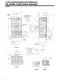
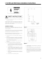
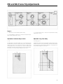
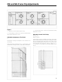
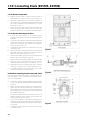
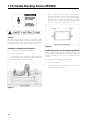
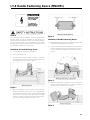
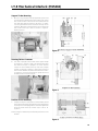
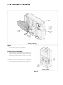
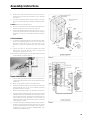
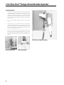
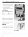
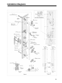
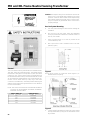
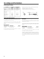
With the circuit breaker handle in the OFF position, align
the motor operator mechanism rollers (indicator to be in
OFF position) and the circuit breaker handle by rotating
the lead screw (6) with a screwdriver. The lead screw
access hole is at the bottom of the motor operator (Figure
2).
G. Close and latch the mechanism cover
H.
Complete the desired control connections and electrically test the motor operator system before reenergizing
the breaker power terminals in accordance with the
electrical operation.
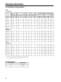
Electrical Characteristics
AAAA
AA
AAAA
AAAA
AA
CatalogAAAA
Numbers
VoltsAAAA
AC AAAAAAAA
Amperes
AAAA
AAAA
AA
AAAA
AAAA
AAAA
AAAA
AAAA
AA
AAAA
AAAA
AA
AAAA
AAAA
AAAA
AAAA
AAAA
AA
MOMN6120
120
22.7 Amperes In Rush
MOMN6120L
MOMN6240
MOMN6240L
13.9 Amperes In Running
240
7.2 Amperes In Rush
6.1 Amperes In Running
Electrical Operation
With the breaker and the operating mechanism in the OFF
position, press the ON button to energize the motor The action
will close the breaker. When the breaker handle reaches the
ON position, the motor circuit is disconnected by an internal
limit switch.
With the breaker and the operating mechanism in the ON
position, press the OFF button to energize the motor. The
action will open the breaker. When the breaker handle reaches
the OFF position, the motor circuit is disconnected by an
internal limit switch.
When the circuit breaker trips automatically, there is no
external indication that the breaker has tripped unless a
separate Bell Alarm accessory (contact Siemens for appropriate catalog number) is provided to energize a customer
furnished warning device. After the circuit breaker trips automatically, it is necessary to press the OFF button to move the
breaker handle to the reset position.
Automatic Reset
For automatic reset, an auxiliary switch (contact Siemens for
appropriate catalog number) is used to return the breaker to
the OFF/RESET position after it has been tripped. This auxiliary switch is mounted inside the breaker and wired in parallel
with the OFF button. When the breaker trips, the auxiliary
switch closes, energizing the motor circuit which moves the
breaker to the OFF/RESET position.
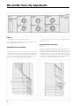
After the motor operated mechanism has reset the breaker,
the motor operator internal limit switch opens the circuit. To
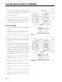
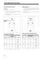
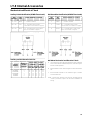
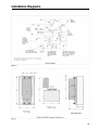
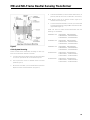
provide automatic reset, the ON push button must be a single
pole, double throw device and it must be wired per Figure 3.
Manual Operation
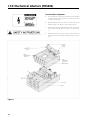
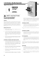
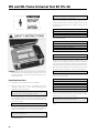
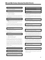
Operate the two cover latches and swing the hinged motor
operator cover away from the breaker to expose the breaker
handle. To return to electrical operation, follow the installation
instructions on page 45 deleting Steps B and C. After operation checks are complete, restore to normal operation.
46
Allign rollers and handle