1
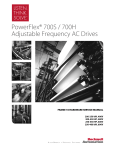
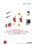
PowerFlex® 700S and 700H Frames
10…12 Rectifier Module Replacement Kit
Installation Instructions
ATTENTION: To avoid an electric shock hazard, ensure that all
power to the drive has been removed before performing the
following.
ATTENTION: To avoid an electric shock hazard, verify that the
voltage on the bus capacitors has discharged completely before
servicing. Check the DC bus voltage at the Power Terminal Block by
measuring between the +DC and -DC terminals, between the +DC
terminal and the chassis, and between the -DC terminal and the
chassis. The voltage must be zero for all three measurements.
ATTENTION: HOT surfaces can cause severe burns. Do not touch
the heatsink surface during operation of the drive. After
disconnecting power allow time for cooling.
ATTENTION: Hazard of permanent eye damage exists when using
optical transmission equipment. This product emits intense light and
invisible radiation. Do not look into SynchLink fiber-optic ports or
SynchLink fiber-optic cable connectors.
ATTENTION: This drive contains ESD (Electrostatic Discharge)
sensitive parts and assemblies. Static control precautions are required
when installing, testing, servicing or repairing this assembly.
Component damage may result if ESD control procedures are not
followed. If you are not familiar with static control procedures,
reference A-B publication 8000-4.5.2, “Guarding Against
Electrostatic Damage” or any other applicable ESD protection
handbook.
ATTENTION: The sheet metal cover and mounting screws on the
ASIC Board located on the power structure are energized at (-) DC
bus potential high voltage. Risk of electrical shock, injury, or death
exists if someone comes into contact with the assembly.
What This Kit Includes
•
•
•
•
Rectifier module
Rectifier DC+ bus bar (2)
Bus bar insulator sheet
Rectifier insulator sheet
Do not begin the installation before reading Important Parts Information on
page 2.
Publication PFLEX-IN023A-EN-P
2
Important Parts Information Important: Due to a change in the SCR modules used in the rectifier module
provided in this kit, the rectifier module DC+ bus bars and
insulator material provided in this kit must be used. Therefore, the
existing rectifier module DC+ bus bar and insulator material must
not be reused when installing this rectifier module kit. See details
below.
Rectifier Modules
Rectifier module with round terminals
Rectifier module with rectangular
terminals provided in this kit
Rectifier Module DC+ Bus Bars
Frame 10 and 12 rectifier DC+ bus bar
Frame 11 rectifier DC+ bus bar
Bus bar for round
SCR terminals
A
Bus bar for round
SCR terminals
A>B
A
A>B
Bus bar for rectangular
SCR terminals provided
in this kit
B
Publication PFLEX-IN023A-EN-P
B
Bus bar for rectangular
SCR terminals provided
in this kit
3
Bus Bar and Rectifier Module Insulator Material
The insulator sheet that is placed between the main DC- and DC+ bus bars for rectifier modules with round
SCR terminals is one piece. The insulator material provided with this kit is two pieces, one sheet for between
the main DC- and DC+ bus bars and one to cover the rectifier module.
Bus bar insulator material
provided in this kit
Tools That You Need
Rectifier module insulator
material provided in this kit
•
•
•
•
•
•
POZIDRIV screwdriver
Hexalobular screwdriver
Socket wrenches and extensions
Torque wrench
Wire cutter
PowerFlex 700H and 700S maintenance stand for Rittal TS8 enclosures only
(catalog string: 20-MAINSTD) (recommended)
• Lifting equipment capable of securing, holding and lifting the 210 kg (463
lb) frame 11 power structure
• Multi-meter - Digital multi meter, capable of ac and dc voltage, continuity,
resistance, capacitance measurements, and forward diode bias tests
POZIDRIV® is a registered trademark of Phillips Screw Company.
Publication PFLEX-IN023A-EN-P
4
Understanding Torque Figures in Illustrations
Icons and numbers in the assembly illustrations indicate how to tighten
hardware after re-assembly:
Fastener Type:
POZIDRIV Screw
Hexalobular
(TORX) Screw
Hexagonal Screw
Tool Type and Size:
PZ = POZIDRIV screwdriver bit
T = Hexalobular (TORX) screwdriver bit
xx mm = Socket wrench
HEX = Hexagonal screwdriver/bit
PZ2
4 N•m
(35 lb•in)
Tightening Torque
Hexagonal Bolt
Hexagonal Nut
ATTENTION: A hazard of personal injury and/or equipment
damage exists if the hardware securing power components in the
drive is not installed in the same location from which it was removed,
according to size, and the specified torque is not applied, where
indicated. Take the appropriate steps to ensure that the location and
size of hardware has been noted during disassembly and that proper
torque is applied as indicated during re-assembly.
What You Need to Do
Publication PFLEX-IN023A-EN-P
❐ Step 1:
❐ Step 2:
❐ Step 3:
❐ Step 4:
❐ Step 5:
❐ Step 6:
❐ Step 7:
❐ Step 8:
❐ Step 9:
Remove power from the drive
Remove the protective covers from the drive
Remove the power structure from the enclosure
Remove the existing rectifier module
Install the new rectifier module
Install the power structure in the enclosure
Complete the circuit tests
Install the protective covers
Document the change
5
Step 1: Remove Power
from the Drive
ATTENTION: To avoid an electric shock hazard, verify that the
voltage on the bus capacitors has discharged completely before
servicing. Check the DC bus voltage at the Power Terminal Block by
measuring between the +DC and -DC terminals, between the +DC
terminal and the chassis, and between the -DC terminal and the
chassis. The voltage must be zero for all three measurements.
Remove power before making or breaking cable connections. When
you remove or insert a cable connector with power applied, an
electrical arc may occur. An electrical arc can cause personal injury
or property damage by:
• sending an erroneous signal to your system’s field devices,
causing unintended machine motion
• causing an explosion in a hazardous environment
Electrical arcing causes excessive wear to contacts on both the
module and its mating connector. Worn contacts may create electrical
resistance.
1. Turn off and lock out input power. Wait five minutes.
2. Verify that there is no voltage at the drive’s input power terminals.
3. Check the DC bus voltage at the Power Terminal Block by measuring
between the +DC and -DC terminals, between the +DC terminal and the
chassis, and between the -DC terminal and the chassis. The voltage must be
zero for all three measurements.
L1
L2
L3
I
O
Publication PFLEX-IN023A-EN-P
6
Step 2: Remove the
Protective Covers from the
Drive
To remove the protective covers, you must first move the control frame and then
remove the air flow plate.
1. Loosen the T8 hexalobular screws that hold the control frame to the drive
enclosure (remove screws on early frame 10 drives).
2. Swing the control frame out and away from the power structure.
=
or
Screws
600 mm wide control frame shown
Publication PFLEX-IN023A-EN-P
Frame 10 drives, from early production runs, have
holes instead of slots for these screws. You must
completely remove the screws from these drives in
order to move the control frame.
7
3. Remove the four T8 hexalobular screws that secure the airflow plate to the
drive and slide the airflow plate off the enclosure frame.
Frame 10 enclosure shown
Airflow plate
Screws
Publication PFLEX-IN023A-EN-P
8
4. Remove the four M5 POZIDRIV screws that secure the top and bottom
protective covers to the main front protective cover and remove the top and
bottom protective covers.
5. Remove the four M5 POZIDRIV screws that secure the main front
protective cover to the drive and remove the protective cover.
6. On frame 10 and 12 drives only, remove the side protective covers.
4
6
4
5
6
5
PZ2
3.0 N•m
(26.5 lb•in)
5
5
4
5
Frame 10 covers shown
4
Publication PFLEX-IN023A-EN-P
9
Step 3: Remove the Power In order to remove the power structure from the enclosure you must first remove
the power and ground wiring.
Structure from the
Enclosure
For terminal locations, refer to Figure 1 below for frame 10 and 12 drives and
Figure 2 on page 10 for frame 11 drives.
1. Remove the insulator material from between the input terminals.
2. Remove the input wiring from the following terminals:
–
Frames 10 and 12 - L1, L2, L3 and DC-, DC+ (if present) on the power
structure
–
Frame 11 - 1L1, 1L2, 1L3 and 2L1, 2L2, 2L3 (except 690V AC input
460A and 502A drives, 1L1, 1L2, 1L3 only) and DC-, DC+ (if present)
on the power structure
3. Remove the motor wiring from terminals U/T1, V/T2, W/T3 on the power
structure.
4. Remove the ground connection from the power structure.
Figure 1 Frame 10 and 12 Drives
Frame 10 power
structure shown
DC Input Power
Connection Terminals
19 mm
40 N•m
(354 lb•in)
Motor Connection
Terminals
19 mm
40 N•m
(354 lb•in)
Remove Insulator Material
from between Terminals
AC Input Power
Connection Terminals
19 mm
40 N•m
(354 lb•in)
Ground
Connection
17 mm
40 N•m
(354 lb•in)
Publication PFLEX-IN023A-EN-P
10
Figure 2 Frame 11 Drives
Remove Insulator Material
from between Terminals
DC Input Power
Connection Terminals
AC Input Power
Connection Terminals
19 mm
40 N•m
(354 lb•in)
19 mm
40 N•m
(354 lb•in)
H
Motor Connection
Terminals
19 mm
40 N•m
(354 lb•in)
Publication PFLEX-IN023A-EN-P
L
H
L
H
L
Ground
Connection
17 mm
40 N•m
(354 lb•in)
11
5. Remove the bolts that secure the power structure to the drive enclosure (see
Figure 3 below for frame 10 and 12 and Figure 4 on page 12 for frame 11).
6. Follow the instructions in the PowerFlex 700S and 700H High Power
Maintenance Stand, Installation Instructions, publication PFLEX-IN014, to
assemble the maintenance stand.
Note: The maintenance stand is designed for removing power structures from
drives supplied in Rittal TS8 enclosures only. An alternate means of removal
is necessary for other types of enclosures.
7. Remove the power structure by sliding it onto the rails of the maintenance
stand.
Important: Do not pull on any of the cables, terminals or circuit board
mounts when removing the power structure from the
enclosure.
Figure 3 Frame 10 and 12 Drives
Frame 10 power
structure shown
Remove bolts
Remove bolts
Publication PFLEX-IN023A-EN-P
12
Figure 4 Frame 11 Drives
Remove bolts
H
L
H
L
H
L
Remove bolts
The steps for removing the rectifier module(s) from a frame 10 and 12 size drive
Step 4: Remove the
Existing Rectifier Module(s) are different than a frame 11 size drive. Refer to Remove the Rectifier
Module(s) from a Frame 10 or 12 Drive on page 13 or Remove the Rectifier
Module from a Frame 11 Drive on page 22.
Publication PFLEX-IN023A-EN-P
13
Remove the Rectifier Module(s) from a Frame 10 or 12 Drive
The rectifier module(s) on frame 10 and 12 drives are contained in the right side
of the power structure(s).
Frame 12
Frame 10
Rectifier module(s) located on
right side of power structure(s)
Note: Cut any cable ties securing control and power cables as necessary in order
to complete the following procedures. When re-assembling the drive
components, all control and power cables must be secured with cable ties in the
same manner as they were prior to removal.
Important: Mark all connections and wires before removal to avoid incorrect
wiring during reassembly.
Publication PFLEX-IN023A-EN-P
14
1. Remove the two M4x8 hexalobular screws that secure the control power
supply wires to the DC- and DC+ bus bars above the Gate Driver board and
remove the wires.
2. Loosen, but do not remove, the eight M10 hex nuts that secure the DC- and
DC+ connective bus bars to the drive.
Rectifier board
DCDC+
Loosen, but do not
remove, hex nuts
Remove screws
T20
1.0 N•m
(8.8 lb•in)
17 mm
40 N•m
(354 lb•in)
3. For drives with a series “A” rectifier circuit board (catalog number
20-VB00459 for 400/480V AC input drives, 20-VB00460 for 600/690V AC
input drives), disconnect the wires from connectors X10, X11, X12 and X13
on the board (see Figure 5 on page 15). For drives with a series “B” rectifier
circuit board (catalog number 20-VB00461 for 400/480V AC input drives,
20-VB00462 for 600/690V AC input drives), disconnect the wires from
connectors X10, X11, X12, X13, X21 and X31, X22 and X32, and X23 and
X33 on the rectifier board (see Figure 6 on page 15).
Publication PFLEX-IN023A-EN-P
15
Figure 5 Series A Rectifier Circuit Board
X9
X100
X50
X11
X12
X10
X6
X101
X13
X8
T20
1.5 N•m
(13.3 lb•in)
J3
J7
J11
X3
X41
X1
X2
X4
Figure 6 Series B Rectifier Circuit Board
X8
X9
X100
X12
X33 X23
X11
X32 X22
X10
X31 X21
X50
X6
X101
X13
T20
1.5 N•m
(13.3 lb•in)
X3
X2
X41
X1
X4
Publication PFLEX-IN023A-EN-P
16
4. If the common mode jumper is in the lowered position (as show below),
remove the M4x8 hexalobular screw that secures the jumper to the bracket
connected to the rectifier board.
Important: Note the position of the jumper before removal and ensure that
it is placed in the same position when the rectifier board is
installed.
Top of Power
Structure
Common mode jumper
Rectifier circuit board
Do not remove screw at X41
on rectifier circuit board
T20
1.5 N•m
(13.3 lb•in)
Remove screw
5. Remove the eight hexalobular screws that secure the rectifier board to the
drive (do not remove the screw at X41) and remove the board from the
rectifier module. Two M4x12 screws at X8 and X9. The remaining screws
are M4x8.
6. Lift the insulator material and remove the M10x20 bolts and washers that
secure the AC input cables and SCR terminal bus bars to the rectifier
module’s SCR terminals and remove the AC input cables and terminal bus
bars.
AC input cables
Terminal bus bars
Remove bolts
17 mm
14 N•m
(124 lb•in)
Publication PFLEX-IN023A-EN-P
17
7. Remove the six M10x20 bolts and washers that secure the DC- and DC+
rectifier bus bars and power cable to the SCRs on the rectifier module and
remove the bus bars and power cable.
Important: Do Not reuse the existing DC+ rectifier bus bar.
Do Not reuse existing DC+ bus bar
Top of Power
Structure
Remove bolts
17 mm
14 N•m
(124 lb•in)
Remove bolts
Power cable
Publication PFLEX-IN023A-EN-P
18
8. For 400/480V AC input drives, remove the three hexalobular screws that
secure the balancing resistor wires to the main bus bars. For 600/690V AC
input drives, remove the four hexalobular screws that secure the balancing
resistor wires to the main bus bars.
Important: Note the color (if unique) and location of each resistor
connector wire. Mark all connections and wires before
removal to avoid incorrect wiring during reassembly.
400/480V AC
Input Drives
T20
1.5 N•m
(13.3 lb•in)
Balancing resistors
Remove M4x8 screws
Remove M6x20 screw
T30
4.0 N•m
(35.4 lb•in)
600/690V AC
Input Drives
T20
1.5 N•m
(13.3 lb•in)
Balancing resistors
Remove M4x8 screws
Remove M4x8 screw
T20
1.5 N•m
(13.3 lb•in)
9. Remove the six M6x20 hexalobular screws that secure the snubber
capacitor assembly to the power module.
Snubber capacitor
assembly
T30
5.0 N•m
(44.2 lb•in)
Remove screws
Publication PFLEX-IN023A-EN-P
19
10. Remove the bus bars and insulator sheets from the drive. The steps to
remove the bus bars from a 400/480V AC input drive are different than the
steps to remove the bus bars from a 600/690V AC input drive. Refer to
Remove the Bus Bars from a 400/480V AC Input Drive below or Remove
the Bus Bars from a 600/690V AC Input Drive on page 20.
Remove the Bus Bars from a 400/480V AC Input Drive
–
Remove the six M6x20 hexalobular screws that secure the outer bus bar
to the drive and remove the bus bar and the loose bus bar insulator
sheet.
–
Remove the three M6x20 hexalobular screws that secure the main DCbus bar to the drive and remove the main DC- bus bar and the loose bus
bar insulator sheet.
–
Remove the three M6x16 hexalobular screws that secure the main DC+
bus bar to the drive and remove the main DC+ bus bar and the loose
capacitor insulator sheet.
DC+ Bus Bar
T30
5.0 N•m
(44.2 lb•in)
Outer Bus Bar
T30
4.0 N•m
(35.4 lb•in)
Bus bar insulator sheets
Capacitor
insulator
sheet
Do Not reuse this
insulator sheet.
Replace with new
insulator sheet.
DC- Bus Bar
T30
5.0 N•m
(44.2 lb•in)
Publication PFLEX-IN023A-EN-P
20
Remove the Bus Bars from a 600/690V AC Input Drive
–
Remove the four M6x25 hexalobular screws that secure the outer bus
bar to the drive and remove the bus bar and the loose bus bar insulator
sheet.
–
Remove the four M6x20 hexalobular screws that secure the next bus bar
to the drive and remove the bus bar and the loose bus bar insulator
sheet.
–
Remove the two M6x20 hexalobular screws that secure the main DCbus bar to the drive and remove the main DC- bus bar and the loose bus
bar insulator sheet.
–
Remove the two M6x16 hexalobular screws that secure the main DC+
bus bar to the drive and remove the main DC+ bus bar and the loose
capacitor insulator sheet.
Outer Bus Bar
T30
4.0 N•m
(35.4 lb•in)
Bus bar
insulator sheets
DC- Bus Bar
Do Not reuse this
insulator sheet.
Replace with new
insulator sheet.
Capacitor
insulator sheet
DC+ Bus Bar
T30
4.0 N•m
(35.4 lb•in)
Publication PFLEX-IN023A-EN-P
21
11. Remove the eight M4x8 POZIDRIV screws that secure the rectifier module
to the drive frame and remove the module.
Remove screws
PZ2
1.5 N•m
(13.3 lb•in)
12. Continue with Step 5: Install the New Rectifier Module on page 43.
Publication PFLEX-IN023A-EN-P
22
Remove the Rectifier Module from a Frame 11 Drive
The rectifier module(s) on frame 11 drives are contained in the V and W phase
power structure(s). 690V AC input 460A and 502A frame 11 drives only have
one rectifier module contained in the V phase power structure.
U Phase
V Phase
W Phase
H
L
H
L
H
L
Rectifier modules located on
sides of power structures
Note: Cut any cable ties securing control and power cables as necessary in order
to complete the following procedures. When re-assembling the drive
components, all control and power cables must be secured in the same manner
as they were prior to removal.
Important: Mark all connections and wires before removal to avoid incorrect
wiring during reassembly.
Publication PFLEX-IN023A-EN-P
23
ATTENTION: The sheet metal cover and mounting screws on the
ASIC Board located on the power structure are energized at (-) DC
bus potential high voltage. Risk of electrical shock, injury, or death
exists if someone comes into contact with the assembly.
1. Remove the four M4x8 POZIDRIV screws that secure the ASIC board
cover to the assembly and lift the cover off the assembly - you must unplug
the cable for the ASIC board assembly fan from connector X1 on the ASIC
board in order to remove the cover.
Upper-left corner of drive
ASIC assembly
Remove screws
PZ2
1.5 N•m
(13.3 lb•in)
Publication PFLEX-IN023A-EN-P
24
2. Carefully disconnect the fiber-optic cables from sockets H1…H13 of the
ASIC board and carefully set them aside (see illustration below).
ATTENTION: Hazard of permanent eye damage exists when
using optical transmission equipment. This product emits intense
light and invisible radiation. Do not look into fiber-optic ports or
fiber-optic cable connectors.
Important: Minimum inside bend radius for fiber-optic cable is 25.4 mm (1.0
in.). Any bends with a shorter inside radius can permanently
damage the fiber-optic cable. Signal attenuation increases with
decreased inside bend radii.
3. Disconnect the cables from connectors X2, X3, X4, X5, X6, X10 and X11
(and X9 and X15, if present) on the front of the ASIC board, and set them
aside.
Fiber Optics
X6
PZ2
3.0 N•m
(26.5 lb•in)
X9
X15
H1 H2 H3 H4 H5 H6 H7
X2
X1
X11
X10
H8 H9 H10 H11 H12 H13
X3
X4
X5
Fiber Optics
4. Remove the five POZIDRIV screws that secure the ASIC assembly to the
drive and remove the assembly.
Publication PFLEX-IN023A-EN-P
25
5. Carefully disconnect the fiber-optic cables from sockets H15 and H16 on
each of the three gate driver boards and carefully set them aside (see
illustration below).
ATTENTION: Hazard of permanent eye damage exists when
using optical transmission equipment. This product emits intense
light and invisible radiation. Do not look into fiber-optic ports or
fiber-optic cable connectors.
Important: Minimum inside bend radius for fiber-optic cable is 25.4 mm (1.0
in.). Any bends with a shorter inside radius can permanently
damage the fiber-optic cable. Signal attenuation increases with
decreased inside bend radii.
6. Remove the cables from connectors X6 and the DC+/DC- terminals from
the connector at the bottom of the three gate driver boards.
Fiber Optics
H15
H16
Gate driver
board locations
X6
+
-
Remove wires from terminals: +
–
Publication PFLEX-IN023A-EN-P
26
7. Remove the two screws that secure the wires for the ASIC board power
supply to the DC+ and DC- bus bars and disconnect the cables for the fan
power and control from the connectors as indicated below. The fan power
wires connect to the base of the fuse holder on the V phase module.
8. Remove the air flow sheet from below the gate driver boards.
ASIC board power
connections
DC-
Remove screws
Rectifier signal
connectors
DC+
Remove air
flow sheet
PZ2
5.0 N•m
(44.2 lb•in)
Fan signal
connectors
Fan signal
connector
Fan power connections
on fuse holder
Publication PFLEX-IN023A-EN-P
27
9. For PowerFlex 700H drives, continue with step 12 on page 28.
For PowerFlex 700S drives only, carefully disconnect the fiber-optic cables
from sockets J4 and J5 on the voltage feedback board and carefully set them
aside.
ATTENTION: Hazard of permanent eye damage exists when
using optical transmission equipment. This product emits intense
light and invisible radiation. Do not look into fiber-optic ports or
fiber-optic cable connectors.
Important: Minimum inside bend radius for fiber-optic cable is 25.4 mm (1.0
in.). Any bends with a shorter inside radius can permanently
damage the fiber-optic cable. Signal attenuation increases with
decreased inside bend radii.
10. Disconnect the DC bus connection cable from connector J2 and the motor
feedback connection cable from connector J3 on the voltage feedback
board.
11. Disconnect the cable from connector J8 on the voltage feedback board.
J2
J3
J4 J5
Voltage feedback
board location
J8
Publication PFLEX-IN023A-EN-P
28
12. The V and W phase modules must be removed from the power structure in
order to remove the rectifier modules. Therefore, you must lift the power
structure off the maintenance stand and place it, rear side of the unit down,
on a clean, suitable work surface. Follow the steps below to lift and move
the power structure.
a. Fasten the lifting hardware to the holes in the flanges on the top of the
power structure, symmetrically, in at least two holes. The maximum
angle between the cables must be no more than 45 degrees.
Maximum angle
45 degrees
210 kg (463 lb)
b. Lift the power structure off of the maintenance stand and place it, rear
side down, on the work surface.
Note: Power structure shown with
protective covers. Complete the
previous steps to remove the covers
and disconnect control wiring before
lifting and moving the power structure.
Publication PFLEX-IN023A-EN-P
29
13. For drives with DC bus supply terminals, remove the six M10 nuts and
washers that secure the bus bars that connect the DC– and DC+ terminals to
the horizontal bus bars and remove the bus bars.
DC-
DC+
Remove nuts
17 mm
40 N•m
(354 lb•in)
Remove bus bars
Remove nuts
17 mm
40 N•m
(354 lb•in)
Note: Power cables not
shown for clarity only.
Publication PFLEX-IN023A-EN-P
30
14. Remove the four M10 bolts and washers that secure the power cables to the
rectifier circuit output terminals.
15. Remove the four M10 nuts and washers that secure the other end of the
power cables to the DC– and DC+ collector bus bars and remove the cables.
Power cables
Remove bolts from
output terminals
17 mm
20 N•m
(177 lb•in)
Remove nuts
from bus bars
17 mm
20 N•m
(177 lb•in)
Publication PFLEX-IN023A-EN-P
31
16. Remove the four remaining nuts and washers that secure the DC– and DC+
collector bus bars to the drive, and remove the bus bars and insulator
material between them.
Important: The insulator material must be installed between the bus bars
during installation.
DC- and DC+
bus bars
Remove nuts
17 mm
20 N•m
(177 lb•in)
Publication PFLEX-IN023A-EN-P
32
17. Remove the six M10 nuts and washers that secure the AC supply cables to
the AC input terminals and remove the cables. Note: Frame 11 690V AC
input, 460A and 502A drives, only have one set of AC input terminals and
therefore one set of AC supply cables.
Remove nuts
17 mm
40 N•m
(354 lb•in)
AC supply cables
Publication PFLEX-IN023A-EN-P
33
18. Remove the eight POZIDRIV screws that secure the terminal assembly to
the drive and remove the assembly.
PZ2
4.0 N•m
(35.4 lb•in)
Remove screws
Terminal
assembly
Remove screws
Remove screws
Publication PFLEX-IN023A-EN-P
34
19. Remove the four M10 hexagonal screws that secure each of the V and W
phase modules to the drive frame.
Remove screws
HEX8
20 N•m
(177 lb•in)
Rectifier circuit board
(on side of phase module)
Remove screws
Publication PFLEX-IN023A-EN-P
HEX8
20 N•m
(177 lb•in)
35
20. Remove the six M5 and six M6 POZIDRIV screws that secure the upper
sheet metal plate of the power structure frame to the lower frame and
remove the upper metal plate.
Remove M5 screws
Remove M6
screws
PZ2
5.0 N•m
(44.3 lb•in)
Remove M5 screws
Remove M6
screws
PZ3
5.0 N•m
(44.3 lb•in)
21. Carefully remove the phase module from the top of the drive frame.
22. For drives with a series “A” rectifier circuit board (catalog number
20-VB00459 for 400/480V AC input drives, 20-VB00460 for 600/690V AC
input drives), disconnect the wires from connectors X10, X11, X12 and X13
on the rectifier board (see Figure 7 on page 36). For drives with a series “B”
rectifier circuit board (catalog number 20-VB00461 for 400/480V AC input
drives, 20-VB00462 for 600/690V AC input drives), disconnect the wires
from connectors X10, X11, X12, X13, X21 and X31, X22 and X32, and
X23 and X33 on the rectifier board (see Figure 8 on page 36).
Publication PFLEX-IN023A-EN-P
36
Figure 7 Series A Rectifier Circuit Board
X9
X100
X50
X11
X12
X10
X6
X101
X13
X8
T20
1.5 N•m
(13.3 lb•in)
J3
J7
J11
X3
X41
X1
X2
X4
Figure 8 Series B Rectifier Circuit Board
X8
X9
X100
X12
X33 X23
X11
X32 X22
X10
X31 X21
X50
X6
X101
X13
T20
1.5 N•m
(13.3 lb•in)
X3
X2
X41
X1
X4
Publication PFLEX-IN023A-EN-P
37
23. If the common mode jumper is in the lowered position (as show below),
remove the M4x8 hexalobular screw that secures the jumper to the bracket
connected to the rectifier board.
Important: Note the position of the jumper before removal and ensure that
it is placed in the same position when the rectifier board is
installed.
Top of Power
Structure
Common mode jumper
Rectifier circuit board
Do not remove screw at X41
on rectifier circuit board
T20
1.5 N•m
(13.3 lb•in)
Remove screw
24. Remove the eight screws that secure the rectifier board to the drive (do not
remove the screw at X41) and remove the board from the rectifier module.
Two M4x12 screws at X8 and X9. The remaining screws are M4x8.
25. Remove the three M5 nuts and three M4x8 hexalobular screws that secure
the snubber capacitors to the DC+ bus bar and SCR terminal bus bars and
remove the capacitors.
Remove nuts
8 mm
1.5 N•m
(13.3 lb•in)
Remove screws
T20
1.5 N•m
(13.3 lb•in)
Publication PFLEX-IN023A-EN-P
38
26. Remove the M10 bolts and washers that secure the AC input supply cables
and SCR terminal bus bars to the rectifier module and remove the cables
and bus bars from the rectifier module.
Remove bolts
17 mm
12 N•m
(106 lb•in)
AC supply cables
Terminal bus bars
27. Remove the six M10x20 bolts and washers that secure the DC- and DC+
rectifier bus bars to the rectifier module and remove the bus bars.
Important: Do Not reuse the existing DC+ rectifier bus bar.
Do Not reuse existing DC+ bus bar
Remove bolts
17 mm
12 N•m
(106 lb•in)
Publication PFLEX-IN023A-EN-P
39
28. For 400/480V AC input drives, remove the three hexalobular screws that
secure the balancing resistor wires to the main bus bars. For 600/690V AC
input drives, remove the four hexalobular screws that secure the balancing
resistor wires to the main bus bars.
Important: Note the color (if unique) and location of each resistor
connector wire. Mark all connections and wires before
removal to avoid incorrect wiring during reassembly.
400/480V AC
Input Drives
T20
1.5 N•m
(13.3 lb•in)
Balancing resistors
Remove M4x8 screws
Remove M6x20 screw
T30
4.0 N•m
(35.4 lb•in)
600/690V AC
Input Drives
T20
1.5 N•m
(13.3 lb•in)
Balancing resistors
Remove M4x8 screws
Remove M4x8 screw
T20
1.5 N•m
(13.3 lb•in)
29. Remove the six M6x20 hexalobular screws that secure the snubber
capacitor assembly to the power module and bus bars.
Snubber capacitor
assembly
T30
5.0 N•m
(44.2 lb•in)
Remove screws
Publication PFLEX-IN023A-EN-P
40
30. Remove the bus bars and insulator sheets - the steps to remove the bus bars
from a 400/480V AC input drive are different than the steps to remove the
bus bars from a 600/690V AC input drive. Refer to Remove the Bus Bars
from a 400/480V AC Input Drive below or Remove the Bus Bars from a
600/690V AC Input Drive on page 41.
Remove the Bus Bars from a 400/480V AC Input Drive
–
Remove the six M6x20 POZIDRIV screws that secure the outer bus bar
to the drive and remove the bus bar and the loose bus bar insulator
sheet.
–
Remove the three M6x20 POZIDRIV screws that secure the main DCbus bar to the drive and remove the main DC- bus bar and the loose bus
bar insulator sheet.
–
Remove the three M6x20 POZIDRIV screws that secure the main DC+
bus bar to the drive and remove the main DC+ bus bar and the loose
capacitor insulator sheet.
DC+ Bus Bar
PZ3
5.0 N•m
(44.2 lb•in)
Capacitor insulator sheet
Do Not reuse this
insulator sheet.
Replace with new
insulator sheet.
Publication PFLEX-IN023A-EN-P
Outer Bus Bar
PZ3
5.0 N•m
(44.2 lb•in)
Bus bar insulator sheets
DC- Bus Bar
PZ3
5.0 N•m
(44.2 lb•in)
41
Remove the Bus Bars from a 600/690V AC Input Drive
–
Remove the four M6x25 hexalobular screws that secure the outer bus
bar to the drive and remove the bus bar and the loose bus bar insulator
sheet.
–
Remove the four M6x20 hexalobular screws that secure the next bus bar
to the drive and remove the bus bar and the loose bus bar insulator
sheet.
–
Remove the two M6x20 hexalobular screws that secure the main DCbus bar to the drive and remove the main DC- bus bar and the loose bus
bar insulator sheet.
–
Remove the two M6x16 hexalobular screws that secure the main DC+
bus bar to the drive and remove the main DC+ bus bar and the loose
capacitor insulator sheet.
Outer Bus Bar
T30
4.0 N•m
(35.4 lb•in)
Bus bar
insulator sheets
DC- Bus Bar
Do Not reuse this
insulator sheet.
Replace with new
insulator sheet.
Capacitor
insulator sheet
DC+ Bus Bar
T30
4.0 N•m
(35.4 lb•in)
Publication PFLEX-IN023A-EN-P
42
31. Remove the eight M4x8 POZIDRIV screws that secure the rectifier module
to the drive frame and remove the module.
Remove screws
PZ2
1.5 N•m
(13.3 lb•in)
32. Continue with Step 5: Install the New Rectifier Module below.
Publication PFLEX-IN023A-EN-P
43
Step 5: Install the New
Rectifier Module
Install the new rectifier module, in the reverse order of removal.
Refer to Step 4: Remove the Existing Rectifier Module(s) on page 12.
ATTENTION: A hazard of personal injury and/or equipment
damage exists if the rectifier DC+ bus bar for round SCR terminals is
installed on the rectifier module provided with this kit. Do Not reuse
the rectifier DC+ bus bar that was used on the round SCR terminals
and install the rectifier DC+ bus bar provided with this kit only.
Important: You must only install the rectifier DC+ bus bar provided with this
kit. See illustration below.
DC+ bus bar for
round SCR terminals
(Do Not reuse this
bus bar)
Bus bar may touch SCR
terminal if installed
DC+ bus bar for
rectangular SCR terminals
provided in this kit
(install this bus bar only)
Bus bar provided in this kit
does not touch SCR terminal
Important: You must only install the new insulator sheet provided with the kit
over the rectifier module.
New insulator sheet
Align holes in
new insulator
sheet over
rectifier AC input
terminal tabs.
Publication PFLEX-IN023A-EN-P
44
Step 6: Install the Power
Structure in the Enclosure
Install the power structure in the drive enclosure in the reverse order of removal.
Refer to Step 3: Remove the Power Structure from the Enclosure on page 9.
Step 7: Complete the
Circuit Tests
Forward and Reverse Biased Diode Tests for Major Power Components
A forward biased diode test checks the semiconductor junctions between the
terminals and measures the voltage drop across those junctions. To pass each
test, the meter must display a voltage near 0.5V. If the test finds a short, the
meter will display “.000.” If the test finds an open circuit or reversed polarity,
the meter will display “.0L” (zero load).
A reverse biased diode test should find an open circuit, and the meter should
display “.0L” (zero load).
Forward biased
test on
PN-junction
+
Reverse biased
test on
PN-junction
~0.5V
+
~.0L
-
There is a series A and series B rectifier circuit board for each voltage class. The
tests you can perform and the results of those tests vary depending on which
series of board is in your drive. Verify the board catalog number before
completing the appropriate tests below.
Voltage Class
400/480V AC
600/690V AC
Rectifier Circuit Board Catalog Number
Series A
Series B
20-VB00459
20-VB00461
20-VB00460
20-VB00462
1. Verify that no power is applied to the drive.
2. Disconnect all motor leads from the drive.
3. Complete the forward and reverse biased diode tests on the rectifier
modules (if present) as indicated in Measurement Points for Forward and
Reverse Diode Tests Frame 10 and 12 Drives on page 45 or Measurement
Points for Forward and Reverse Diode Tests Frame 11 Drives on page 47.
Publication PFLEX-IN023A-EN-P
45
Measurement Points for Forward and Reverse Diode Tests Frame 10 and 12 Drives
DC- DC+
DC- DC+
Cat No.
FIELD INSTALLED OPTIONS:
DANGER
DC BUS CONDUCTORS AND CAPACITORS
OPERATE AT HIGH VOLTAGE. REMOVE POWER
AND WAIT 5 MINUTES BEFORE SERVICING
1U/T1
2V/T2
1234567890-*
1V/T2
DANGER
DC BUS CONDUCTORS AND CAPACITORS
OPERATE AT HIGH VOLTAGE. REMOVE POWER
AND WAIT 5 MINUTES BEFORE SERVICING
1W/T3
2U/T1
2W/T3
1L1
1L2
1L3
2L1
2L2
2L3
Power Structure #1
Power Structure #2
Series A Rectifier Circuit Board - Rectifier Module Tests
Table A Forward Biased Diode Tests on Rectifier Module(s)
Meter Leads
+
DC+
1L1
DC+
1L2
DC+
1L3
1L1
DC1L2
DC1L3
DC(1)
Nominal meter reading
Meter should beep once and value should gradually rise to about 0.5V(1)
The actual voltage reading may vary depending upon your equipment. If your readings are not near 0.5V, verify
that the actual voltage measured is consistent for the Rectifier module and the Output Power modules.
Publication PFLEX-IN023A-EN-P
46
Table B Reverse Biased Diode Tests on Rectifier Module(s)
Meter Leads
+
1L1
DC1L2
DC1L3
DCDC+
1L1
DC+
1L2
DC+
1L3
Nominal meter reading
Meter should display “.0L” (zero load)
Important: If the drive fails any of these measurements, verify that all
connections have been properly made for the appropriate rectifier
module.
Series B Rectifier Circuit Board - Rectifier Module Tests
Table C Forward Biased Diode Tests on Rectifier Module(s)
Meter Leads
+
DC+
1L1
DC+
1L2
DC+
1L3
1L1
DC1L2
DC1L3
DC-
Nominal meter reading
Meter should beep once and value should gradually rise to about 1.0 V(1)
The value should gradually rise to about 0.35V(2)
(1)
The actual voltage reading may vary depending upon your equipment. If your readings are not near 1.0V, verify
that the actual voltage measured is consistent for the Rectifier module and the Output Power modules.
(2)
The actual voltage reading may vary depending upon your equipment. If your readings are not near 0.35V,
verify that the actual voltage measured is consistent for the Rectifier module and the Output Power modules.
Table D Reverse Biased Diode Tests on Rectifier Module(s)
Meter Leads
+
1L1
DC1L2
DC1L3
DCDC+
1L1
DC+
1L2
DC+
1L3
Nominal meter reading
Meter should display “.0L” (zero load)
Important: If the drive fails any of these measurements, verify that all
connections have been properly made for the appropriate rectifier
module.
Publication PFLEX-IN023A-EN-P
47
Measurement Points for Forward and Reverse Diode Tests Frame 11 Drives
Figure 9 Measurement Points for Forward and Reverse Diode Tests
DC+
DC-
U/T1
1L1
V/T2
1L3
1L2
W/T3
2L1
2L3
2L2
Note: 600V ac input, 460A and 502A frame 11
drives only have one rectifier module.
Series A Rectifier Circuit Board - Rectifier Module Tests
Table E Forward Biased Diode Tests on Rectifier Module(s)
L1
L2
L3
DCDCDC(1)
Meter Leads
+
DC+
DC+
DC+
L1
L2
L3
Nominal meter reading
The value should gradually rise to about 0.5V(1)
The actual voltage reading may vary depending upon your equipment. If your readings are not near 0.5V, verify
that the actual voltage measured is consistent for the Rectifier module(s) and the Output Power modules.
Publication PFLEX-IN023A-EN-P
48
Table F Reverse Biased Diode Tests on Rectifier Module(s)
Meter Leads
+
L1
DCL2
DCL3
DCDC+
L1
DC+
L2
DC+
L3
Nominal meter reading
The meter should display “.0L” (zero load)
Important: If the drive fails any of these measurements, verify that all
connections have been properly made for the appropriate rectifier
module.
Series B Rectifier Circuit Board - Rectifier Module Tests
Table G Forward Biased Diode Tests on Rectifier Module(s)
L1
L2
L3
DCDCDC-
Meter Leads
+
DC+
DC+
DC+
L1
L2
L3
Nominal meter reading
The value should gradually rise to about 1.0V(1)
The value should gradually rise to about 0.35V(2)
(1)
The actual voltage reading may vary depending upon your equipment. If your readings are not near 1.0V, verify
that the actual voltage measured is consistent for the Rectifier module(s) and the Output Power modules.
(2)
The actual voltage reading may vary depending upon your equipment. If your readings are not near 0.35V,
verify that the actual voltage measured is consistent for the Rectifier module(s) and the Output Power modules.
Table H Reverse Biased Diode Tests on Rectifier Module(s)
Meter Leads
+
L1
DCL2
DCL3
DCDC+
L1
DC+
L2
DC+
L3
Nominal meter reading
The meter should display “.0L” (zero load)
Important: If the drive fails any of these measurements, verify that all
connections have been properly made for the appropriate rectifier
module.
Step 8: Install the
Protective Covers
Publication PFLEX-IN023A-EN-P
Install the protective covers on the drive in reverse order of removal.
Refer to Step 2: Remove the Protective Covers from the Drive on page 6.
49
Step 9: Documenting the
Change
Record the rectifier module installation on the Field Installed Option label.
Related Documentation
Allen-Bradley publications are available on the internet at
www.rockwellautomation.com/literature.
For
Programming and troubleshooting information on PowerFlex
700H drives
Programming and troubleshooting information on PowerFlex
700S Phase II drives
Information on installing Frame 9-14 PowerFlex 700H and
700S drives
Information on troubleshooting and repairing PowerFlex 700H
and 700S frame 10 drives
Information on troubleshooting and repairing PowerFlex 700H
and 700S frame 11 drives
Information on troubleshooting and repairing PowerFlex 700H
and 700S frame 12 drives
Read this document
PowerFlex 700H Programming Manual
Publication No.
20C-PM001
PowerFlex 700S with Phase II Control User Manual
20D-UM006
Installation Instructions - PowerFlex 700H and 700S Frame 9-14 Drives
PFLEX-IN006
PowerFlex 700H and 700S Frame 10 Hardware Service Manual
PFLEX-TG002
PowerFlex 700H and 700S Frame 11 Hardware Service Manual
PFLEX-TG003
PowerFlex 700H and 700S Frame 12 Hardware Service Manual
PFLEX-TG004
Publication PFLEX-IN023A-EN-P
U.S. Allen-Bradley Drives Technical Support - Tel: (1) 262.512.8176, Fax: (1) 262.512.2222, Email: [email protected], Online: www.ab.com/support/abdrives
www.rockwellautomation.com
Power, Control and Information Solutions Headquarters
Americas: Rockwell Automation, 1201 South Second Street, Milwaukee, WI 53204 USA,Tel: (1) 414.382.2000, Fax: (1) 414.382.4444
Europe/Middle East/Africa: Rockwell Automation, Vorstlaan/Boulevard du Souverain 36, 1170 Brussels, Belgium,Tel: (32) 2 663 0600, Fax: (32) 2 663 0640
Asia Pacific: Rockwell Automation, Level 14, Core F, Cyberport 3, 100 Cyberport Road, Hong Kong,Tel: (852) 2887 4788, Fax: (852) 2508 1846
Publication PFLEX-IN023A-EN-P – March, 2010
Copyright © 2010 Rockwell Automation, Inc. All rights reserved. Printed in USA.