1
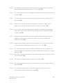
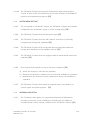
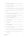
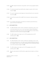
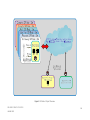
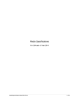
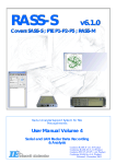
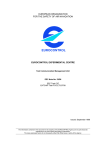
SECTION F TECHNICAL SPECIFICATIONS SSR MODE S PROJECT AT SIX SITES JANUARY 2012 F-1 PART 1 SSR MODE S SYSTEM and Other Equipment SSR MODE S PROJECT AT SIX SITES JANUARY 2012 F-2 LIST OF CONTENTS 1. SSR MODE S EQUIPMENT for EACH SITE ........................................................................ 4 1.1. FUNCTIONAL REQUIREMENTS ...................................................................................... 4 1.2. PERFORMANCE REQUIREMENTS................................................................................. 12 1.3. SPECIFIC REQUIREMENTS ............................................................................................ 17 2. DUAL CHANNEL MODE S SITE MONITOR for EACH SITE ............................................ 26 2.1. FUNCTIONAL REQUIREMENTS ................................................................................... 26 2.2. SPECIFIC REQUIREMENTS ........................................................................................... 26 3. NETWORK AND COMMUNICATION REQUIREMENTS.................................................... 27 3.1. GENERAL......................................................................................................................... 27 3.2. NETWORK EQUIPMENT REQUIREMENTS................................................................... 27 3.3. COMMUNICATION CABLE REQUIREMENTS ............................................................... 31 4. SPECIAL TOOL AND TEST EQUIPMENT REQUIREMENTS............................................. 33 4.1. SPECIAL TOOL REQUIREMENTS.................................................................................. 33 4.2. TEST EQUIPMENT REQUIREMENTS ............................................................................ 33 ANNEX A: GLOSSARY ............................................................................................................ 37 ANNEX B: REFERENCE DOCUMENTS .................................................................................. 40 ANNEX C: FIGURE ................................................................................................................. 41 SSR MODE S PROJECT AT SIX SITES JANUARY 2012 F-3 1. SSR MODE S EQUIPMENT for EACH SITE 1.1. FUNCTIONAL REQUIREMENTS 1.1.1. GENERAL 1.1.1.1. The SSR Mode S System shall be able to operate on Mode 1, 2, A, C, S as defined in ICAO Annex 10, Amendment 85, as follow; [FE] a) Mode 1 b) Mode 2 c) Mode A d) Mode C e) Mode A/C/S all-call f) Mode A/C only all-call g) Mode S only all-call h) Broadcast i) Selective (Roll call) 1.1.1.2. The SSR Mode S System shall provide surveillance functions and standard length communication transactions as stated below: [FE] a) b) c) d) e) f) g) h) i) j) Surveillance altitude request Surveillance altitude reply Surveillance identity request; Surveillance identity reply; Comm A altitude request; Comm B altitude reply; Comm A identity request; Comm B identity reply; Multi-site All-call Lockout protocols; Basic data protocols including: Flight status; Capability reporting; k) Standard length communication protocols: Comm A; Comm A broadcast; Ground initiated Comm B; Air initiated Comm B; SSR MODE S PROJECT AT SIX SITES JANUARY 2012 F-4 Comm B broadcast; Enhanced Comm B protocol for level 5 transponders. 1.1.1.3. The SSR Mode S System shall operate on extended length communication transactions as stated below: [FE] (a) Comm C; (b) Comm D; (c) Multi-site uplink Extended Length Message (ELM) protocol; (d) Non selective uplink ELM; (e) Multisite downlink ELM protocol; (f) Non selective downlink ELM 1.1.1.4. The SSR Mode S System shall be capable of providing functionality as listed below: [FE] a) Mode A and Mode C decodes ; b) ICAO 24-bit aircraft address; c) Transponder Capability Report; d) Automatic Reporting of Aircraft Identification; e) Flight Status. f) Ground Speed g) Roll Angle; h) True Track Angle; i) Track Angle Rate; j) Selected Altitude; k) Magnetic Heading; l) Indicated Airspeed; m) Mach Number; n) Barometric Altitude Rate; o) Inertial Vertical Velocity; p) True Airspeed. 1.1.1.5. The SSR Mode S shall support aircraft identification protocols, including [FE] (a) Aircraft identification reporting; (b) Aircraft capability reporting; (c) Change of aircraft identification 1.1.1.6. The SSR Mode S System must have II Code and SI Code. [FE] SSR MODE S PROJECT AT SIX SITES JANUARY 2012 F-5 1.1.1.7. The SSR Mode S System shall be able to detect and recognize the special civil codes 7500, 7600 and 7700. [FE] 1.1.1.8. The SSR Mode S System shall be able to detect and recognize the special Military Emergency reply train, and set the appropriate fields in the target report. [FE] 1.1.1.9. The SSR Mode S System shall be able to detect and recognize the special Military Identity reply train, and set the appropriate fields in the target report. [FE] 1.1.1.10. For item 1.1.1.7, 1.1.1.8, 1.1.1.9 the appropriate identifier bits, as specified in Eurocontrol Standard Radar Data Exchange Part 1 ASTERIX, SUR.ET1.ST05.2000STD-01-01, Edition:1.30 shall be set in the output message. [FE] 1.1.1.11. The SSR Mode S System shall be able to discriminate between false and real, non-unique addressed Mode S targets. [FE] 1.1.1.12. The non-unique address Mode S targets shall be flagged in the ASTERIX data item I048/030 Warning Error/Conditions code 16 “Duplicated or Illegal Mode S Aircraft Address”. [FE] 1.1.1.13. Both channels (active and standby channel) of the SSR Mode S System shall process data simultaneously, for redundancy. [FE] 1.1.1.14. The active channel shall carry out the target reports (plots and tracks) to the BACC, SVB APC and the MDF. [FE] 1.1.1.15. The standby channel shall carry out the target reports (plots and tracks) to the MDF. [FE] 1.1.1.16. The false brackets or phantom brackets shall be rejected. [FE] 1.1.1.17. The SSR Mode S System shall be able to detect genuine targets and reject asynchronous replies. [FE] 1.1.1.18. Genuine targets, including targets with C2/SPI spacing, shall not be rejected as phantoms. [FE] SSR MODE S PROJECT AT SIX SITES JANUARY 2012 F-6 1.1.1.19. The SSR Mode S System shall eliminate false target such as reflections and side lobes. [FE] 1.1.1.20. The SSR Mode S System shall be capable of automatically extracting, via Ground Initiated Comm Bs (GICBs) requests, a minimum of four (4) Comm Bs data selector (BDS) registers for all aircraft in surveillance responsibility. [FE] 1.1.1.21. The SSR Mode S System shall enable the programmed extraction of any kind of BDS register through these GICBs requests. [FE] 1.1.1.22. These GICBs requests shall be programmed on a periodic basis. [FE] 1.1.1.23. The BDS registers to be extracted, the periodicity of extraction of each BDS and their priority shall be site-dependant parameters programmed at the CMF. [FE] 1.1.1.24. The validity of the data in the BDS registers shall be verified based on the requirements specified in ICAO Doc. 9871, A.2.2.1. Only valid data can be used by the SSR Mode S System. [FE] 1.1.1.25. GICBs extraction shall not be attempted by the system if the BDS register is not supported by the aircraft installation. [FE] 1.1.1.26. The SSR Mode S System shall track all the aircraft, including aircraft with duplicated addresses and maintain the roll-call list. [FE] 1.1.1.27. Target reports identified as reflections shall not be output as real targets but all the tracks including those consisting of false targets shall be initiated and maintained. [FE] 1.1.1.28. False targets due to any of the causes listed below shall be identified (marked) as false in the category indicated and rejected (i.e. not output as real targets): [FE] a) False targets due to multipath; b) False targets at similar range to, but at different azimuths from, originating real target at short range (ring around); c) False targets at similar azimuths to, but at increasingly longer ranges from an originating real target (in-line multipath); SSR MODE S PROJECT AT SIX SITES JANUARY 2012 F-7 d) False targets split from an originating real target due to Antenna beam distortion or splitting as a result of multipath or local obstruction diffraction (splits); e) False targets with angular separations from an originating target due to reflection of the interrogations and/or transponder responses by reflecting surfaces in the signal paths (reflections). 1.1.1.29. For time sharing, the allocation of channel capacity between Mode A/C all-call, Mode S all-call and Mode S roll call can be adjusted by AEROTHAI engineers based upon actual demand. [FE] 1.1.1.30. The SSR Mode S System shall be able to produce a single, double or triple interlace mode (i.e. A,1,C or A,2,C) on consecutive interrogation pulse trains. [FE] 1.1.1.31. The interlaced modes programs shall be selectable on a per sector basis (each Antenna revolution representing at least 32 sectors). [FE] 1.1.1.32. The SSR Mode S system shall be able to interrogate in azimuth selectable IISLS for Mode A/C all-call and Mode S all-call. [FE] 1.1.1.33. The output power shall be able to programs as a function of azimuth over a number of unequal sectors, not less than 32, over 360°, the Sum and Control powers pertinent to both Mode S all-call and Mode A/C all-call operation. [FE] 1.1.1.34. The SSR Mode S system shall be able to operate on RSLS. [FE] 1.1.1.35. The Sensitivity Time Control (STC) or an equivalent threshold method shall be provided and possible selected either a linear or programmable action. [FE] 1.1.2. CONTROL AND MONITORING FUNCTION (CMF) 1.1.2.1. The SSR Mode S System shall be controlled both locally and remotely by the Control and Monitoring Function (CMF). [FE] 1.1.2.2. The Control and Monitoring Function (CMF) of each SSR Mode S Site shall be performed from three (3) locations, as follows. [FE] a) The equipment room at each SSR Mode S Site; SSR MODE S PROJECT AT SIX SITES JANUARY 2012 F-8 b) The equipment room at each Control Tower (Control Tower at Don Mueang, Phitsanulok, Udon Thani, Roi Et, Chiang Rai and Chumphon); c) The surveillance processing room at BACC. 1.1.2.3. CMF at the three locations must have equal functionalities. [FE] 1.1.2.4. The control function of the CMF must be performed from only one location at a time. [FE] 1.1.2.5. The monitoring function of the CMF shall be available simultaneously at all locations of CMF. [FE] 1.1.2.6. Unauthorized alterations through the CMF shall be prevented by password entry. [FE] 1.1.2.7. A disconnection or a failure of the CMF shall not create an interruption to the operational service. [FE] 1.1.2.8. CMF shall control and monitor all functions and parameters of the SSR Mode S System, as described below: [FE] (a) Turn On/Off the dual Antenna drive motors; (b) Continue monitoring lubricant of moving parts and generate an alarm when the lubricant level is below normal. (in case of using oil lubricant) (c) Generate alarm and cease the Antenna rotation when anomaly operation (such as antenna motor over-heat or over-current) is detected; (d) Indicate the malfunction of an Antenna Azimuth Sensor. (e) Select Automatic or Manual changeover between the two (2) Channels; (f) Select and monitor operation condition; Active, Stand-by and Maintenance of the two (2) Channels; (g) Control and monitor the transmitter peak power output; (h) SET the output power level as desired in some sectors; (i) Set up the interlace and interval of transmission modes (1 ,2, A, C, S) for ATC services; (j) Determine the dependent site parameter for STC functional; (k) Set up the test target for functionality test purpose; (l) Select the Plots/Tracks outputs followed by the usage requirement; SSR MODE S PROJECT AT SIX SITES JANUARY 2012 F-9 (m) Indicate the status of BITE; (n) Monitor the system interface availability status; (o) Monitor the utilities status; (p) Configure the II Code and SI Code. (q) Modify SDPs data. 1.1.2.9. All controlled and monitored data shall be printed through a color laser printer at each location as specify in item 1.1.2.2.[FE] 1.1.2.10. The CMF shall be displayed in a graphical format. [FE] 1.1.2.11. The CMF shall provide the following statistical information (on a Scan or timely basis): [FE] (a) · · · · · · (b) Information about the data supplied to the ATC: Number of solo Mode S reports; Number of solo SSR reports; Number of code swaps; Number of reports with duplicated Mode S address; Number of test transponders; Number of test targets. The statistic information of the CPU loading. 1.1.2.12. The BITE shall register the faulty LRU and report through the CMF. [FE] 1.1.2.13. Response time of CMF control functions shall be no more than eight (8) seconds. [FE] 1.1.2.14. The CMF control functions at each location shall consume network bandwidth no more than 9600 bps. [FE] 1.1.3. BUILT IN TEST EQUIPMENT (BITE) FUNCTION 1.1.3.1. BITE shall be provided for on-line testing, and be able to detect any fault affecting the performance of the SSR Mode S System. [FE] 1.1.3.2. The on-line testing of the system shall work without any additional external test equipment. [FE] SSR MODE S PROJECT AT SIX SITES JANUARY 2012 F-10 1.1.4. TEST TARGET FUNCTION (TTF) 1.1.4.1. The SSR Mode S System shall be able to generate test target(s) in order to check the functionalities of the system. [FE] 1.1.4.2. When these test target(s) are output to the BACC and SVB APC, the corresponding ASTERIX Category 48 target report(s) shall be labeled accordingly with the bit “TST” set within the field I048/020 “Target Report Descriptor”. [FE] 1.1.4.3. Test target(s) shall be enabled or disable to be sent to BACC and SVB APC. [FE] 1.1.5. MAINTENANCE DISPLAY FUNCTION (MDF) 1.1.5.1. The Maintenance Display Function (MDF) of each SSR Mode S Site shall be performed at two (2) locations, as follows [FE] a) The equipment room at each SSR Mode S Site b) The equipment room at each Control Tower 1.1.5.2. MDF at the two locations must have equal functionalities. [FE] 1.1.5.3. The MDF shall be able to handle the target loads as specified in 1.2.7. [FE] 1.1.5.4. The MDF shall accept and display signals or data from its site in real-time, or from the data recording and playback facility, consisting of at least: [FE] a) Mode 1,2, A, C, S raw video signals; b) Plot/Track Information; c) Mode S elementary and enhanced surveillance information (ASTERIX Cat. 48) as specified in 1.1.1.4; d) Presentation of the currently operational local Surveillance (Radar) Coverage maps, for the following altitudes: 1000, 1500, 2000, 3000, 5000, 7000, 10000, 15000, 20000, 30000, 40000 feet; e) Data flagged as anomalies and false plots/tracks and NOT sent to BACC SVB-APC; f) Information (b), (c), (d) and (e) shall be displayed in a geographical presentation. g) A list of the Mode S aircraft under surveillance (Mode S address, aircraft ID, height & position) SSR MODE S PROJECT AT SIX SITES JANUARY 2012 F-11 h) can display information (d) and (e) from active or standby channel. 1.1.5.5. The MDF shall provide the operator with the ability to select any combination from the above list for display. [FE] 1.1.5.6. The symbology (and/or color) shall be provided to distinguish between different plot/track types. [FE] 1.1.5.7. A background map facility including Thailand boundary, airways, reporting points, and Terminal area shall be provided for up to 300 NM. radius of the origin. [FE] 1.1.6. DATA RECORDING AND PLAYBACK FUNCTION (RPF) 1.1.6.1. The RPF shall record and playback of the following data, but not be limited to: [FE] a) ASTERIX CAT 1, CAT2, CAT 34, CAT 48 information (including plot and track information) b) Status information 1.1.6.2. The data recording shall be recorded with time-stamp for up to 72 hours. [FE] 1.1.7. TIME FUNCTION 1.1.7.1. The Time Function shall provide time information to the SSR Mode S System for the purpose of synchronization and time-stamping. [FE] 1.1.7.2. The Time Function shall be capable to be interfaced with two (2) GPS Time Servers as external sources. [FE] 1.1.7.3. In the event that the GPS Time Server fails to deliver a time reference, the Time Function shall revert to the internal clock. This condition shall be reflected in the Time Source Status as part of the Station Configuration Status item of the ASTERIX Category 34 messages. [FE] 1.2. PERFORMANCE REQUIREMENTS SSR MODE S PROJECT AT SIX SITES JANUARY 2012 F-12 1.2.1. GENERAL 1.2.1.1. The Mode C shall be updated on the track for each Antenna revolution. [FE] 1.2.1.2. The target reports shall be sent to BACC, SVB APC for every Antenna revolution until the track is cancelled. [FE] 1.2.1.3. A track shall be initialized and maintained, both upon detection (Mode A and C and Mode S aircraft) or upon receiving supplementary data (Mode S aircraft only). [FE] 1.2.1.4. A track shall be cancelled when the track is not in the cone of silence and has not been updated within three Antenna revolutions. [FE] 1.2.1.5. During channel changeover, the SSR Mode S System shall continue service without any corruption to the output surveillance data. [FE] 1.2.1.6. The overall false target report ratio shall be less than 0.1%, measured over 50,000 target reports. [FE] 1.2.1.7. The overall multiple target report rate, measured over one hour, shall be less than one target per scan on average. [FE] 1.2.1.8. Mode A code and BDS 2,0 shall automatically be extracted by the SSR Mode S System when the last measured position of the track is older than 18 seconds. [FE] 1.2.1.9. When SSR Mode S System ceases to operate (due to complete power failure etc.), it shall be able to recover (upon the power return) automatically and maintain the operating condition before the interruption. [FE] 1.2.1.10. The performance requirements shall be met with all site operational parameters set following commissioning including antenna tilt, gain time control and any other variable thresholds. [FE] 1.2.1.11. The SSR Mode S System shall process up to four discrete, mutually overlapping replies simultaneously and rejecting all possible phantoms SSR MODE S PROJECT AT SIX SITES JANUARY 2012 F-13 produced by them, including C2/SPI phantoms. [FE] 1.2.1.12. The maximum drift of the internal clock shall be less than 20 milliseconds per month. [FE] 1.2.2. AVAILABILITY 1.2.2.1. By using the formula given below, the operational availability A(o) of coherent and full radar data from the MSSR Mode S system shall be greater than 99.98%. [FE] A(o) MTBF MTBF MTTR MTBF = Mean Time Between Failures in hours. MTTR = Mean Time To Repair in hours. 1.2.2.2. The Tenderer shall state the values of MTBF and MTTR for their use to calculate A(o). [FE] 1.2.2.3. The MTBF and MTTR in hours and the Availability shall be clearly shown in either each block diagram or in a list showing the equipment breakdown to functional unit level, with identification of specific common failure mode (e.g. switch over equipment). [FE] 1.2.2.4. The AAS (Antenna Azimuth Sensor) shall have MTBF of not less than 50,000 hours. [FE] 1.2.3. RADAR COVERAGE 1.2.3.1. The SSR Mode S System shall provide continuous coverage through 360º of azimuth and over a range of 0.5 NM to at least 256 NM at 12 rounds per minute (rpm) in clear line of sight. (for each Mode A/C,S as specified in 1.1.1.1) [FE] 1.2.3.2. The SSR Mode S System shall meet the proposed detail in the horizontal surveillance coverage diagrams, as specified in Section B, Item 6.3 Organization, Part 5-Other Documentation, a) Radar Coverage Diagram. [FE] 1.2.3.3. The vertical coverage shall be up to at least 66,000 ft. [FE] 1.2.4. DETECTION SSR MODE S PROJECT AT SIX SITES JANUARY 2012 F-14 1.2.4.1. Mode A/C probability of detection shall be greater than 97%., measured over 50,000 target reports. [FE] 1.2.4.2. Mode S probability of detection shall be at least 99%., measured over 50,000 target reports. The 99% of probability of detection shall be achieved in roll call with, on average, 2 GICB requests per aircraft. [FE] 1.2.4.3. Mode A only probability of correct and valid code detection shall be greater than 98%., measured over 50,000 target reports. [FE] 1.2.4.4. Mode A only probability of correct and valid code detection shall be greater than 92% when they are overlapping (separated in range by < 2NM)., measured over 50,000 target reports. [FE] 1.2.4.5. Mode C only probability of correct and valid code detection shall be greater than 96%., measured over 50,000 target reports. [FE] 1.2.4.6. Mode S only probability of correct and valid code detection shall be at least 99%, measured over 50,000 target reports. [FE] 1.2.4.7. The percentage of incorrect but validated Mode A codes shall be lower than 0.1%. [FE] 1.2.4.8. The percentage of incorrect but validated Mode C codes shall be lower than 0.1%. [FE] 1.2.4.9. Within a separation window area of 0 NM to less than 0.05 NM in range and 0º to 0.6º in azimuth, the overall probability of detecting two Mode A/C targets shall be at least 60%. [FE] 1.2.4.10. Within a separation window area of 0 NM to less than 0.05 NM in range and 0º to 0.6º in azimuth, the overall probability of detecting two Mode A/C targets with correct and valid Mode A, Mode C codes shall be at least 30%. [FE] 1.2.4.11. Within a separation window area of greater than 0.05 NM to less than 2 NM in range and by less than 0.6º in azimuth, the overall probability of detecting two Mode A/C targets shall be at least 98%. [FE] SSR MODE S PROJECT AT SIX SITES JANUARY 2012 F-15 1.2.4.12. Within a separation window area of greater than 0.05 NM to less than 2 NM in range and by less than 0.6º in azimuth, the overall probability of detecting two Mode A/C targets with correct and valid Mode A, Mode C codes shall be at least 90%. [FE] 1.2.4.13. Within a separation window area less than 2 NM in range and by more than 0.6º and by less than 4.8º in azimuth, the overall probability of detecting two Mode A/C targets shall be at least 98%. [FE] 1.2.4.14. Within a separation window area less than 2 NM in range and by more than 0.6º and by less than 4.8º in azimuth, the overall probability of detecting two Mode A/C targets with correct and valid Mode A, Mode C codes shall be at least 98%. [FE] 1.2.4.15. No more than one message segment containing false data of a Comm B or Comm D reply shall be delivered from SSR Mode S System in 107 messages. [FE] 1.2.4.16. The overall jump rate as being reports with the number of jumps divided by number of detected target reports shall be ≤ 0.05%. [FE] Note Jumps are target reports with position error higher than 1 degree in azimuth or 700 meter in range. 1.2.5. SURVEILLANCE POSITION ACCURACY 1.2.5.1. The slant range bias for any Mode shall be ≤ 1/128 NM. [FE] 1.2.5.2. The slant range random errors of Mode A/C shall be ≤ 30 meters RMS (1 sigma) [FE] 1.2.5.3. The slant range random errors of Mode S shall be ≤ 15 meters RMS (1 sigma) [FE] 1.2.5.4. The azimuth bias for elevation angles between 0º and +6º of any modes (A, C or S) shall be ≤ 0.022º. [FE] 1.2.5.5. The azimuth bias for elevation angles between 6º and 10º of any modes (A,C or S) shall be ≤ 0.033º. [FE] SSR MODE S PROJECT AT SIX SITES JANUARY 2012 F-16 1.2.5.6. The azimuth random errors of any modes (A,C or S) shall be ≤ 0.068º. [FE] 1.2.6. RANGE AND AZIMUTH PRECISION 1.2.6.1. The range precision shall be ≤ 1/128 NM at all ranges. [FE] 1.2.6.2. The azimuth precision shall be ≤ 0.022º at all ranges and azimuths. [FE] 1.2.6.3. The OBA precision shall be ≤ 0.022º. [FE] 1.2.7. TARGET LOADS The SSR Mode S System shall be able to process at least 900 transponder equipped aircraft and distribution of targets from 0.5 NM to 256 NM within one antenna revolution. [FE] 1.2.8. PROCESSING CAPABILITY 1.2.8.1. Each processor shall not be utilized for more than 50 % of processing time at 900 transponder equipped aircraft targets load within one antenna revolution. [FE] 1.2.8.2. At 900 transponder equipped aircraft targets load, the amount of Random Access Memory (RAM) and disk storage in used at any time shall not exceed 50% of that available capacity. [FE] 1.3. SPECIFIC REQUIREMENTS 1.3.1. GENERAL 1.3.1.1. Pulses shape of the modes in item 1.1.1.1 shall be defined in ICAO Annex 10 Volume 4 Amendment 85. [FE] SSR MODE S PROJECT AT SIX SITES JANUARY 2012 F-17 1.3.1.2. The SSR Mode S System shall process replies from transponders compliant with ICAO Annex 10 amendment 69, 71, 73 and 85. [FE] 1.3.1.3. The carrier frequency of all interrogations (uplink transmission) shall be 1,030 ± 0.01 MHz. [FE] 1.3.1.4. The minimum over-all receiver bandwidth shall be at least ± 4 MHz at the 3 dB points. [FE] 1.3.1.5. Mode A/C all-call period shall be selected for constant or stagger which stagger may be a fixed sequence, random or pseudo random. [FE] 1.3.1.6. As a minimum, the transmitter shall be capable of operation at peak power duty cycle of 63.7% over 2.4 millisecond length of time, repeated every 24 milliseconds. [FE] 1.3.1.7. Variation of the interrogate and control output powers shall allow a power variation at least over the range from maximum power to 12dB below maximum power. [FE] 1.3.1.8. Output power variation step for both interrogate and control channels shall be no greater than 2.0dB with an accuracy of ≤ +/- 1.0 dB. [FE] 1.3.1.9. The Pulse Repetition Frequency (PRF) for MODE A/C all-call and Mode S allcall period shall be adjustable from 50Hz to 250Hz with increments no greater than 1Hz. [FE] 1.3.1.10. IISLS shall be able to interrogate by transmitting both pulses P1 and P2 on the Control channel. [FE] 1.3.1.11. The receiver sensitivity shall be better than -85 dBm. [FE] 1.3.1.12. The isolation between channel A (1) and channel B (2) ports shall be greater than 40dB. [FE] 1.3.1.13. The isolation between ports of the same channel (i.e. with the receiver disconnected) shall be greater than 70dB. [FE] SSR MODE S PROJECT AT SIX SITES JANUARY 2012 F-18 1.3.1.14. The SSR Mode S System shall include bi-directional high power precision coupler in each of the Sum, Difference and Control channels to facilitate RF injection and measurement purpose. [FE] 1.3.2. SYSTEM ARCHITECTURE 1.3.2.1. The conceptual of SSR Mode S Project, the SSR Mode S System and network configuration are illustrated in Figure 1, 2 and 3 respectively. [FE] 1.3.2.2. The SSR Mode S System shall be Monopulse type. [FE] 1.3.2.3. The SSR Mode S System shall be dual channel, channel A (1) and B (2), complete with changeover capability. [FE] 1.3.2.4. The SSR Mode S System shall incorporate the necessary fault detection circuitry and switchover to the available channel. [FE] 1.3.2.5. The SSR Mode S System shall be equipped with an auto/manual switchover capability. [FE] 1.3.2.6. Each channel shall operate on any of the three conditions: [FE] a) Active: the channel is used for the operation; b) Stand-by: the channel is switched on and normally available for operation; c) Maintenance: the channel is under maintenance and is not available for operation. 1.3.2.7. The SSR Mode S System shall retain its selected state in the absence of control signals and power supplies. [FE] 1.3.3. ANTENNA SUBSYSTEM 1.3.3.1. The Contractor shall supply one Large Vertical Aperture (LVA) Antenna providing monopulse sum and difference channels with an additional omnidirectional control channel, suitable for the SSR Mode S System. [FE] SSR MODE S PROJECT AT SIX SITES JANUARY 2012 F-19 1.3.3.2. The LVA Antenna shall produce azimuth beam width between 2º and 3º at half power point (-3 dB). [FE] 1.3.3.3. The peak gain of the LVA Antenna shall not less than 26.0 dB relative to a lossless isotropic radiator. [FE] 1.3.3.4. The LVA Antenna shall operate in 4-pulses: Improved Interrogation Side Lobe Suppression (IISLS), and Received Side Lobe Suppression (RSLS) mode. [FE] 1.3.3.5. Voltage Standing Wave Ratio (VSWR) of the RF path shall be less than 1.5:1. [FE] 1.3.3.6. The insertion loss in RF path between the LVA Antenna and the SSR Mode S active channel shall be less than 2.0 dB. [FE] 1.3.3.7. For normal operation, the Antenna shall be rotated by the Antenna drive motors at 12 rounds per minute (rpm). [FE] 1.3.3.8. The Antenna turning rates shall be adjustable from 5 rpm or less to 15 rpm or more (≤ 5 rpm to ≥ 15 rpm). [FE] 1.3.3.9. Under normal condition, the Antenna shall be driven by duplicated motors simultaneously. [FE] 1.3.3.10. In case of one motor fails, the other single motor shall be able to drive the Antenna. [FE] 1.3.3.11. AEROTHAI engineer shall be able to select either one of the two motors to drive the Antenna. [FE] 1.3.3.12. The Antenna shall be provided with facilities for mechanical tilt adjustment and suitable locking devices. [FE] 1.3.3.13. Azimuth Count Pulses (ACP) and North Reference Pulse (NRP) shall be generated by two complete and independent Antenna Azimuth Sensors. [FE] 1.3.3.14. The ACP shall be at least 14 bit resolution without using interpolation techniques. [FE] SSR MODE S PROJECT AT SIX SITES JANUARY 2012 F-20 1.3.3.15. The NRP output shall be able to align within 1 ACP of the geographical North. [FE] 1.3.3.16. The Antenna Azimuth Sensor (AAS) shall be aligned to within 1 ACP of each other AAS. [FE] 1.3.3.17. The time for replacement and alignment of each AAS shall not be more than 53 minutes. [FE] 1.3.3.18. Each AAS shall provide ACP and NRP for both active and stand-by channels. [FE] 1.3.3.19. The Contractor shall supply and install the obstruction light (double lamp type) on the top of the antenna. 1.3.4. MDF WORKSTATION 1.3.4.1. The MDF Workstation shall include a multi-function keyboard, mouse, or the roller ball pointing device, and a color liquid crystal display (LED Backlight), with the size of greater than 20 inches measured diagonally, and the working desk fitted to all of the mentioned equipment. [CB] 1.3.4.2. The MDF hardware shall make use of a COTS workstation with a COTS operating system. [CB] 1.3.5. CMF WORKSTATION 1.3.5.1. The CMF Workstation shall include a multi-function keyboard, mouse, or the roller ball pointing device, a color liquid crystal display (LED Backlight) with the size of greater than 20 inches measured diagonally, and the working desk fitted to all of the mentioned equipment. [CB] 1.3.5.2. The CMF hardware shall make use of a COTS workstation with a COTS operating system. [CB] 1.3.5.3. The color laser printers for CMF shall be supplied at the locations, as follows . [CB] SSR MODE S PROJECT AT SIX SITES JANUARY 2012 F-21 a) The equipment room at each SSR Mode S Site b) The equipment room at each Control Tower c) The surveillance processing room at BACC 1.3.6. GPS TIME SERVER 1.3.6.1. Two (2) sets of GPS Time Server with GPS receiver shall provide time Information to the Time Function. [FE] 1.3.6.2. The GPS Time Server shall supply timing information through Ethernet 10/100 Base-Tx LAN port with standard Network Time Protocol (NTP) v2, v3 and v4. [FE] 1.3.7. SITE DEPENDENT PARAMETERS (SDP) 1.3.7.1. Site Dependent Parameters (SDPs) shall be stored in a suitable non-volatile medium. [FE] 1.3.7.2. SDPs shall not be hard-coded within any software of the system. [FE] 1.3.7.3. The adjustment of any SDP shall not require any alteration or recompilation of the software. [FE] 1.3.7.4. The design approach shall be capable of ensuring that SDPs will not change in the event of a switch-over of the active channel. [FE] 1.3.8. DATA TRANSMISSION 1.3.8.1. The surveillance data output shall be sent to BACC and SVB APC (dual channels). [FE] 1.3.8.2. The surveillance data output shall be selectable as follow; [FE] (a) Asterix Cat 1 and Cat 2 (b) Asterix Cat 34 and Cat 48 (c) Asterix Cat 1, Cat 2, Cat 34 and Cat 48 SSR MODE S PROJECT AT SIX SITES JANUARY 2012 F-22 1.3.8.3. ASTERIX Cat 1, Cat 2, Cat 34 and Cat 48 format shall be conformed to the requirements of: [FE] (a) Eurocontrol Standard Document for Radar Data Exchange Part 2a Transmission of Monoradar Data Target Reports, SUR.ET1.ST05.2000-STD02a-01, Edition : 1.1, August 2002; (b) Eurocontrol Standard Document for Radar Data Exchange Part 2b Transmission of Monoradar Service Messages, SUR.ET1.ST05.2000-STD02b-01, Edition : 1.0, November 1997; (c) Eurocontrol Standards Document for Data Exchange Part 1 ASTERIX, SUR.ET1.ST05.2000-STD-01-01, Edition: 1.30, November 2007; (d) Eurocontrol Standards Document for Surveillance Data Exchange Part 2b Transmission of Monoradar Service Messages, SUR.ET1.ST05.2000-STD2b-01, Edition: 1.27, May 2007; (e) Eurocontrol Standards Document for Surveillance Data Exchange Part 4 Transmission of Monoradar Target Reports, SUR.ET1.ST05.2000-STD-0401, Edition: 1.16, March 2009. 1.3.8.4. The surveillance data output shall be conformed with standard UAP (User Application Profile) as specified in 1.3.8.3. [FE] 1.3.8.5. The AEROTHAI engineer shall be able to select to send any data item of each Asterix Category as specified in 1.3.8.3. [FE] 1.3.8.6. The network protocol for transmitting the surveillance data shall be UDP/IP (unicast or multicast over Ipv4 or Ipv6), TCP/IP (client or server over Ipv4 or IPV6). [FE] 1.3.8.7. For multicast, the destination (Multicast address and UDP port) of each surveillance data output (CAT1/2 and CAT 34/48) shall be separated into difference logical port, and independently configurable by AEROTHAI Engineer. [FE] 1.3.8.8. The IPv4, IPv6, TCP, and UDP protocols shall comply respectively with the IETF RFC 791, 2460, 793 and 768. [FE] SSR MODE S PROJECT AT SIX SITES JANUARY 2012 F-23 1.3.9. Uninterrupted Power Supply (UPS). [CB] The contractor shall supply two (2) UPS units (parallel redundant) which supports Thailand electrical standard input. The power rating (performance) of each unit is suitable for supply the SSR Mode S system (including antenna subsystem) which backup time is at least 15 minutes at normal operating work load. 1.3.9.1 General Specification a) The UPS shall be complete with the rectifier which converts AC power to the regulated DC power. The regulated DC power shall float charge the batteries which is the power back up for invert on. The inverter shall invert the DC power again into AC system for supply to the critical load. The batteries of the UPS shall be able to supply the inverter at normal operating work load, in the event of utility line failure, at least 15 minutes. b) In the event of failure on overload exceeding system cope abilities the bypass switch shall transfer the load to the reserve AC supply without interruption. Upon restoration of the UPS function the load shall be retransferred to the UPS supply automatically without interruption c) The UPS shall be true on line double conversion according to VFI Class and microprocessors control. d) During maintenance operation on-off maintenance bypass switch shall connect the load to MEA electrical power. e) Overall efficiency not less than 90% at full load. f) Conform to IEC, EN, ISO 9001 standards or equivalent g) Battery (Rating Given For 25° C) - Type : Sealed Lead Acid & Maintenance Free - Design Life Time : not less than 10 Years - Certificate of Origin : Europe or USA h) Control and Monitor - Display : LCD (LED Back light) Display 1.3.9.2 Monitoring a) Operating status shall be shown on the personal computer with graphic or test-format display. The personal computer will be set up at ATC Control Tower or designated area. Communication cable shall be prepared as a data media. b) The status type shall be both operating status of UPS with graphic display and fault alarm/warning alarm with alerting sound which is one of fault alarm type. SSR MODE S PROJECT AT SIX SITES JANUARY 2012 F-24 1.3.10. ENVIRONMENTAL CONDITIONS 1.3.10.1. Internal Conditions. [FE] a) Any equipment housed within the equipment room at the site shall operate and maintain its full operational performance under the following conditions: Temperature: 0°C to +40°C; Relative Humidity ≥90%. b) COTS equipment may be employed in the equipment room, the following condition shall be considered acceptable for that equipment: [CB] Temperature +10 to +40°C. Relative Humidity ≥ 80%; 1.3.10.2. External Conditions [FE] (a) Any equipment not housed within the equipment room(s) including LVA antenna, turning gear together with any pedestal mounted electronics shall operate and maintain its full operational performance under following conditions: · Ambient Air Temperature: -40°C to +50°C; · Relative Humidity: Up to 100%; · Driving Rain: Up to 60 mm/h; · Wind resistance: In operation, bursts up to 160 km/h; · Wind resistance: In survival, bursts up to 220 km/h. (b) All external equipment Antenna and turning gear shall be resilient to salt atmospheres SSR MODE S PROJECT AT SIX SITES JANUARY 2012 F-25 2. DUAL CHANNEL MODE S SITE MONITOR for EACH SITE 2.1. FUNCTIONAL REQUIREMENTS [CB] (a) Operation in Modes 3/A, C and S; (b) Built in test and fault reporting; (c) User selectable attenuator from 0 to 50 dB range in 1 dB step; (d) Surveillance Identifier (SI) Capability; (e) Flight ID integrated into transponder controller; (f) Interrogation Modes 3/A, C, S Level 3; (g) User-selectable Altitude 0-99,000 ft in 1000-ft steps; (h) Support Mode S Formats 0, 4, 5, 11, 16, 20, 21, 24; (i) User-selectable range delay 0.3 - 250 NM in 0.1 NM steps; (j) User selectable 24 bit ICAO aircraft address; (k) User selectable Mode 3/A Code. (l) Ability to set BDS registers as follow, using a laptop computer: Aircraft/Flight Identification BDS 2,0; Selected Altitude BDS 4,0; True Track Angle BDS 5,0; Ground Speed BDS 5,0; True Airspeed BDS 5,0; Own Magnetic Heading BDS 6,0; Mach; Roll Angle; Indicated Airspeed; Barometric Altitude Rate; Inertial vertical velocity; 2.2. SPECIFIC REQUIREMENTS [CB] (a) Fully solid state; (b) Modular construction; (c) Directional Antenna; (d) Operated over input power 200 to 240 VAC, 50 Hz; (e) UPS backup available for at least 30 minutes; (f) One (1) set of laptop computer used for setting BDS registers. SSR MODE S PROJECT AT SIX SITES JANUARY 2012 F-26 3. NETWORK AND COMMUNICATION REQUIREMENTS 3.1. GENERAL 3.1.1. Network and communication systems shall be used for transmitting and receiving of plots/tracks/CMF/MDF data between each SSR Mode S Site, equipment room at each Control Tower, BACC and SVB APC. [FE] 3.1.2. Network and communication systems shall be designed in accordance with Figure 3, Annex C. [FE] 3.1.3. The contractor shall provide network and communication systems between each SSR Mode S Site and each Control Tower. [FE] 3.1.4. The Contractor shall be responsible for interfacing between SSR routers at each Control Tower (64 Kbps available bandwidth) and V.35 DCE AEROTHAI frame relay network ports only at each Control Tower. [FE] 3.1.5. The Contractor shall be responsible for interfacing between router/switch at SVB APC (64 Kbps available bandwidth) with V.35 DCE AEROTHAI frame relay network ports for SVB network equipment room. [FE] 3.1.6. The Contractor shall be responsible for interfacing between router/switch at BACC/ APC Center (64 Kbps available bandwidth) with V.35 DCE AEROTHAI frame relay network ports for BACC/ APC Center network equipment room. [FE] 3.1.7. The Contractor shall configure network systems for hot-standby or redundancy operations, in order to prevent having a single point of failure in the network systems. [FE] 3.1.8. The communication media between each SSR Mode S Site and each Control Tower shall be fiber optic cable, wireless links and copper wire cable. [FE] 3.2. NETWORK EQUIPMENT REQUIREMENTS 3.2.1. Layer-3 Ethernet Switch (per unit) [CB] 3.2.1.1. Functional Requirements [CB] SSR MODE S PROJECT AT SIX SITES JANUARY 2012 F-27 (a) The MAC address shall be configurable and shall support not less than 12,000 MAC address entries; (b) The unicast routes shall be configurable and shall support configuration for not less than 11,000 unicast routes; (c) The Internet Group Management Protocol (IGMP) groups and multicast routes shall be configurable and shall support up to 1000 configurations; (d) The maximum transmission unit (MTU) shall be configurable; (e) The mode of operation shall be trunk and access; (f) IP routing function for IP unicast routing protocols (Open Shortest Path First [OSPF], Interior Gateway Routing Protocol [IGRP], Enhanced IGRP [EIGRP], and Border Gateway Protocol Version 4[BGPv4]) shall be supported . 3.2.1.2. Performance Requirements [CB] a) The Switching Fabric shall be at least 32 Gbps; b) The forwarding rate shall be at least 38.7 mpps; 3.2.1.3. Specific Requirements [CB] a) A minimum of twenty four (24) Ethernet 10/100/1000 ports shall be provided; b) Four (4) small form-factor pluggable slots and two (2) SFP-Lx module shall be available as minimum; c) A minimum of one hundred and twenty eight (128) Megabytes of Dynamic Random Access Memory (DRAM) shall be available; d) A minimum of sixteen (16) Megabytes of flash memory shall be available; e) For bridging on Gigabit Ethernet ports, the MTU supported shall be at least 9018 bytes (Jumbo Frames); 3.2.2. Router (per unit) for BACC and SVB [CB] 3.2.2.1. Functional Requirements [CB] (a) The WAN port shall be capable of supporting DDN, Frame Relay, PPPoE, ATM, VPN, HDLC, ISDN, MPLS and ADSL; (b) The LAN ports shall support TCP/IP routing protocol; (c) The router provided shall be available software for TCP/IP and Voice routing, voice, VPN and security service; (d) IP routing function for IP unicast routing protocols (Open Shortest Path First (OSPF), Interior Gateway Routing Protocol (IGRP), Enhanced IGRP SSR MODE S PROJECT AT SIX SITES JANUARY 2012 F-28 (EIGRP) and Border Gateway Routing Protocol Version 4 (BGPv4) shall be supported. 3.2.2.2. Performance Requirements [CB] (a) The rate of transfer of data (speed) for WAN port shall be adjustable from a minimum of 64 Kbps to 2048 Mbps or greater; 3.2.2.3. Specific Requirements [CB] (a) The system memory (DRAM) shall be at least 1 Gigabytes; (b) Two hundred and fifty six (256) Megabytes of flash memory (compact flash) shall be provided as a minimum; (c) Four (4) interface slots, two (2) Service module slots and one (1) packet voice/data module slots be available as a minimum; (d) Four (4) High Speed WAN ports of V.35 DTE and cables shall be provided as a minimum; (e) Three (3) RJ-45 Gigabit Ethernet LAN ports with cables shall be provided as a minimum; (f) Four (4) FXo and four (4) FXs voice ports with cables shall be provide as a minimum; (g) The DSP compression algorithm utilized for voice ports shall comply with ITU G.729 standard or better capable of supporting Voice over IP and Voice over Frame Relay; (h) The voice connection shall be pre-assigned and switching; (i) One (1) ISM module shall be provided as a minimum; (j) The router shall be provided internal redundant AC power supply; 3.2.3. Router (per unit) for each SSR Mode S Site [CB] 3.2.3.1. Functional Requirements [CB] (a) The WAN port shall be capable of supporting DDN, Frame Relay, PPPoE, ATM, VPN, HDLC, ISDN, MPLS and ADSL; (b) The LAN ports shall support TCP/IP routing protocol; (c) The router provided shall be available software for TCP/IP and Voice routing, voice, VPN and security service; (d) IP routing function for IP unicast routing protocols (Open Shortest Path First (OSPF), Interior Gateway Routing Protocol (IGRP), Enhanced IGRP (EIGRP) and Border Gateway Routing Protocol Version 4 (BGPv4) shall be supported. SSR MODE S PROJECT AT SIX SITES JANUARY 2012 F-29 3.2.3.2. Performance Requirements [CB] (a) The rate of transfer of data (speed) for WAN port shall be adjustable from a minimum of 64 Kbps to 2048 Mbps or greater; 3.2.3.3. Specific Requirements [CB] (a) The system memory (DRAM) shall be at least 256 Megabytes; (b) Sixty four (64) Megabytes of flash memory (compact flash) shall be provided as a minimum; (c) Four (4) interface slots, one (1) Service module slots and one (1) packet voice/data module slots be available as a minimum; (d) Four (4) High Speed WAN ports of V.35 DTE and cables shall be provided as a minimum; (e) Two (2) RJ-45 Gigabit Ethernet LAN ports with cables shall be provided as a minimum; (f) Four (4) FXo and four (4) FXs voice ports with cables shall be provide as a minimum; (g) The DSP compression algorithm utilized for voice ports shall comply with ITU G.729 standard or better capable of supporting Voice over IP and Voice over Frame Relay; (h) The voice connection shall be pre-assigned and switching; (i) One (1) Enhanced-performance DES, 3DES, AES, and compression VPN encryption AIM module shall be provided as a minimum; 3.2.4. Wireless Link (per unit) [CB] 3.2.4.1. Performance Requirements [CB] (a) The Throughput shall be at least 50 Mbps; (b) The operation distance shall be at least 4 Km; (c) The operation frequency shall be adjustable within the band 5.150-5.850 GHz. 3.2.4.2. Specific Requirements [CB] (a) The Wireless Link shall operate within band 5.150-5.850 GHz Thailand free-license; (b) A minimum of one (1) Ethernet 10/100 Base-Tx and two (2) E1 with native TDM shall be provide; (c) The Air Link shall be at least AES 128 bits Encryption. SSR MODE S PROJECT AT SIX SITES JANUARY 2012 F-30 3.2.5. Ethernet to Serial Converter (per set) [FE] 3.2.5.1. Functional Requirements [FE] (a) Convert UDP/IP (Radar data CAT 34, CAT 48, CAT 1 and CAT 2) Multicast to HDLC protocol. (b) For multicast, the destination (Multicast address and UDP port) of each surveillance data input shall be configurable. 3.2.5.2. Specific Requirements [FE] (a) Interface Ethernet 10/100 Base-Tx with RS-232/V.24 synchronous serial port. (b) The data rate for serial port shall be adjustable from 9.6 Kbps to 64 Kbps or greater; (c) Not less than six (6) serial output ports shall be provided. 3.3. COMMUNICATION CABLE REQUIREMENTS 3.3.1. Fiber optic cable 3.3.1.1. Performance Requirements [CB] (a) Fiber Optic Cable shall be Maximum attenuation not over 0.35 dB/km at 1310nm and 0.21 dB/km at 1550 nm. (b) Operating Temperature -40 oC to 75 oC (c) Minimum Pulling Tension 3000 N 3.3.1.2. Specific Requirements [CB] (a) Fiber Optic Cable shall be designed for exterior installation with the medium density Polyethylene (MDPE), UV-Resistance, water blocking. The Fiber Optic type shall be a single mode and holds up to 24 cores. (b) Fiber Optic shall be loose-tube designed for used in the majority of outside-plant installation with all-dielectric, water penetration, and humidity resistance and optional armored. SSR MODE S PROJECT AT SIX SITES JANUARY 2012 F-31 (c) The Outer structure shall be Core Tube with the gel filling compound impedes water penetration for inner and Core Tube typically uses Swell able yarn as the primary tensile strength member and improved Rodent protection. (d) Fiber Optic Cable shall be Single mode type with standard ITU-T G.652.D. (e) Bending radius not over Static 10 time of core diameter or better and Dynamic 20 time of core diameter or better. (f) Contractor shall provide Fiber Optic installed at Airport Authority of Thailand Public Company Limited (AOT)’s area or Department of Aviation (DOA)’ s area for communicating between SSR Mode S Site and the Existing Air Traffic Control Tower. (g) Fiber Optic Connectors, Couplers, Patch Panel and Patch Cords Specification Connectors will be FC type, ceramic zirconia. Connector insertion loss not to exceed 0.4 dB. Connector Return loss more than 45 dB. Panel: Light guide Inter changeable Unit (LIU), Provide connector rack mount patch panel on frame rack with FC connector. 3.3.2. Copper wire cable 3.3.2.1. Specific Requirements [CB] (a) Contractor shall provide copper wire cable installed at AOT’s area or DOA’s area for communicating between New radar Tower and the Existing Air Traffic Control Tower for 50 pairs the qualification with APFSF standard. (b) Cable structure shall be used for exterior the outer jacket is medium density for underground conduit. (c) Cable structure shall be shielded with polyethylene with core covering, core binder tape, filling compound, insulated conductor and coating with aluminum not less than 0.2 mm. to protected signal cross talk. (d) Conductor construction wire shall be Tinned copper wire and diameter not less than 0.65 mm. (22 AWG). SSR MODE S PROJECT AT SIX SITES JANUARY 2012 F-32 4. SPECIAL TOOL AND TEST EQUIPMENT REQUIREMENTS 4.1. SPECIAL TOOL REQUIREMENTS 4.1.1. The Contractor shall supply the tools which are required for the following maintenance procedure: [FE] (a) Azimuth drive motor replacement; (b) Rotary joint replacement; (c) Main bearing replacement; 4.1.2. Hand tools which are equivalent to Snap-on hand tools complete metric set A stock#:9100GMBO. [CB] 4.1.3. The Contractor shall supply the tool for the MDF background map creation. 4.2. TEST EQUIPMENT REQUIREMENTS 4.2.1. Cable and Antenna Analyzer: [CB] 4.2.1.1. Functional Requirements [CB] (a) Cable and antenna analyzer 100KHz to 8 GHz; (b) One-port Cable loss and measurements; (c) Distance-to-fault measurements; (d) Built-in DC voltage supply; (e) Built-in spectrum analysis measurements; (f) Directional power measurements; (g) Remote control via LAN or USB; (h) Transmission measurement; (i) Network analyzer; (j) Vector voltmeter; (k) Two-port vector network analysis; 4.2.1.2. Specific Requirements [CB] (a) Spectrum Analysis Application; SSR MODE S PROJECT AT SIX SITES JANUARY 2012 F-33 (b) Power Meter Measurement Application; (c) Spectrogram Measurement Application; (d) Transmission Measurement Application; (e) Remote Control via USB or LAN Application; (f) Vector Network Analysis Application; (g) Vector Voltmeter Measurement Application; (h) Wideband Power Sensor , 1 nW to 100 mW, 50 MHz to 18 GHz; (i) USB Adapter (passive) for connecting power sensors; (j) RF Cable (length 1 m), N male/N female; (k) RF Cable (length 3 m), N male/N female; (l) Combined Open/Short/50 Ω Load Calibration Standard for calibrating the VSWR and DTF measurements, DC to 8 GHz; (m) Calibration Kit, N male, 50 Ω, Open/Short/Match/Through combination, 0 Hz to 8 GHz; (n) Calibration Kit, N female, 50 Ω, Open/Short/Match/Through combination, 0 Hz to 8 GHz; (o) Calibration Kit, 3.5 mm male, Open/Short/Match/Through combination, 0 Hz to 15 GHz; (p) Calibration Kit, 3.5 mm female, Open/Short/Match/Through combination, 0 Hz to 15 GHz; (q) Matching Pad, 50 Ω/75 Ω, bidirectional, 0 Hz to 2.7 GHz, N female/N male, load capacity 2 W, series resistor 25 Ω; (r) Matching Pad, 50 Ω/75 Ω, bidirectional, 0 Hz to 2.7 GHz, N female/N male, load capacity 2 W, series resistor 25 Ω; (s) Matching Pad, 50 Ω/75 Ω, bidirectional, 0 Hz to 1 GHz, BNC female/N male, load capacity 1 W; (t) Li-Ion Battery Pack, 6.75 Ah; (u) Battery Charger for Li-ion battery pack, 4.5 Ah/6.75 Ah; (v) 12 V Car Adapter; (w) Soft Carrying Bag (W × H × D: 260 mm × 360 mm × 280 mm); (x) Carrying Holster including chest harness and rain cover; (y) GPS Receiver; (z) Hard transit case. 4.2.2. Vector Signal Generators: [CB] 4.2.2.1. Functional Requirements [CB] (a) Built-in function generator; SSR MODE S PROJECT AT SIX SITES JANUARY 2012 F-34 (b) Frequency range 250 kHz to 6 GHz; (c) Internal baseband generator with 64 MSa and digital bus capacity (320 MB) of memory; 4.2.2.2. Performance Requirements [CB] (a) High output power with mechanical attenuator; (b) Enhanced phase noise performance; (c) High-stability time base 4.2.2.3. Specific Requirements [CB] (a) Output power +13 to -136 dBm at 1 to 3 GHz; (b) 6 GB internal hard drive; (c) Digital input and output connectivity with baseband studio digital interface module; (d) CD-ROM –English documentation set; (e) Service documentation, assembly level; (f) Service documentation, component level; (g) Commercial calibration certificate with test data; (h) Signal studio Software; (i) Waveform license 5-pack; (j) Front handle kit; (k) Transit Case. 4.2.3. Digital Storage Oscilloscopes: [CB] 4.2.3.1. Functional Requirements [CB] (a) Direct Print to Printer via USB Device and LAN Port. 4.2.3.2. Performance Requirements [CB] (a) 350 MHz Bandwidths; (b) Sample Rates up to 2 GS/s Real Time; 4.2.3.3. Specific Requirements [CB] (a) Four (4) Analog channels; (b) Sixteen (16) Digital channels; SSR MODE S PROJECT AT SIX SITES JANUARY 2012 F-35 (c) 12.1” XGA TFT LCD Display; (d) XGA video output port; (e) Built-in USB port; (f) FFT Standard; (g) At least four (4) probes; (h) 16 channel flying lead set logic probe; (i) RS-232/UART triggering and decode; (j) I2C/SPI serial decode option; (k) Transit Case with foam molding; (l) Soft carrying case; (m) Service Manual. 4.2.4. Digital Multimeter: [CB] 4.2.4.1. 4.2.4.2. Functional Requirements [CB] (a) True RMS AC + DC measurement; (b) Logging function with Trend Capture; (c) Multiple readings per display provide more information at a glance; (d) Frequency, capacitance, duty cycle and pulse width measurements; (e) Resistance, conductance, continuity and diode measurements; (f) Temperature and dBV/dBm with selectable reference; (g) PC interface for data exchange and closed case calibration; Specific Requirements [CB] (a) Hand-held Digital multimeter; (b) Large 50,000 count 320x240 (1/4 VGA) dot matrix display; (c) 100 kHz AC bandwidth for voltage and current; (d) Ergonomic high-impact case; (e) All inputs are protected to EN61010-1 CAT IV 600V/CAT III 1000V. CSA, TÜV listed and VDE Pending. (f) Software; (g) Soft Carrying Case ; (h) Cable adapter; (i) Temperature Thermocouple. SSR MODE S PROJECT AT SIX SITES JANUARY 2012 F-36 ANNEX A: GLOSSARY ˚C AAS ACC ACP AEROTHAI AICBs APC APP ASTERIX ATC ATCC BACC BDS BITE BKK Cat 1 Cat 2 Cat 34 Cat 48 CD-ROM CMF COTS CPN CTR dB DMK DSTC ELM FRUIT ft GDLP GICBs GPS HDLC Hz ICAO Degree Celsius Antenna Azimuth Sensor (or Azimuth Pulse Generator or Encoder) Area Control Center Azimuth Count (or Change) Pulses Aeronautical Radio of Thailand Ltd. Air Initiated COMM Bs Approach Control Approach Control Office All Purpose Structured Euro control Radar Information Exchange Air Traffic Control Air Traffic Control Centre Bangkok Area Control Center Comm B Data Selector Built In Test Equipment Bangkok ASTERIX Category 1 ASTERIX Category 2 ASTERIX Category 34 ASTERIX Category 48 Compact Disk-Read Only Memory Control and Monitoring Function Commercial Of The Shelf CHUMPHON CHIANG RAI Decibel DON MUEANG Digital Sensitivity Time Control Extended Length Message False Replies Unsynchronized In Time Feet (flight level (1FL = 100 ft) Ground Data Link Processor Ground Initiated Comm Bs Global Positioning Satellite High level Data Link Control Hertz International Civil Aviation Organisation SSR MODE S PROJECT AT SIX SITES JANUARY 2012 F-37 ICD IEEE IETF IISLS Km/h KW LAN LCD LRU LVA MB Mbps MDF MHz NM NMS NRP OBA OBI PCB Pd PRF PSL RAM RF ROT RPM RPF RSLS SVB SDP SLM SPI SSR STC TCP/IP TST UDP Interface Control Document Institution of Electrical and Electronics Engineers Internet Engineering Task Force Improved Interrogator Side Lobe Suppression Kilo meter per hour Kilo Watts Local Area Network Liquid Crystal Display Lowest Replaceable Unit Large Vertical Aperture (Rotating Antenna) Message COMM - B Mega bits per second Maintenance Display Function Mega Hertz Nautical Mile (1 NM = 1852 m) Network Management System North Reference Pulse Off Boresight Angle Off Boresight Indication Printed Circuit Boards Probability of Detection Pulse Repetition Frequency PHITSANULOK Random Access Memory Radio Frequency ROI ET Rounds Per Minute Data Recording and Playback Function Receiver Side Lobe Suppression SUVARNABHUMI Site Dependent Parameters Standard Length Message Special Position Identification Secondary Surveillance Radar Sensitivity Time Control Tele-Communication Protocol/ Internet Protocol Test Target User Datagram Protocol SSR MODE S PROJECT AT SIX SITES JANUARY 2012 F-38 UDN V VSWR UDON THANI Volt Voltage Standing Wave Ratio SSR MODE S PROJECT AT SIX SITES JANUARY 2012 F-39 ANNEX B: REFERENCE DOCUMENTS 1. ICAO Annex 10, third edition of Volume III & IV (incorporating Amendments 70-85 to second edition). 2. Mode S Subnetwork SARPs described as Volume III, Part 1, Chapter 5 to Amendment 85 of ICAO Annex 10, including appendices, November 2007. 3. Manual of SSR Systems, third edition (2004): ICAO Doc.9684. 4. Standard STFRDE ASTERIX documents: (a) EUROCONTROL Standard Document for Radar Data Exchange Part 1 ASTERIX, SUR.ET1.ST05.2000-STD-01-01, Edition: 1.30, November 2007; (b) EUROCONTROL Standard Document for Surveillance Data Exchange Part 2b Transmission of Monoradar Service Messages, SUR.ET1.ST05.2000-STD-02b-01, Edition: 1.27, May 2007; (c) EUROCONTROL Standard Document for Surveillance Data Exchange Part 4 Transmission of Monoradar Target Reports,SUR.ET1.ST05.2000-STD-04-01, Edition: 1.16, March 2009. 5. European Mode S ASTERIX Documents: (a) EUROCONTROL Standard Document For Surveillance Data Exchange Part 5 Category 017 Mode S Surveillance Coordination Function Messages, SUR.ET2.ST03.3111-SPC-02-00, Edition: 1.3, January 2009 + Annex A: Coordinate transformation algorithms for the hand-over of targets between POEMS interrogators; (b) EUROCONTROL Standard Document For Surveillance Data Exchange Part 6 Category 018 Mode S Datalink Function Messages, SUR.ET2.ST03.3112-SPC-01-0, Edition: 1.6, April 2007. 6. EUROCONTROL Standard Document for Radar Surveillance in En-Route Airspace and Major Terminal Areas, Edition 1.0, March 1997 RELEASED issue. 7. ICAO "Manual on Testing of Radio Navigation Aids: Volume III (Testing of Surveillance Radar Systems): ICAO Doc.8071. 8. ICAO DOC 9871 Technical Provisions for Mode S Services and Extended Squitter, 2008. SSR MODE S PROJECT AT SIX SITES JANUARY 2012 F-40 ANNEX C: FIGURE SSR MODE S PROJECT AT SIX SITES JANUARY 2012 F-41 Figure 1 SSR Mode S Project Overview. SSR MODE S PROJECT AT SIX SITES JANUARY 2012 F-42 Figure 2 SSR Mode S Project Configuration. SSR MODE S PROJECT AT SIX SITES JANUARY 2012 F-43 Figure 3 Network Configuration for SSR Mode S Project. SSR MODE S PROJECT AT SIX SITES JANUARY 2012 F-44