1
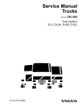
TSI
Volvo Trucks North America, Inc.
Greensboro, NC USA
This TSI Service Bulletin replaces TSI Service Manual
215–003, “Timing Gear Adjustment, D12C” (11.2001),
publication no. PV776–TSP160584.
Date
Group
No.
10.2003
215 003
Supp.
Page
1(11)
Timing Gear Adjustment
D12C
Timing Gear Adjustment
W2003244
Fig. 1: VOLVO D12C Engine
This information covers procedures for checking and adjusting the timing gear on
Volvo D12C engines.
Contents
• “Special Tools” page 2
• “Timing Gear Clearance, Checking (All)” page 3
• “Timing Gear, Adjustment” page 5
PV776-TSP195612
USA14186
Volvo Trucks North America, Inc.
TSI
Date
Group
No.
Page
10.2003
215
003
2(11)
Tools
Special Tools
The following special tools are used to replace or repair components. The tools can be
ordered from Volvo. Please use the specified part number when ordering.
W0001774
9996956
Flywheel Turning Tool
W0001814
W0001979
J-44514-25
J-44935
Camshaft Alignment Tool
(includes J-44426–1, Pointer Tool)
Timing Gear Lash Setting Tool
(Use with J-44514–25)
Volvo Trucks North America, Inc.
TSI
Date
Group
No.
Page
10.2003
215
003
3(11)
Service Procedures
2153-06-03-01
Timing Gear Clearance, Checking (All)
You must read and understand the precautions and
guidelines in Service Information, Group 20, "General
Safety Practices, Engine" before performing this
procedure. If you are not properly trained and certified
in this procedure, ask your supervisor for training
before you perform it.
Volvo Trucks North America, Inc.
TSI
Date
Group
No.
Page
10.2003
215
003
4(11)
1
T2007105
Fig. 2: Axial clearance
T2007104
Fig. 3: Radial clearance
Clearances for the timing gears are:
•
•
•
T2007103
Fig. 4: Backlash
Axial: 0.05 – 0.17 mm (0.002 – 0.007 in.).
Radial: 0.026 – 0.070 mm (0.001 – 0.003 in.).
Backlash: 0.05 – 0.17 mm (0.002 – 0.007 in.).
Volvo Trucks North America, Inc.
TSI
Date
Group
No.
Page
10.2003
215
003
5(11)
2153-05-05-01
Timing Gear, Adjustment
(Timing Gear Backlash)
You must read and understand the precautions and
guidelines in Service Information, Group 20, "General
Safety Practices, Engine" before performing this
procedure. If you are not properly trained and certified
in this procedure, ask your supervisor for training
before you perform it.
Special tools: 9996956, J–44514–25
1
Using flywheel turning tool 9996956, rotate the flywheel
(in normal direction of rotation) until the 0 mark on the
flywheel aligns with the pointer on the flywheel housing.
9996956
C2000183
2
Remove the flywheel turning tool 9996956.
9996956
3
Install the camshaft without the camshaft vibration
damper or gear installed at this time.
Note: Do not install the rocker lever assemblies at this
time. Rocker lever assemblies will be installed after all
crankshaft-to-camshaft timing and front gear backlash
procedures are complete.
4
Rotate the camshaft by hand until TDC mark is aligned
with the left hash mark on the #1 camshaft bearing cap.
Note: The adjustable idler gear bolts are single-use
“stretch” type and must not be reused. However, the
original bolts are used at this time to perform this
adjustment procedure and should be replaced with new
bolts after this procedure is completed (one bolt at a time).
Volvo Trucks North America, Inc.
TSI
Date
Group
No.
Page
10.2003
215
003
6(11)
5
With the adjustable idler gear bolts finger tight, raise the
gear by hand and place a 0.1 mm (0.004 in.) feeler gauge
on the loaded side of the adjustable-to-intermediate
idler gear contact area.
W2003488
6
W2003490
While leaving the camshaft TDC mark on the left hash
mark, install the cam gear and timing collar J–44514–25.
Use 2 camshaft vibration damper/cam gear mounting
bolts to hold gear and collar in place.
J–44514–25
W2003489
Volvo Trucks North America, Inc.
TSI
Date
Group
No.
Page
10.2003
215
003
7(11)
7
Place a 0.1 mm (0.004 in.) feeler gauge between the
loaded side of the cam gear to adjustable idler gear
contact area.
W2003491
8
Using light hand pressure, slowly rotate the camgear
clockwise until the camshaft TDC mark is between the
two hash marks.
Note: Check to ensure that the feeler gauge is in
place on the loaded side of the camshaft gear and
the adjustable idler gear.
W2003492
Volvo Trucks North America, Inc.
TSI
Date
Group
No.
Page
10.2003
215
003
8(11)
9
While using light hand pressure to set the gear last, the
camshaft timing mark should line up between the two
hash marks on the #1 camshaft cap.
W2003493
10
Using special pointer tool J–44426–1, verify that the
camshaft is properly aligned by installing the pointer in
the dowel below the camgear.
J–44426–1
W2003518
Volvo Trucks North America, Inc.
TSI
Date
Group
No.
Page
10.2003
215
003
9(11)
11
Tighten the adjustable idler gear bolts; do not apply final
torque, as these bolts must be replaced with new ones
when all of the adjustments are made to the adjustable
idler gear.
W2003519
12
Remove both feeler gauges.
Note: Slight resistance should be felt as the feeler
gauges are removed.
13
Set up a dial indicator on the adjustable idler gear.
W2003495
Volvo Trucks North America, Inc.
TSI
Date
Group
No.
10.2003
215
003
Page
10(11)
14
Use a pry bar or long screwdriver to hold the intermediate
idler gear in place. Measure the gearlash between the
intermediate-to-adjustable idler gears by rocking the
adjustable idler gear back and forth. Acceptable gear
backlash is between 0.05 – 0.17 mm (0.002 – 0.007 in.).
0.05 – 0.17 mm (0.002 – 0.007 in.)
W2003496
15
Set up a dial indicator on the camshaft gear; use a pry
bar or long screwdriver to hold the adjustable idler
gear in place.
W2003497
16
Measure the gearlash between the camshaft gear and
the adjustable idler gear by rocking the camshaft gear
back and forth. Acceptable gear backlash is between
0.05 – 0.17 mm (0.002 – 0.007 in.).
Note: If either backlash is out of specification, the
adjustable idler gear must be readjusted by repeating
the above steps.
0.05 – 0.17 mm
(0.002 – 0.007 in.)
W2003498
Volvo Trucks North America, Inc.
TSI
Date
Group
No.
10.2003
215
003
Page
11(11)
17
Using timing pointer J–44426–1, again verify that the
pointer will align with the groove in the timing collar.
Note: If the pointer does not align with the groove in the
timing collar, the adjustable idler gear must be readjusted.
J–44426–1
18
Remove all service tools.
19
Replace adjustable idler gear bolts (one at a time) with
new bolts; tighten the new bolts to 15 Nm (11 ft-lb) +
120 . Visually inspect the camshaft and verify that the
camshaft TDC mark is between the two hash marks.
Note: After base engine timing and gear backlash
adjustments are complete, the adjustable timing idler
gear bolts should be replaced and torqued one bolt at a
time to maintain backlash adjustment.
15 Nm (11 ft-lb) + 120
W2003493
20
Remove the cam gear alignment collar.
21
Reinstall camshaft vibration damper. Tighten bolts to a
torque of 33 Nm (24 ft-lb) + 90 .
33 Nm (24 ft-lb) + 90
22
Complete engine assembly according to appropriate
service information.