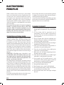
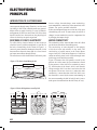
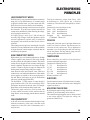
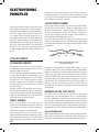
1
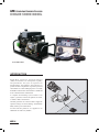
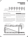
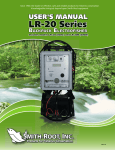
GPP: Generator Powered pulsator
KOHLER shore model
Electrofisher
Control Panel
2!.'%
4)-%).3%#/.$3
%,%#42/&)3(%2
/54054#522%.4
-/$%
%-%2'%.#93(54$/7.
,/7
()'(
!#
/&&
$#
-/$%,'00%,%#42/&)3(%2
-%$)5-
$#
0%2#%.4!'%/&
()'(
%.5-#)!4/26/,5-%
2!.'%
$#
!#
3-)4(2//4).#
6!.#/56%27!
/&&
3%2)!,./
$# $#
$#
05,3%30%23%#/.$
()'(6/,4!'%).$
-/$%
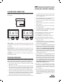
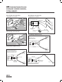
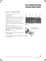
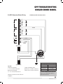
ELECTROFISHER CONTROLS
1 - RANGE: Selects the output voltage range between high and low or switches the output to OFF.
2 - TIME IN SECONDS: Records the actual shocking time. It counts only when high voltage is applied.
3 - EMERGENCY SHUTDOWN: provides a local override of remote foot switches.
4 - OUTPUT CURRENT: this meter shows the current flowing between the anode and cathode in amps.
5 - MODE: Selects the type of output pulses, AC, DC or OFF (Caution!: The position of this switch should not be changed when current is flowing i.e. foot switches engaged!).
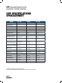
6 - LOW RANGE: Indicates that the RANGE switch should be moved to the LOW position. For 7.5 and 9.0 GPPs, follow the output table. Damage to the range selector switch may result from switching under load.
7 - PERCENT OF RANGE: Adjusts the output pulses to a percent of the selected range, i.e. high/low. Pulse width is also automatically adjusted between 6 and 1 millisecond pulse duration.
8 - HIGH VOLTAGE: Red indicator lamp shows when voltage is present on output power terminals.
9 - PULSES PER SECOND: Selects the number of pulses in the output wave form.
GPP-
2006