1
electrofishing
principles
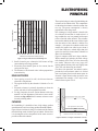
Voltage across fish
6.25
Field Intensity, V/cm 6.25
Distance from anode, m 1.2
9.5
18
30
50
280
12.5
22
40
70
120
400
1.0
0.8
0.6
0.4
0.2
0.0
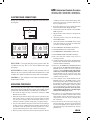
As the fish nears the anode it receives a very high head-to-tail voltage.
Zone of Potential Fish Injury
Electrode Design
Fish close to the anode receive a very high head-to-tail voltage. Most
fish injuries occur within half a meter from the anode. This is called
the Zone of potential fish injury. We can minimize the injury by
reducing the time the electricity is turned on .
Duty-Cycle
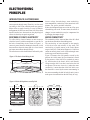
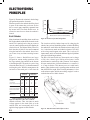
The way in which voltage and current distribute
around electrofisher electrodes is complex. Figure 4
shows the field pattern created by a pair of closely
spaced ring electrodes, and the voltage gradient
between them. Note that the current density and
voltage gradient are highest near the electrodes.
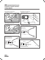
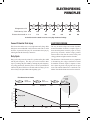
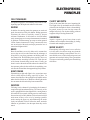
Duty-cycle is the percent of on-time. It is a product of the pulse width
and the pulse frequency. The duty-cycle can be lowered in three
ways: by reducing the pulse width, by reducing the pulse frequency,
or by using gated bursts, where the power is off for a period between
each burst of pulses. Fish close to an anode with a low duty-cycle are
far less likely to be injured than with a high duty-cycle.
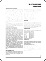
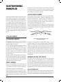
The dimensions of the electrodes are very important
in determining the voltage distribution around
electrofisher electrodes. Figure 5 compares a 10cm
and a 20cm ring anode carrying 200 volts in open
water. The cathode dimension is considered to be
infinite. Note that the 20cm anode reaches out much
Fish Attraction to Anode
Limited
Galvanotaxis
3.0m
Zone of
Potential
Injury
Good
Galvanotaxis
2.0m
DISTANCE
1.0m
0.5m
60
40
Duty Cycle
Anode
DUTY CYCLE %
50
30
20
10
0
0
2
4
6
Varying Width Pulses
ON
2006
OFF
Varying Frequency Pulses
ON
TIME
8
10
12
14
18
www.smith-root.com