1
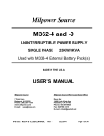
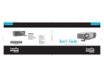
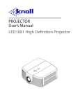
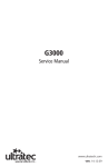
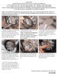
Section
5-5
Filter Service
Effective filtration of fluids is vital to the longevity and
performance of your Wagner. See the previous section
on Preventive Maintenance for the scheduled intervals
for filter element replacement where applicable.
Some filter elements (the Air Cleaner elements, for
example) do not have an established service interval,
but must be changed based on need. Variations in
environmental conditions result in different servicing
requirements.
See Figure 5-5-1 for the location of the filters on your
machine. Refer to the parts manual or suggested
stocking guide (SSG) for your machine for part numbers of filter elements. You should always have a full
set of replacement elements in stock for your machine.
Contact your dealer for details.
Refer to the following pages for timing and procedures
of filter element replacement.
WARNING
Lubricating oils are extremely hot while the
machine is running, and may cause severe
burns or death upon contact. Shut down the
machine, employ lockout/tagout procedures,
allow the machine to cool and wear appropriate
personal protective equipment when changing
fluids or filter elements.
Cab Air
Recirculation Elements
Cab Pressurizer
Air Filter
Return Filters
Transmission Filters
Engine Filters
. Fuel Filter
. Coolant Filter
. Oil Filter
High Pressure
Hydraulic Filters
Figure 5-5-1 Filter Arrangement
94-1507-01 Rev: 5-2014
5-5-1
Service Instructions
High Pressure Filters
Service Interval: Quarterly, every 500 hours, or when
indicators dictate, whichever occurs first.
Indicators for the high pressure filters are located in
the cab (amber overhead lights) and on the filters in
the service bay. See Section 5-4-1 for details.
Allow the machine to warm up. If, after the hydraulic oil
is warm, any indicator lights in the cab remain illuminated, or if any indicator on a filter (item 8 below) returns to red after being reset, the filter element(s) must
be changed before returning the machine to work,
even if prior to the quarterly/500 hour interval.
1. Stop system power and vent captive pressure.
2. Drain filter assembly.
3. Remove bowl and element assembly.
4. Push down to squeeze tangs and lift element (see
Figure 5-5-3).
Tangs
8
1
Figure 5-5-3
2
3
5. Twist to remove core (see Figure 5-5-4).
4
5
6
7
1.
2.
3.
4.
Filter Head
Element
Core
O-Ring, Bowl
5.
6.
7.
8.
O-Ring, Anti-Extrusion Ring
Bowl
Plug, Drain
Filter Indicator
Figure 5-5-2 Parts Identification
5-5-2
Figure 5-5-4
94-1507-01
Rev: 5-2014
6. Retain reusable core (see Figure 5-5-5).
Figure 5-5-5
9. Push element assembly into bowl until tangs snap
(see Figure 5-5-7).
Figure 5-5-7
7. Discard used element.
10. Inspect o-ring and anti-extrusion ring.
8. Insert reusable core into new element (see Figure
5-5-6).
11. Install bowl with new element (see Figure 5-5-8).
12. Torque bowl (25-30 ft-lb/35-40 N-m) and drain plug
(25-30 ft-lb/35-40 N-m).
13. Power up and inspect.
Figure 5-5-6
94-1507-01 Rev: 5-2014
Figure 5-5-8
5-5-3
Return Filters
Service Interval: Quarterly, every 500 hours, or when
the indicator dictates, whichever occurs first.
The return filters are accessed from the deck on the
right side of the machine. See Figure 5-5-9. The indicator for the return filters located in the Right Side Service Bay next to the sight gauge. See Figure 5-5-10.
Allow the machine to warm up. If, after the hydraulic oil
is warm, the plunger on the indicator is in the red zone,
both filter elements must be changed before returning
the machine to work, even if prior to the quarterly/500
hour interval.
The differential pressure indicator in Figure 5-5-10 indicates the elements are in working condition. As the
elements collect contamination, the indicator plunger
will rise into the red zone, indicating that the elements
must be replaced.
Return Filters
Breather
Petcock
Figure 5-5-9 Return Filters
5-5-4
Figure 5-5-10 Differential Pressure Indicator
94-1507-01
Rev: 5-2014
Replacing the Filter Elements
1. Shut down the machine and vent captive pressure
by opening the petcock at the breather. See
Figure 5-5-9.
2. Clean cover plate and surrounding area.
3. Remove cover plate and gasket.
4. Remove in-tank filter assemblies.
1
5. Remove the bypass spring assembly (see
Figure 5-5-11).
6. Remove contaminated cartridge with a twisting
motion.
7. a. Discard disposable element.
b. Wash sleeve in non-caustic solvent. Compressed air can be used to prevent damage to the
element during cleaning.
Magnetic
Core
2
Bridge
Stud
3
Before Installing Cartridge
1. Clean magnetic core (insert assembly) with a lint
free cloth.
4
2. Check all seals and tank cover gasket and replace
if necessary.
To Assemble and Install New or Cleaned
Cartridge
1. Lubricate all seals
Cartridge
5
2. Insert new element into clean sleeve.
3. Assemble insert assembly and cartridge.
Note: For ease of mounting, hold the cartridge
away from the magnetic core until the stud is
through the hole in the bottom of the cartridge.
Then slide the cartridge up to securely seat with
the top of the bridge of the insert assembly.
6
4. Install bypass spring assembly or non-bypass
plate (tighten until snug).
5. Reinstall in-tank return filter into housing (make
sure the top spring is secure).
6. Reinstall cover. Torque cover nuts (see 80-1057
Torque Specification Chart).
1. Spring, Top
2. Insert Assembly
3. O-Ring(Insert to Tank)
4. Element
5. Sleeve
6. Bypass Spring Assy
7. Close the petcock.
Figure 5-5-11 Return Filter Assembly
94-1507-01 Rev: 5-2014
5-5-5
Engine Filters
Engine Filters include the engine oil filter, the coolant
filter, and the fuel filter. All are located in the Right Side
service bay. See Figure 5-5-12.
Service Intervals:
Fuel and Coolant Filters: Monthly, every 250 hours,
or as dictated by a fault code, whichever occurs first.
Engine Oil Filters: Quarterly, every 500 hours, or as
dictated by a fault code, whichever occurs first.
Fuel Filter
The normal service intervals will be sufficient in most
cases. Occasionally, the engine may throw a fault code
indicating that a filter element needs to be replaced
sooner. The filter element must be replaced prior to
returning the machine to work, even if prior to the
scheduled interval.
Refer to Section 2 of your Wagner Service Manual for
the fault codes for your machine.
Refer to the Operation and Maintenance Manual supplied with your engine for filter change procedures.
Coolant Filter
Engine Oil Filter
Figure 5-5-12 Engine Filters
5-5-6
94-1507-01
Rev: 5-2014
Service Instructions
Transmission Filters
The transmission filters are located in the Right Side
service bay. See Figure 5-5-13.
Service Interval: Quarterly or every 500 hours, whichever occurs first.
1. Shut down the machine.
2. Clean the area around the filter elements before
removing.
3. Using a filter wrench, remove the transmission
filter elements and discard.
4. Clean the mating surface of the filter head before
installing the new filter elements.
5. Using a filter wrench, install the new transmission
filter elements.
Transmission Filters
Figure 5-5-13 Transmission Filters
94-1507-01 Rev: 5-2014
5-5-7
Air Cleaner
Service Interval: When indicator dictates.
Variations in environmental conditions do not allow for
any set interval to be established for replacement of
the air cleaner elements. Obviously, dustier environments will require more frequent element changes.
Therefore, the indicator must be used to determine
when it’s time to replace the elements. This indicator, mounted between the air cleaner housing and the
machine’s cab (see Figure 5-5-14), must be checked
at least once per shift, and the elements replaced as
necessary.
General
The air cleaner is critical to the life of the engine. It
prevents dust and debris from entering the engine air
system, causing premature engine wear and possible
failure. When a two stage, dry type air cleaner is used,
air passes through the outer, primary filter elements
installed; both are required to fully protect the engine
from contamination.
Air Filter Service Indicator
This gauge indicates filter element condition without
filter disassembly. The service sight gauge indicates
filter contamination by showing “red” or “green” in the
sight gauge. The visible amount of red on the indicator
will increase as the dust in the element increases.
For maximum engine performance, the filter should be
changed or cleaned immediately after the “red” signal
locks in full view.
To reset the service gauge, press the button on the top
of the gauge.
Air Cleaner Connections
Check the intake tubes between the air cleaner outlet
and the turbocharger for cracks or wear, and that all
clamps are in place and are tight.
Replace any worn or damaged tubes and tighten any
loose clamps.
Service Instructions
1. Shut off engine. Unlatch and remove the housing
service cover.
Indicator
Figure 5-5-15
Figure 5-5-14 Air Cleaner Indicator
5-5-8
94-1507-01
Rev: 5-2014
2. Using the handle, push down on the primary filter
to loosen the seal, which will tilt the filter to approximately a 5° angle. Pull the filter out of housing.
NOTE: Remove any excess dirt and wipe out
the housing before removing the safety (or
secondary) filter.
5. If replacing safety/secondary filter, use the plastic handle on the safety filter, slide the filter at an
angle into the outlet side and push in place until
the filter seats firmly and evenly within the housing.
NOTE: insert the safety filter tab into the positioning slot before pushing the filter in place.
Safety Filter
Positioning Tab Location
Figure 5-5-19
Figure 5-5-16
3. Using the plastic handle on the face of the safety
filter, pull the filter toward the center of the housing
and remove.
6. Slide the filter down at approximately a 5° angle
until it hits the end of the housing. Rotate the filter
toward the outlet section to complete the seal.
NOTE: A safety/secondary filter only needs
to be replaced at every third primary air filter
change.
Plastic
Handle
Figure 5-5-20
7. Place the service cover in position and fasten the
latches.
Figure 5-5-17
4. Inspect the new filter before installing. Visually
check for cuts, tears, or indentations on the sealing
surfaces before installation. If any damage is visible, do not install.
Figure 5-5-21
Figure 5-5-18
94-1507-01 Rev: 5-2014
5-5-9
Cab Air Recirculation Elements
Cab Pressurizer Filter Element
The cab air recirculation elements are located in the
cab, under the dash. See Figure 5-5-22.
The cab pressurizer is mounted to the back of the cab.
See Figure 5-5-23.
Service Interval: Semi-annually, every 1,000 hours, or
when the cab pressurizer element is replaced, whichever occurs first.
Service Interval: Semi-annually, every 1,000 hours, or
when a noticeable drop in cab pressure occurs, whichever occurs first.
Service Instructions
Service Instructions
1. Shut down the machine.
1. Disconnect flex hose from air outlet. Plug or cover
end of hose to prevent contaminants from entering
the HVAC system.
2. Remove the covers.
3. Remove and discard the elements.
4. Clean the filter mounting areas.
5. Install new filter elements.
6. Install the covers.
2. Unlatch the six clips which hold the lid in place.
3. Once the lid is removed, examine the rubber
gasket that seals the lid to the filter housing. If the
rubber gasket is torn or missing replace it.
Filter Elements
Figure 5-5-22 Cab Air Recirculation Elements
5-5-10
Figure 5-5-23 Cab Pressurizer
94-1507-01
Rev: 5-2014
4. Remove the filter retention clip by (1) pressing clip
towards the filter’s outer ring, then by (2) lifting the
clip out by pulling up on tab. DO NOT DISCARD
THE CLIP! You will need this clip to reinstall the
new filter.
9. Reinstall filter retention clip by pushing filter retention clip into place. Clip will snap and lock into
place.
Figure 5-5-25
Figure 5-5-24
5. Remove the filter by applying pressure in a motion away from the outlet of the filter box. The filter
is held firmly by the rubber “O” ring seal and will
require gentle but firm pressure to remove.
6. Bag and seal used filter element and dispose of
according to local regulation.
7. Remove loose debris using suitable vacuum unit
and clean rags - never use compressed air.
8. Lubricate O-ring seal on filter element (lubricant
provided with new filter). Place in housing with
open end of filter towards outlet, lift slightly with
fingers to align with inside of outlet and shift
towards outlet until you feel positive abutment and
the O-ring seats into the groove inside the outlet.
94-1507-01 Rev: 5-2014
10. Replace the lid.
11. Latch the six lid clips to seal unit
12. Reattach the flex hose to the outlet, ensuring that
contamination of tubing, HVAC, and cabin air does
not occur. Take care not to overtighten clamps, as
this could cause “crush” damage.
CAUTION
Do not clean or reuse filter elements. Replace
with new elements only. Reusing filter elements may create a health hazard.
5-5-11
INTENTIONALLY LEFT BLANK
5-5-12
94-1507-01
Rev: 5-2014