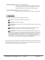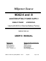
1
Milpower Source M362-4 and -9 UNINTERRUPTIBLE POWER SUPPLY SINGLE PHASE 2.5KW/3KVA Used with M333-4 External Battery Pack(s) MADE IN THE U.S.A USER’S MANUAL Milpower Source Milpower Source West Coast Sales Office 7 Field Lane Belmont, NH 03220 Phone: (603) 267-7355 www.milpower.com E-mail: [email protected] Dave Hall 1498 Linda Vista Ave. Pasadena, CA 91103 Phone: 626-304-9620 Fax: 626-796-1415 E-mail: [email protected] MPS Doc: M362-4 & -9_USER_MANUAL Rev B July 2014 Page 1 of 34 Table of Contents Para 1 1.1 1.2 2 3 3.1 3.2 4 5 5.1 5.2 5.3 5.4 5.5 5.6 5.7 5.8 5.9 6 6.1 6.2 7 7.1 7.2 7.3 8 8.1 8.2 9 Description Page Important Safety Instructions General Description Intended Application Overview Electrical Installation Instructions Power Connectors and Pin Out Signal Connectors and Pin Out Front Panel Description Front panel: Main Components Front Panel: Indicators and Controls Rear Panel Description Operating the M362 Quick Start – turning the M362 On and OFF Front Panel and Remote Switches Description Operating Modes Automatic Transfer to By-pass Mode Visual Indicators and Push-buttons Battery Tests UPS Response to Input AC Failure UPS Response to Overload Condition UPS Response to Over Temperature Condition Maintaining the M362 Replacing the Battery Pack Air Filters Maintenance Communication and Remote Control Discrete Signals Interface Remote Control Switches RS-232 Serial Interface Theory of Operation Power Conditioner UPS Section Specifications MPS Doc: M362-4 &- 9_USER_MANUAL Rev B July 2014 3 4 4 4 6 7 8 9 9 10 11 12 12 12 13 14 15 17 18 18 21 22 22 23 25 25 26 27 28 28 29 32 Page 2 of 34 IMPORTANT SAFETY INSTRUCTIONS The M362 UPS and the M333-4 Battery Pack should not be tampered with by unauthorized personnel. Tampering with these units or using any of them in any other way but the intended application, may result in a safety hazard. The M362 should be used only with Milpower’s M333-4 Battery Pack(s). Connecting the M362 to any other battery may damage the M362 and may result in a safety hazard. Disconnecting the input connector does not turn off the UPS. The M362 should only be plugged into an approved, double-pole circuit breaker (C.B.) or a fused electrical outlet, rated for 32 to 42Amp for M362-4 and 10 to 15Amp for M362-9. When the M333-4 is energized, high voltage may appear on the pins of connector J2 on the back panel of the M333-4. Verify that connector J2 on the M333-4 is never left open. If J2 is unused, seal it with its Connector Cup. For proper mechanical support in installation that should withstand high impact shocks or vibration: Use at least three bolts on each side of the front panel. Do not rely on the slides for mechanical support. Use the two pins (supplied with the unit) and bushings on the rear of the unit. MPS Doc: M362-4 &- 9_USER_MANUAL Rev B July 2014 Page 3 of 34 1. General Description 1.1. Intended Applications The M362 is a high quality, rugged, 2.5KW/3KVA, 19” rack-mounted, Uninterruptible Power Supply (UPS) that uses external Power Pack(s) and able to provide very long holdup times. The M362 fully complies with all the requirements of MIL-STD-1399-300B and is specifically designed to meet harsh military shipboard environment. The high reliability and ruggedness of the M362 make it an excellent choice not only for military shipboard applications, but for critical shore-based applications as well. 1.2. Overview 1.2.1. AC Input and AC Outputs The M362-4 is fed from a single phase 115VAC/60 source (can be configured by the user to 230VAC/50-60Hz by using the Input Voltage Range Selector on the top cover of the M362). The M362-9 is fed from a 440VAC/60Hz source. Both the -4 and the -9 provide two uninterrupted 115VAC/60Hz low-distortions sine-wave outputs. One output (AC-1) is rated to the full UPS rating (3KVA) and the other (AC-2) is rated at 1.1KVA (10Arms). Total output power is limited to 2.5KW/3KVA. The two outputs are fed from the same internal source (a common DC-AC Inverter) and share a common Neutral line (isolated from AC Input). AC-2 is intended to feed non-essential loads and in case of an AC Input failure that lasts for more than 14 seconds, the M362 automatically disconnects AC-2 and reserves the battery power for AC-1. 1.2.2. Isolation between AC Input to AC Outputs The AC outputs of the M362 are completely isolated and independent of any fluctuations and disturbances on the AC Input. The same is true in the opposite direction; in UPS Mode the M362 isolates the Primary source (shipboard power) from disturbances and EMI interferences generated by the AC loads. In case of an interruption on the AC Input, the transition from AC Power to Battery power (and backward when the AC Input recovers) is seamless and the AC outputs remain undisturbed. The UPS section of the M362 provides failure isolation between the loads on its output to the Prime source (Shipboard Power). Overloading, or even applying a full short the M362 outputs, will not result in overloading of the Shipboard Power. For safety reasons, the Neutral of the AC Outputs is shorted to Chassis Ground internal to the M362. If the application dictates that the grounding point of the Neutral should be external to the source (the M362) this Ground Connection can be removed by the user. Note: The grounding of the AC Output is essential and does not violate MIL-STD-1399-300B that applies only to shipboard power (that is galvanically isolated from the AC Output of the M362 and is not affected by the grounding). MPS Doc: M362-4 &- 9_USER_MANUAL Rev B July 2014 Page 4 of 34 1.2.3. Battery The M362 does not have an internal battery, and relies on external Battery Pack(s) (Milpower’s M333-4). Up to four Battery Packs can be connected to the M362. The M362 automatically identifies the type and the number of Battery Packs that are connected to it and adjusts its internal parameters accordingly. 1.2.4. By-Pass Figure 1 below shows the main building blocks of the M362. When the M362 operates in UPS (Normal) mode, the Input and Output relays are closed, and the By-pass relay is open. When the M362 goes to By-pass mode, the Input and Output relays open (disconnecting all of the active circuits of the M362) and the By-pass relay closes, connecting the AC Outputs directly to the output of the passive Power Conditioner. In the By-pass mode, the load current is limited by the external (user provided) circuit breaker on the AC outlet that feeds the M362. Note: The Power Conditioner contains internal fuses on its input lines (AC In 1 and AC In 2 on Figure 1 below). These internal fuses are intended only as an additional safety feature and should not be considered or used as the main overload protection devices. During normal (UPS) mode operation, the current through these fuses is much lower than the 60Amp (for -4) rating of the fuses (20Amp for -9) regardless of the load on the M362 output. In the unlikely event that these fuses open, it may indicate the existence of an internal safety hazard and the M362 should be returned to the manufacturer for inspection/service. These internal fuses should never be replaced without through testing of the M362. Bypass Relay AC-2 Relay AC In (1) AC In (2) Power Conditioner (Isolation XFMR & Filters) Output Relay Input Relay UPS Section AC-2 Out AC-1 Out Neut Out Figure 1: M362 Main Blocks Diagram MPS Doc: M362-4 &- 9_USER_MANUAL Rev B July 2014 Page 5 of 34 2. Electrical Installation Instructions Before installing the unit, please read carefully the Safety Instructions at the beginning of this manual. Before connecting the M362 to the AC Input source verify the followings: Verify that the cables that will interface with the UPS are properly wired (Tables 2-1, 2-2 and 2-7 for Power connections and Tables 2-3, 2-4 and 2-5 for signals connections). Verify that the electrical outlet that powers the UPS is a single phase, 60Hz, of the right line-to-line voltage (115VAC or 230VAC for the M362-4 and 440VAC for the -9). For the -4 only: verify that the 115/230VAC AC Range Selector on the top cover of the M362 is set to the right range. Verify that the outlet that provides the input power is protected by a double-pole circuit breaker (or fuses) rated to: 32 to 42Amp for 115VAC input, 16 to 25Amp for 230VAC input and 10 to 15Amp for 440VAC input. The UPS Chassis is grounded to the rack by the GND connection on the back-panel of the UPS. The GND conductor should be AWG #8 or thicker. (For best EMI performance use a wide and short low-inductance braid). Verify that the External Battery Pack(s) is properly installed (Per the M333-4 User’s Manual). Verify that the circuit breaker on the outlet that feeds the UPS is off. Make sure that all the switches on the M362 front panel are in the OFF position. Connect the AC cable coming from the input source to the Input Connector J1. Connect the AC cable that feeds your equipment to the Output Connector J2. Connect the Battery cable (from the External Battery Pack) to J7 Connect the monitoring and control cables from the host computer to the appropriate connectors on the UPS back panel. If the Remote Switches are not used, verify that a mating connector is plugged into J4 (on the rear panel of the Unit) and that it has two jumpers, one between Pin 8 to Pin 5 and a second jumper between pin 6 to pin 4. Turn on the 115VAC circuit-breaker that provides power to the outlet that feeds the M362. The M362 is now ready for operation (see Paragraph 5). MPS Doc: M362-4 &- 9_USER_MANUAL Rev B July 2014 Page 6 of 34 M362 Power Connectors Designation and Pin Out Table 2-1 Table 2-2 J1 – AC Input MS3452L20-22P or Eq. J2 – AC Output MS3452L20-22S or Eq A GND AWG #8 A GND B N/C AWG#16 B C AC-IN(1) AWG #8 C D N/C AWG#16 D GND AWG#16 E AC-IN(2) AWG #8 E 115VAC-1 AWG #8 F N/C AWG#16 F 115VAC-2 AWG#16 115VAC-2 (NEUT) 115VAC-1 (NEUT) AWG #8 AWG#16 AWG #8 Table 2-7 J7 – Battery MS3452L20-27S or Eq A GND AWG #16 H BATT-RTN AWG #16 B IDRES-2 AWG #16 I BATT-RTN AWG #16 C TMPSNS-1 AWG #16 J RESERVED AWG #16 D TMPSNS-2 AWG #16 K 24VDCRTN AWG #16 E +BATT AWG #16 L IDRES-1 AWG #16 F +BATT AWG #16 M +BATT AWG #16 G +24VDC AWG #16 N BATT-RTN AWG #16 Notes: 1) The Connectors P/N shown above are of the M362’s connectors (not the mating connectors). 2) The 115VAC-1 (NEUT) and the 115VAC-2 (NEUT) are the Neutrals of the AC outputs. They are tight together and to Chassis GND in the M362. 3) The GND Lines on J1 and J2 are Safety Ground. In addition to tying these pins to the proper GND at the far side of the cables, the M362 GND Point (on the rear panel) must be grounded to the Host Rack using #8 wire (as short as practical) or (preferably) a low-inductance braid rated to 30Amp or higher. 4) For proper operation of the Battery Pack, all Pins of J7 must be connected. MPS Doc: M362-4 &- 9_USER_MANUAL Rev B July 2014 Page 7 of 34 M362 Signal Connectors Designation and Pin Out Table 2-3 J3 – Discrete Signals D-Type 25 Female 1 BTL_MOD_CMD AWG#20 14 BTL_MOD_CMD_ RTN AWG#20 2 3 4 5 6 7 8 9 10 11 12 13 N.C. RMT_SW_RTN RMT_SW_RTN RMT_PWR_ON_SW N.C. RS232_RTN RESERVED RESERVED N.C. OUTPUT_OK_SIG N.C. ON_BATT_SIG AWG#20 AWG#20 AWG#20 AWG#20 AWG#20 AWG#20 AWG#20 AWG#20 AWG#20 AWG#20 AWG#20 AWG#20 15 16 17 18 19 20 21 22 23 24 25 N.C. RMT_SW_RTN RESERVED RMT_UPS/BYPASS_SW N.C. RS232_TXD RS232_RXD N.C. O_TEMP_SIG SIG_RTN LOW_BATT_SIG AWG#20 AWG#20 AWG#20 AWG#20 AWG#20 AWG#20 AWG#20 AWG#20 AWG#20 AWG#20 AWG#20 Table 2-4 J4 – Remote ON/OFF D-Type 15 Female Table 2-5 J5 – RS-232 D-Type 9 Female 1 N/C AWG #20 1 N.C. AWG #20 2 3 4 5 6 7 8 9 10 11 12 13 14 15 1 N/C RMT_SW_RTN RMT_SW_RTN RMT_SW_RTN RMT_UPS/BYPASS_SW RESERVED RMT_PWR_ON_SW N/C N/C N/C N/C N/C N/C N/C N/C AWG #20 AWG #20 AWG #20 AWG #20 AWG #20 AWG #20 AWG #20 AWG #20 AWG #20 AWG #20 AWG #20 AWG #20 AWG #20 AWG #20 AWG #20 2 3 4 5 6 7 8 9 RS232_TXD RS232_RXD N.C. RS232_RTN N/C RESERVED RESERVED N/C AWG #20 AWG #20 AWG #20 AWG #20 AWG #20 AWG #20 AWG #20 AWG #20 Notes: 1) The Connectors’ P/N shown above are of the M362’s connectors (not the mating connectors). 2) If Remote Switches are not used, short pins 8 of J4 to pin 5, and pins 6 of J4 to pin 4. 3) When interfacing with J5 use “straight” 9-pins RS232 cable. 4) Signals of the same name that appear in several connectors are the same signal, provided in more than one connector in order to facilitate convenient cabling. Do not use more than one instance of each signal. MPS Doc: M362-4 &- 9_USER_MANUAL Rev B July 2014 Page 8 of 34 3. Front Panel Description Note: Except for the Dash (-#) number and description, the front and rear panels of the M362-3 -4 and -9 are identical (Figures 2, 3 and 4 are of the M362-3). 3.1. Front Panel: Main Components (Figure 2) 1. 2. 3. 4. 5. 6. 7. 8. Left Handle. “Small” Air-filter Cover. Visual Indicators and Controls (for detailed view see Figure 4) Power On/Off Switch. Input On/Off switch. Output On/Off switch. “Large” Air-filter Cover. Right Handle. 1 2 3 4 5 6 7 8 Figure 2: Front Panel View MPS Doc: M362-4 &- 9_USER_MANUAL Rev B July 2014 Page 9 of 34 3.2. Front Panel: Indicators and Controls (Figure 3) 13. 14. 15. 16. 17. 18. 19. 20. 21. 22. 23. 24. 25. 26. 27. 28. 29. Load Level Bar Graph (marked in %, 100% = 2.5KW). Output Stand-by LED (Yellow). Input Fail LED (Red). Input OK LED (Green). Output OK LED (Green. By-Pass LED (Yellow). Output Fail LED (Red). On Batt Warning LED (blinking Yellow). Alarm Off Push-button. Used also to Reset Batt Charge Level. Low Batt Warning LED (blinking Yellow). Overload Shutdown LED (Red). Over Temperature (blinking Red). Battle Mode LED (White). Batt Test Fail LED (Red). Batt Test/Safe-to-Remove Push-button. Batt Test Pass LED (Green). Batt Charge Bar Graph (marked in %, 100% = Full Charge). 15 14 16 17 13 18 19 20 21 29 22 23 27 28 26 25 24 Figure 3: Indicator and Controls View MPS Doc: M362-4 &- 9_USER_MANUAL Rev B July 2014 Page 10 of 34 4. Rear Panel Description (Figure 4) 30. 31. 32. 33. 34. 35. 36. 37. 38. Left Side Bushing (mating pins are supplied with the unit). J1, Input Power Connector (see Table 2-1 for type and pin-out). J2, Output Power Connector (see Table 2-2 for type and pin-out). J7, Battery Connector (see Table 2-7 for type and pin-out). Cooling fan (air outlet). J3, Signals Connector (see Table 2-3 for type and pin-out). J4, Remote Switches Connector (see Table 2-4 for type and pin-out). J5, RS-232 Connector (see Table 2-5 for type and pin-out). Right side Bushing (mating pins are supplied with the unit). 39. GND Connection, threaded hole, 10-32 UNF-32, .40 (min) deep. 30 31 32 33 34 35 36 37 39 38 Figure 4: Rear Panel View MPS Doc: M362-4 &- 9_USER_MANUAL Rev B July 2014 Page 11 of 34 5. Operating the M362 5.1. Quick Start - Turning the M362 On and Off The M362 will not turn-on with Battery power only. Therefore, to turn-on the M362, AC Input must be presented at the Input connector J1. When Remote switches are not used: The Input On/Off switch (5) and Output On/Off switch (6) should be in the Up (On) position. Toggling the Power On/Off switch (4) Up turns On the M362 and Down turns it Off. Note: When the remote switches are not used, Pins 5 and 8 of J4 (the Remote SW connector) should be connected to each other. (The M362 is shipped with a mating connector and jumpers already installed on J4.) When the Remote switches are used: All the switches on the front panel of the M362 should be in the upper (On) position. Toggling On the Remote On/Off switch (close position) turns On the M362 and Off (open position) turns Off the M362. 5.2. Front Panel and Remote Switches Description The M362 has three toggle switches (Power On/Off, Input On/Off and Output On/Off) on its front panel. It has inputs for two remote switches (Remote On/Off and Remote UPS/By-pass) on connectors J4 (and J3). PWR On/Off Switch (4): When On; the M362 is enabled. When Off; power is removed from all UPS circuits (regardless of any other switch or signal). Note: the primary of the Isolation Transformer of the Power Conditioner is not affected and remains energized. Input On/Off Switch (5): When On; connects the AC Input to the UPS. When Off; disconnects the AC input from the UPS. If the UPS is Already On, it continued to operate on battery power (Test Mode). Output On/Off Switch (6): When On; enables the AC Output of the UPS. When Off; drives the M362 to Standby Mode (AC Output is Off, but battery charger and all other functions remain functional). MPS Doc: M362-4 &- 9_USER_MANUAL Rev B July 2014 Page 12 of 34 Remote On/Off (J4/8, 5): When shorted; enables the M362. When open; remove power from all circuits (regardless of any other switch or signal). Note: the primary of the Isolation Transformer of the Power Conditioner is not affected and remains energized. Remote UPS/By-pass (J4/6,4): When shorted: enables the UPS. When open; disables the UPS and drives the M362 to By-pass mode. 5.3. Operation Modes The M362 has five (5) operational modes as described below. 5.3.1. Off: All relays are open. The Battery Pack switch is off. 5.3.2. UPS Mode: Normal (UPS) operation. 5.3.3. Standby Mode: AC output is off. The front panel display, charger and communication remain functional. 5.3.4. Test Mode: AC Input relay is open and the M362 operates on battery power. All functions (except for charger) remain functional. (Tests the UPS function). 5.3.5. By-pass Mode: The AC output is connected directly to the Power Conditioner. No UPS function, no charging, no communication and no display (except for the By-pass LED). Allows a degraded performance operation during a UPS hardware failure. Once entering By-pass Mode the M362 will remain latched in it. To exist By-pass Mode, the Power On/Off switch (or the Remote PWR On/Off switch) must be toggled Off and then back On or, AC input power removed and then re-applied. (See also Paragraph 5.4). The Truth Table on the next page specifies the Operation Mode for each setting of the Switches. In the table below Ø denotes “Don’t care”. The symbol → denotes a change of state that occurs when all of the other switches are already in the specified states. MPS Doc: M362-4 &- 9_USER_MANUAL Rev B July 2014 Page 13 of 34 Table 5-1 PWR On/Off Switch Remote Power On/Off Remote UPS/ Bypass Input On/Off Switch Output On/Off Switch OFF Ø Ø Ø Ø Ø Open Ø Ø Ø OFF→ON Close Close ON ON ON Open→Close Close ON ON M362 will turn On into UPS (Normal) Mode. ON Close Close ON OFF Standby Mode (AC Output is Off). ON Close Close ON→OFF ON M362 will enter Test Mode (Operating on Battery Power) OFF→ON Close Ø OFF Ø ON Close Open Ø Ø ON Close Ø OFF OFF M362 Operation Mode The M362 is Off. All relays are open. Latched in By-pass Mode. 5.4. Automatic/Manual Transfer to By-pass Mode When in this mode the Input and Output relays are open (isolating the failed UPS circuits) and the By-pass relay is close, connecting the output of the Power Conditioner directly to the AC Output Connector (see Figure 1 on Page 5). Charger, communication and display functions (except for the By-pass LED) are all disabled. Once entering the By-pass Mode the M362 will remain latched in it. To exist By-pass Mode the Power On/Off switch (or the Remote PWR On/Off switch) must be toggled Off and then back On, or AC input power removed and then reapplied. 5.4.1. Manual Transfer to By-pass The M362 can be manually driven to By-pass mode by turning Off the Front Panel Input and Output switches when the Power On/Off switch is On, or by toggling the Remote UPS/By-pass to By-pass (when the Remote switches are used). 5.4.2. Automatics Transfer to By-pass In case of a UPS failure; the M362 will automatically transfer to By-pass mode within 3 seconds. The automatic transfer will occur only if all of the following conditions are met: 1) Both the PWR On/Off Switch and the Remote On/Off switch are On (or if Remote switches are not used, pins 5 and 8 of J4 are connected). 2) AC Input voltage is available. 3) AC Output is lost for more than 1 second. 4) The cause of the low AC Output is not an Overload condition or user command. MPS Doc: M362-4 &- 9_USER_MANUAL Rev B July 2014 Page 14 of 34 During the first 5 seconds after turn-on, the automatic By-pass is disabled, allowing the M362 to turn-on normally (into UPS Mode). An Overtemp failure of the UPS will drive the M362 to By-pass Mode. 5.5. Visual Indicators and Push-buttons 5.5.1. Input Fail/OK LEDs (15 and 16). Indicate the status of the AC Input into the UPS. If the AC Input is normal, the Green OK LED (16) will be on. If AC Input is not provided (or too low for normal operation), the Red Input Fail LED (15) will be on and the Green Input OK LED (16) will be off. When in the ByPass mode, these two LEDs are off. 5.5.2. Output Fail/OK/STBY LEDs (19, 17 and 14). Indicate the status of the AC Output. When the AC Output is normal, the Green Output OK LED (17) will be on. If the UPS is in Stand-by Mode (AC output disabled), the Yellow Output STBY LED (14) will be on and the Green Output OK LED (17) will be off. If the AC Output is not available (because of an external over-load or any other failure) the Red Output Fail LED (19) will be on. When in the By-Pass mode, these three LEDs are all off. 5.5.3. On Batt Warning LED (20) When the M362 is using Battery power, the Yellow On Batt Warning LED (20) will start blinking, warning the user that the UPS is working on Battery power. 5.5.4. Low Batt Warning LED (22) When the Battery Charge level is below 35%, the Yellow Low Batt Warning LED (22) will blink, warning the user that the Battery Level is low. The above it true even when the Battery is charged by the M362. 5.5.5. Over Load Shutdown LED (23). If the AC Output of the M362 has shut down due to a short circuit or an overload condition on the Output, the Red Over Load Shutdown LED (23) will turn on, indicating to the user that the shutdown was due to an overload condition. 5.5.6. Over Temperature LED (24) In case of an Over Temperature of the M362 the Yellow Over Temperature LED (24) will start blinking. Note: If the UPS shuts down due to Overtemp, it will automatically go into By-pass Mode. MPS Doc: M362-4 &- 9_USER_MANUAL Rev B July 2014 Page 15 of 34 5.5.7. Battle Mode LED (25) When the M362 is commanded by the user into Battle Mode, the Battle Mode White LED (25) will blink White warning the user that the Over temperature protection is disabled. 5.5.8. By-Pass LED (18) When the M362 is in By-pass Mode (see Paragraphs 1.2 4 and 5.4) all the front panel display, except for the By-Pass Yellow LED will be off. The By-Pass LED will be solid Yellow. 5.5.9. Alarm Off Push-button (21). When the audible alarm of the M362 is beeping, briefly depressing the Alarm Off Pushbutton (21) will silence it. The silencing holds only for the current event that has triggered the alarm. A new event will re-activate the alarm. (Unconditional disabling of the audible alarm can be done by an RS232 command). Note: This Push-button has an additional function; when depressed for 5 seconds, it resets the Battery Charge Level and any Battery Failure flags in the M362 (useful when replacing a Battery Pack). 5.5.10. Batt Test/Safe-to-Remove Push-button (27). This is a dual function push-button. When briefly depressed it initiates a Fast Battery Test. When depressed for about five seconds it disconnects the Battery Pack, allowing safe hotswapping of the Battery Pack. When in Safe-to-Remove, a short push will reconnect the Battery Pack. Caution!!! Verify that it is indeed safe to disconnect/connect the Battery Pack by verifying that Green LED on the Battery Pack itself has turned off. 5.5.11. Batt Test Pass LED (28) and Batt Test Fail LED (26). When the Battery Test/Safe-to-Remove Push-button (27) is briefly depressed, the Pass Green LED (28) will blink for about 2 seconds indicating the Fast Battery Test is initiated. If the Fast Test was successful, the Pass Green LED will turn solid Green for 20 seconds before turning back off. If the Fast Batt Test indicates a fail condition, the Fail Red LED (26) will turn on for a 10 seconds and then will start blinking until reset by a repeated Pass Test. If after the 2 seconds blinking of the Green Pass LED, both the Pass and the Fail LEDs are off, it means that the Fast Batt Test was denied. (For Battery Tests description and conditions, see Paragraph 5.6 below). When the Battery Test/Safe-to-Remove Push-button (27) is depressed for about five seconds, both the Green Pass LED (28) and Red Fail LED (26) will start blinking together indicating that the UPS has received the command to disconnect the Battery (see the Caution warning on next page). MPS Doc: M362-4 &- 9_USER_MANUAL Rev B July 2014 Page 16 of 34 5.5.12. Load Level [%] Bar-Graph (13). A three-color bar-graph that indicates the load level (real power) in percent. 100% indicates output power of 2.5KW. The lower six bars (15% to 75%) are green, the next three positions (80%, 110%, and 120%) are orange and the two uppermost positions (130% and 140%) are red. The colors do not have any special significance and are intended only to assist fast visual scanning of the load level. 5.5.13. Batt Charge [%] Bar-Graph (29). The Charge Bar Graph indicates the charge level of the battery. When the Battery Charger is actively charging the Battery, the uppermost active segment of the Battery Charge Bar Graph will blink. When all bars are solid Green (no-blinking) it means that the Battery is fully charged. The M362 senses the number of Battery Pack connected to it and adjust its display accordingly (when more than two Packs are connected, 100% means that all are fully charged, 50% means that the average charge is 50%). 5.6. Battery Tests The M362 supports two types of Battery tests; a Fast Test intended to verify that the Battery Pack is properly connected and there is no apparent failure, and a Full Test that actually disconnects the AC Input relay and forces the M362 to operate on Battery Power alone. 5.6.1. Fast Battery Test This test takes about 2 seconds and does not interrupt the AC Output, even if the Battery Pack is not connected or bad. During the test, power is taken from both the AC Input and from the Battery. The Test is not intended to verify that the Battery Pack is indeed capable of providing the full specified holdup time, but only that there is no apparent failure in the Battery itself, its connections to the M362 or in the battery power-processing circuits of the M362. This test should be initiated every time a replacement Battery Pack (M333-4) is connected to the M362. The M362 will perform the Fast Battery Test only if all of the following conditions are met: 1) AC Input is available. 2) Battery Charge Level is 50% or higher. 3) The load on the M362 AC Output is at least 200W. MPS Doc: M362-4 &- 9_USER_MANUAL Rev B July 2014 Page 17 of 34 5.6.2. Full Battery Test The Full Test fully verifies the capability of the Battery Pack(s) to provide the required holdup time in case of an AC failure. This test may take a long time (depends upon the require hold-up time) and in case of a failure, a loss of AC Output. To perform the Full Battery Test, simply turn Off the Input On/Off switch (5) on the UPS front panel and measure the time until turn off (or until the required hold-up time was reached). 5.7. UPS Response to Input AC Failure When the input AC voltage is below the minimum level required for proper operation, the M362 will use the Battery to support the AC Output. During this condition the Red Input Fail LED (15) turns on, the Yellow On Batt Warning LED (20) blinks, the ON_BATT discrete signal will go Low. Five seconds after the input power has been lost an audible alarm will start beeping once every five seconds. To turn off the audible alarm, press momentarily on the Alarm Off Push-button (21). When the button is depressed, a short beep will sound to indicate compliance. Due to the On-line topology of the M362, the output voltage is always generated by the DC-toAC Inverter - regardless of the prime power source. Hence, the transition from AC Input to Battery Power and backward, is seamless. When the UPS operates on Battery power, the Batt Charge Bar Graph (29) displays the remaining battery charge level. When the charge in the battery drops below 35%, the Yellow Low Batt Warning LED (22) will start blinking, the Low_Batt discrete signal will go Low and the audible alarm will start emitting two short beeps once every five seconds (warning the user that the battery charge level is low). When the Battery Charge Bar Graph reaches 0% (no segments are lit), the UPS will continue to operate until the actual voltage of the battery trips the Over Discharge protection circuit and shuts down the UPS. When the AC Input voltage recovers, the UPS will turn on automatically. 5.8. UPS Response to Overload Condition The M362 has two distinct overload protection circuits: An active current limiting of the output current that clamps the output current when its peaks reaches 40Amp (28Arms), and an overload protection that shuts down the UPS Output if the output power (in Watts) exceeds 2.5KW. In case of a shutdown due to an overload, the Green Output OK LED (17) will turn off, the Red Output Fail LED (19) will turn on, the Red Over Load Shutdown LED (23) will turn on and the Output_OK discrete signal will go Low. An Overload condition blocks the automatic transition to By-pass, preventing the propagation of a load’s failure to the prime AC source. MPS Doc: M362-4 &- 9_USER_MANUAL Rev B July 2014 Page 18 of 34 5.8.1. Output Current Limiting The DC-to-AC Inverter of the M362 that generates the AC Output has a current limiting circuit that limits the output current to about 40Amp (peak). It means that the maximum undistorted sine-wave current that the M363-3 can provide is about 28Arms, limiting the output to about 3.0KVA. If the load on the UPS output exceeds this rating, the current waveform will be clamped at 40Amp peak and the output current will be a distorted top sine-wave. When the overload approaches short circuit, the current waveform will look like a trapezoid (see the Figure 6 on next page). A short circuit or an overload that tries to exceed the current limit threshold of the M362 and pulls down the output voltage to below 70Vrms will shutdown the AC Output within 0.7 seconds. 5.8.2. Overload Protection The Overload Protection circuit of the M362 monitors the real output power of the load (in Watts). For light overloads (below 3KW) a timer is started and if the overload condition persists, the UPS output will shut down after a delay that depends upon the depth of the overload. For an overload of 2.9KW the allowed duration (before the output will shutdown) is about 5 seconds (see Figure 8). For heavy overload or short circuit conditions, that pull the output voltage below 70VAC, the output will shut down within 0.7 seconds. 5.8.3. Recovery From an Overload Shutdown To recover from a shutdown caused by an Overload condition (indicated by the Red Over Load Shutdown LED (23): 1) 2) 3) Turn off the Power On/Off switch (4), or the Remote PWR On/Off switch. Remove the overload (or short circuit) from the M362 output. Turn on the Power On/Off switch (4), or the Remote PWR On/Off switch (as applicable, since both must be On in order to enable the M362). Note: The output may turn on immediately or after a short delay, depending on the duration the unit was off. During this delay the Output Standby Yellow LED (14) will blink. MPS Doc: M362-4 &- 9_USER_MANUAL Rev B July 2014 Page 19 of 34 Output Voltage (100V/Div) Output Current (25Amp/Div) ~700mS Figure 6: Output Short Circuit Shutdown +45mp -45Amp Figure 7: Output Short Circuit Current Waveform MPS Doc: M362-4 &- 9_USER_MANUAL Rev B July 2014 Page 20 of 34 Vout 100V/Div Load Current 50V/Div 5 Sec Delay Figure 8: Overload (2.9KW) Shutdown 5.9. UPS Response to Over Temperature Condition When the internal hotspot temperature of the UPS exceeds a threshold level (about 950C), the Red Over Temperature LED (24) will start blinking, an audible alarm will beep once a second and the O_Temp discrete signal will go Low (active). If the temperature remains above this threshold for more than three (3) minutes, the UPS will shut itself off and about two seconds later the M362 will automatically go into By-pass mode. In order to recover from Over Temperature Shutdown, turn off the Power On/Off switch, remove and check the condition of the Air Filters (2 and 7) on the front panel (if dirty - clean it) . Let the UPS cool down (under most conditions 15 minutes should suffice) and turn the Power On/Off switch (4) back on. Verify that the cooling fan (34) on the rear panel of the M362 is operating. MPS Doc: M362-4 &- 9_USER_MANUAL Rev B July 2014 Page 21 of 34 6. Maintaining the M362 In case the M362 needs maintenance beyond the periodic maintenance described below, call the Milpower Source NH Plant, or the West Coast Sales Office for help (see contact information on the Cover sheet of this document). The required periodic maintenance of the M362 is composed of two tasks: replacing an old Battery Pack and cleaning the front panel Air filters. 6.1. Replacing the Battery Pack The M362 uses a Hot-swappable, External Battery Pack MPS P/N M333-4. Do not use any other battery with the M362. In a typical Below-deck application, the M333-4 will need to be replaced every 5 years. The Battery Replacement procedure is composed of three steps: disconnecting the “old” battery Pack, connecting the “new” Battery Pack and lastly performing a Fast Battery Test. 6.1.1. Disconnect the Battery Pack(s) from the UPS: If turning off the UPS is acceptable; turn off the Power On/Off switch (4) on the M362 front panel and go directly to Step 2 below. a) If the System fed by the M362 must remains energized, you do not have to turn off the M362. Instead, push and hold the Safe- to-Remove Push button (27) until both the Green Pass LED (28) and the Red Fail LED (26) starts blinking together (you will have to hold it down continuously for about 5 seconds). b) Verify that the Green LED on the Battery Pack (M333-4) has turned off and only then disconnect the cable between J7 on the M362 to J1 on the M333-4 Battery Pack. Caution!!! If the Green LED on the front panel of the Battery Pack is lit, it means that the Battery switch has failed to open and high voltage may be presented on the Battery connector. In this case, turn off the Power On/Off switch of the M362, and use extra caution when disconnecting the Battery Pack. 6.1.2. Reconnect a New Battery Pack: a) If turning off the UPS is acceptable; turn off the Power On/Off switch (4) on the M362 front panel and go directly to Step 4 below. MPS Doc: M362-4 &- 9_USER_MANUAL Rev B July 2014 Page 22 of 34 If the System fed by the M362 must remain energized, you do not have to turn off the M362. Instead, push and hold the Safe- to-Remove Push button (27) until both the Green Pass LED (28) and the Red Fail LED (26) starts blinking together (if they are not already blinking, you will have to hold the push button down continuously for about 5 seconds). b) Connect the cable from J1 on the M333-4 Battery Pack to J7 on the M362. c) If the M362 was off during the procedure, turn it on (turn on the Input On/Off switch and then the Power On/Off switch) and go to step 6 below. If the M362 was On during the procedure, the Battery Green Pass LED (28) and Red Fail LED (26) should both still blink. Push briefly on the Safe-to-Remove push button (27) and verify that both LEDs (26 and 28) had turned off. d) Verify that the Green LED on the Battery Pack front panel is on and that one of the Battery Charge bars (29) is blinking. If more than one bar on the Charge Level indicator (on the M362 front panel) is lit, push and hold the Alarm Off push button (21) for five seconds until the Charge Level indicator(29) is reset to zero and only the lowest bar blinks. (This will erase the “old” battery data and starts a new fast charge cycle). 6.1.3. Test the New Battery Pack When the Battery Charge indicator (29) indicates that the Battery Charge level is 50% or higher (may take between a few minutes to a few hours, depending on the charge level of the new Battery), perform a Fast Battery Test: a) Verify that the AC Input is OK and the Load on the M362 is at least 500W (25%). b) Push briefly oh the Battery Test Push button (27). The Green Pass LED (26) will blink rapidly for 2 seconds. If the Battery and its connections are all “good”, the Green Pass LED (28) will turn on for 20 seconds. If the Battery or the connections are “bad”, the Red Fail LED (26) will turn on and after 10 seconds will start blinking indicating a failed battery. (If both LEDs remain off it means that the test was denied, most probably due to insufficient loading (below 200W), or Battery Charge level lower than 50%, or no AC Input). 6.2. Air Filters Maintenance The Air Filters (2) and (7) on the M362 Air-inlets, should be monitored periodically for cleanness. Dust and dirt accumulation can interfere with the cooling air-flow and may result in over temperature condition. In typical Below-deck the filters will need inspection and service every 3 MPS Doc: M362-4 &- 9_USER_MANUAL Rev B July 2014 Page 23 of 34 months. In dustier area, or if the Battery Pack is located close to the floor more frequent services will be required. If unknown, start by inspecting the filters once a month and continue as required. To clean the filters: a) Open the Filters’ Covers (2 and 7) by opening the captive screws that hold them in place. b) Remove the Air Filters. c) Wash the Filters in warm water and detergent. d) Using pressurized air, remove water residue and dry the filters. e) Reinstall the Filters back in place and tighten the captive screws using a torque of 60.6 Lb-Inch. MPS Doc: M362-4 &- 9_USER_MANUAL Rev B July 2014 Page 24 of 34 7. Communication and Remote Control 7.1. Discrete Signals Interface The M362 provides (on its J3 Discrete Signals connector) four (4) discrete (two-state) Output signals that indicate the operational status of the M362, and one (1) discrete Input signal that when asserted, drives the M362 into “Battle Mode”. The electrical interface is shown on Figure 9 below. The signals are active and valid only when the M362 is operating and not in a By-pass Mode. 100Ω OUTPUT_OK J3, Pin 11 0.01µF 100Ω ON_BATT J3, Pin 13 0.01µF 100Ω M362 Control Circuits LOW_BATT J3, Pin 25 0.01µF 100Ω O_TEMP J3, Pin 23 0.01µF SIG_RTN J3, Pin 24 0.01µF 0.01µF BTL_MOD_CMD J3, Pin 1 220Ω 220Ω 0.01µF BTL_MOD_CMD_RTN J3, Pin 14 0.01µF Figure 9: Discrete Signals Interface 7.1.1. Output Signals All the Output signals are Opto-isolated, Open-collector type logic, referred to a common SIG_RTN (Pin 24 of J3), isolated from any other signal or ground (floating). The signals are designed for interface with a circuit (user’s side) composed of a pull-up of 2.7KΩ to 3.3/5Vcc. The logic levels are: Active Low: V<0.5V@2mA Open (High): I<0.1mA @ 5Vdc. Vmax = 15Vdc. Imax = 10mA. MPS Doc: M362-4 &- 9_USER_MANUAL Rev B July 2014 Page 25 of 34 OUTPUT_OK Signal: Low indicates a regulated (“good”) AC Output. High (open) indicates no (or “bad”) AC Output. ON_BATT Signal: Low indicates that the UPS operates on Battery power (AC Input failure). High (open) indicates that the AC Input has recovered. LOW_BATT Signal: Low indicates that Battery Charge has dropped below 35%. High (open) indicates that the Battery Charge is above 35%. O_TEMP Signal: Low indicates that the UPS temperature is critical and if remains high, the UPS will shut down (goes to By- pass) in three (3) minutes. High (open) indicates no Over Temperature condition. 7.1.2. Input Signal The BTL_MOD_CMD Signal is an Opto Isolated command. It is intended to be activated by a 5Vdc signal via a 330Ω resistor. When High (active), it overrides the Over Temperature protection of the M362. In Battle Mode, the O_TEMP discrete signal and the front panel Over Temperature LED (24) will continue to indicate Over Temperature condition, but the M362 will not turn off and will continue to operate (until if fails or shut down by the user). When in Battle Mode and in Over Temperature the M362 will automatically disable its Battery Charger (in order to maximize its ability to remain operational) until the temperature will drop to a safe level. The logic levels are: High (active): I>2.5mA @3.5Vdc Low (open): V<0.5Vdc, or I<0.05mA. Vmax = 11Vdc (unless externally limited to 20mA). Caution!!! BTL_MOD should not be asserted, unless absolutely necessary. Over temperature damage is not covered by the unit’s Warranty! 7.2. Remote Control Switches The M362 can be controlled by remotely located switches, using the Remote Control Interface on J3 and J4 of the M362. The M632-3 can be interfaced with two remote switches: a RMT_PWR_ON Switch and RMT_UPS/BYPASS Switch. The required switches are standard On/Off (toggle) switches rated to 30Vdc/1Amp. RMT_PWR_ON Switch: Should be connected between pins 8 and 5 of J4. When Off (open) unconditionally shuts down the M362 and the M333-4 Battery Pack(s) connected to it. If not in use, pins 8 and 5 of J4 must be permanently shorted together. RMT_UPS/BYPASS Switch: Should be connected between pins 6 and 4 of J4. When Off (open) MPS Doc: M362-4 &- 9_USER_MANUAL Rev B July 2014 Page 26 of 34 drives the UPS to By-pass Mode. If not in use pins 6 and 4 must be permanently shorted together. To control the M362 by the Remote Control Switches, leave all the switches on the front panel of the M362 in the On (upper) position. Turn the M362 On and Off by the RMT_PWR_ON Switch, change between UPS to By-pass Modes using the RMT_UPS/BYPASS Switch. For more details on the M362 modes of operation and control switches, see Paragraph 5.3. For user convenience, the Remote Switches interface is available also on J3 (see Table 2-3). 7.3. RS-232 Serial Interface The RS-232 serial communication interface is available through connectors J5, a D-Type 9S connector, and on J3 located on the back panel of the UPS. Please note that the RS-232 signals appearing on J3 are connected in parallel to the RS232 signals on J5, so only one of them should be used. (If you are interfacing with J5, leave the RS232 on J3 unconnected). The RS-232 interface allows control and monitoring of the UPS by a host computer through the serial RS-232 communication link. For further information about this feature refer to the M362 Software Interface Manual (available at www.milpower.com). The Table below shows the RS232 pin assignment. On the I/O column, “Input” and “Output” entries designate input and output pins of the UPS. Connector J5 (D-Type, 9S) RS-232 Pin Assignment Pin I/O Symbol Description 1 2 3 4 5 6 7 8 9 NA Output Input NA --------NA NA NA NA NA TXD RXD NA SIG GND NA NA NA NA Not Used UPS Transmitted Data UPS Received Data Not Used RS232 Signal Ground Not Used Not Used Not Used Not Used J5 will interface to the host computer using standard “straight” cable. The RS232 main characteristics are: 1200 Baud, 7 Data bits, 1 Stop bit, Even Parity, Full duplex. A complete description of the RS232 interface and protocol appears in the M362 Software Manual (MPS Doc: M362_Soft_MANUAL). MPS Doc: M362-4 &- 9_USER_MANUAL Rev B July 2014 Page 27 of 34 8. M362 Theory of Operation The M362 is composed of two main building blocks (see Figure 1 on Page 5): a Power Conditioner and a UPS section. In case of a hardware failure, this configuration allows the M362 to continue to support the load (in By-pass Mode) without disrupting the galvanic isolation between the Shipboard Delta power to the Grounded-Neutral Output power. By still having the Power Conditioner in-line, the M362 maintains a considerable amount of RF Isolation (EMI) and Spikes protection - even in By-pass Mode. The M362 is a “Double-conversion, On-line UPS: the AC Input is first converted to DC and then inverted to AC. It means that AC Output is always synthesized from a regulated DC Bus and is not related in frequency or voltage to the AC Input. It also means that the transition from AC Input to Battery power and backward is seamless with zero delay. 8.1. Power Conditioner The main elements of the Power Conditioner of the M362 are shown in Figure 10 below. Isolation XFMR Assembly 275VAC/140J MOV From AC Input Connector 30A Fuse Input RFI Filter 115/230VAC Selector 175VAC/55J MOV 115VAC 115VAC RFI Filter 115VAC to UPS Section 24VDC Rectifier Filter 24VDC to Relays’ Control 30A Fuse 30A Fuse 115VAC 30A Fuse 18VAC Figure 10: Power Conditioner Diagram MPS Doc: M362-4 &- 9_USER_MANUAL Rev B July 2014 Page 28 of 34 The 115/230VAC Selector is accessible from the top side of the M362 (without removing the top cover) and can be used to configure that AC Input of the M362 to 230VAC. The M362 will accept both 50 and 60Hz on its input, regardless of the setting of the 115/230VAC Selector. In addition to the conditioned 115VAC output to the UPS Section, the Power conditioner provides low power 24VDC that energizes the By-pass Relay when the UPS Section is disconnected. 8.2. UPS Section The Block Diagram of the UPS Section of the M362 is shown in Figure 11 below. AC Input from PWR Conditioner EMI Filter Low Distortion AC-DC Converter DC-AC Inverter 270VDC BUS Capacitors Bank From/To Battery Pack EMI Filter Batt Switch Battery Charger/ Controller EMI Filter To/From all Circuits To all Circuits Aux Supply 115VAC Output Monitor & Control To Front Panel Display To Signals Connectors Battery Pack’s Sense Figure 11: Functional Block Diagram, UPS Section MPS Doc: M362-4 &- 9_USER_MANUAL Rev B July 2014 Page 29 of 34 8.2.1. Low Distortion AC-DC Converter (LDC) AC Input Power (from the output of the Power Conditioner via the Input relay) enters the UPS section via an EMI Filter. The Low Distortion AC-DC Converter (LDC) converts the AC Input to 270VDC. The LDC controls the AC input current that it draws from the AC Input, such that it follows a clean sine-wave form, in sync with the AC Input voltage. This characteristic allows the M362 to meet the stringent Current Harmonics limit of MIL-STD1399-300B. In addition to the AC Input, the LDC has a DC Input for the Battery power. The LDC can process power from both sources simultaneously, so when the external AC Source (Ship power) “brown out” or recovers in un-orderly manner, there is an overlap when power is taken from both sources and the transition is seamless. The LDC contains an Inrush Current Limiter on its input that limits the inrush current into the UPS in compliance with MIL-STD-1399-300B. 8.2.2. Capacitors Bank and 270VDC BUS The 270VDC BUS is used as the internal power source for the UPS. It is generated by the LDC, using power from the AC Input (or if not available, it uses Battery power). A small Capacitor Bank (3,500µF) on the 270VDC BUS helps to buffer the AC Input (Shipboard power) from fast power fluctuations that may appear on the AC loads connected to the AC Outputs of the M362. 8.2.3. DC-AC Inverter The DC-AC Inverter uses high frequency Power MOS-FETs to generate a low-distortion 115VAC/60Hz AC Output, using PWM Control. In order to ensure a high quality, stable AC output, the 60Hz sine-wave is digitally synthesized and locked to a crystal oscillator. The DC-AC Inverter is fed from the 270VDC BUS. Since this BUS is maintained regulated even during power transfer (between AC power to Battery power and backward), the AC Output generated by the Inverter is unaffected by any fluctuations or disturbances (both voltage and frequency) that may appear on the AC Input. The Inverter is current-limited and overload protected, hence an overload failure, or even a short on the loads fed by the M362, will not have any effect on the AC Input. 8.2.4. Battery Switch The Battery Switch it composed of an Electronic Switch (PWR MOSFET) and a double pole electromechanical relay. When the M362 is Off, or the Safe to Remove Push-button was activated, the electromechanical relay is open, physically disconnecting the Battery lines from the M362. Under normal operating conditions, the relay is closed and the flow of current is controlled by the fast Electronic Switch. When the AC Input is available, the Electronic Switch blocks the Battery from discharging, but allows it charging. When the AC Input is not able to support the 270VDC BUS, the Electronic Switch closes and allows the LDC to draw power from the Battery. MPS Doc: M362-4 &- 9_USER_MANUAL Rev B July 2014 Page 30 of 34 8.2.5. Battery Charger/Controller The M362 contains a sophisticated Battery Charger/Controller that senses the Battery Pack type and the number of Packs connected to it and modified its charging, protection and monitor parameters accordingly. The Charger/Controller is rated at 400W and uses a Cyclic/Float Charge procedure that ensures fast re-charge and long battery life. Initially the batteries are charged by a Constant Current source (typically 2Amp if one Pack is connected to it and 3Amp if more than one Pack is used) until the Battery’s voltage reaches the Charge-set-level. This level is temperature dependent and the Charger/Controller continuously adjusts it in accordance with the Battery Pack temperature. (If more than one Pack is connected, the Charger will use the temperature of the Pack directly connected to J7). Once the Charge-set-level is reached, the charge current will gradually drop, until it reaches the Full-charge threshold (that depends upon the number of Packs connected to the M362). Once the Full-charge current threshold is reached, the Charger/Controller will reduce the voltage to Float level (temperature dependent) and declares the Battery as Fully-charged. The Charger/Controller continuously monitors the Battery voltage and current (both charge and discharge). Using this data it calculates the Effective State of Charge of the Battery. Unlike other types of batteries (like Ni-Cad or Li-Ion) the available charge of a VRLA batteries is strongly depends upon the discharge rate. The Charger/Controller recalculates the Effective State of Charge once a second, based on the previous State and the actual battery’s current. The Charge Level presented on the Front Panel of the M362 is an estimation of the remaining Effective Charge (in percents) assuming that the AC Load on the M362 will remain constant. The Charger/Controller uses the monitored battery data for protection functions (Over voltage, Over discharge, etc) and to sense battery’s and/or charger’s failures. 8.2.6. Auxiliary Supply (and Cooling Fan) The Auxiliary Supply is fed from the 270VDC BUS and provides low power voltage (±12VDC, 5Vdc , etc) to the other circuits of the M362 (except the Cooling fan). The M362 uses a variable speed DC-Fan. The Fan is supplied by a dedicated Power Supply (not shown on Figure 11) fed from the 270VDC BUS and controls the RPM of the Fan in accordance with the M362 internal temperature. Most of the time the Fan RPM will be much lower than the rated maximum and only at elevated temperature and high load condition it will rise as needed. This strategy increases the life expectancy of the Fan (by operating it at low electrical and mechanical stresses). MPS Doc: M362-4 &- 9_USER_MANUAL Rev B July 2014 Page 31 of 34 9. Specification Voltage Range Switchover Voltage Frequency AC Power Factor Input Spikes Isolation Current waveform Input Current Limit Single phase, 115VAC/60Hz (440VAC for -9). Fully complies with MIL-STD-1399-300A, Type I. Below 102VAC (390VAC for -9) the M362 may switch to Battery power. 48-64 Hz. Full compliance with MIL-STD-1399-300A. > 97% at full rated load. 200 joules clamping devices. Withstand 1,000V/50µS Spike (2,500V for -9) I.A.W. MIL-STD-1399 (Navy) Section 300B. Input is galvanically isolated from output and chassis (> 1 MOhm at 600VDC). AC Input is isolated from AC Output (including By-pass Mode) by an internal, 130dB Isolation Transformer. Total capacitance between input and chassis is less than 0.02uf per line. Leakage current is less than 2ma. Fully complies with MILSTD-1399(Navy) Section 300B. Sinusoidal with harmonic content of less than 2.5% (I.A.W. MIL-STD-1399). Input Current is actively limited by the UPS to 30Arms (8Amp for -9) including during Overload condition. Two Outputs (AC1 and AC2) sharing a common Neutral. AC-2 is intended for Output non-essential loads and in case of a prolong failure of the AC Input, the user may Configuration save battery power by configuring/commanding (via the RS232) AC-2 to shutdown. Transition Time AC Voltage Output Power Rating Zero, no interruption upon transition from AC Input to Battery and backward. 115Vac 4%. 2.5KW/3KVA (total for both outputs). AC2 should not be loaded by more than 1.1KVA (10Amp). Frequency 60Hz 0.2% (digitally synthesized from a crystal oscillator). Distortions Less than 5% (linear load) Isolation Grounded Neutral (by a removable Jumper).When the ground connection Jumper is opened, the AC Outputs are isolated from Input and chassis (>10M Ohm at 500Vdc MPS Doc: M362-4 &- 9_USER_MANUAL Rev B July 2014 Page 32 of 34 Type Depends upon the number of M333-4 Packs that are connected to the M362. For loads between 1KW to 2.4KW the Hold-up time can be Battery Holdup Time Charger Controls Uses External Battery Pack Model M333-4. Up to four (4) Packs can be connected in a “daisy-chain” configuration. The M362 automatically identifies the Battery’s configuration. Supports Hot-swapping of Batteries. estimated using the following formula: 1.17 Holdup Time(minutes) = 26.5 x (N/KW) Were: N is the number of Packs (btween 1 to 4) and KW is the load in KW. Below 25°C, derate by 1.25% for every 1°C below 25°C. Low ripple, temperature compensated, current limited, fast charger. Charges a fully depleted M333-4 Battery Pack in less than 8 hours. Protections Over-discharge, Overvoltage and Open Battery protections. Turning off the M362, opening the Battery Cable, or pushing on the Safe-toRemove Push-button, disconnects the Battery (remove power from the Battery’s I/O connectors). Front Panel Controls Power On/Off Switch: When Off, shuts down the M362, opens 2-pole relays that disconnect the AC Input AC Output and the Battery Pack. Output On/Off Switch: Opens a 2-pole relay that disconnects the AC Outputs. Input On/Off Switch: : Opens a 2-pole relay that disconnects the AC Input. Alarm Off Push Button: Silences the audible alarm. Safe-to-Remove/Batter Test Push Button: When briefly depressed initiates a Battery Test. When depressed for 5 Sec, disconnects the Battery and allows Battery Hot Swapping. (Another brief depress will reconnect the Battery). Battle Mode An Opto-isolated input. I>2.5mA @3.5Vdc will drive the UPS into Battle Mode (Disabling the Overtemp protection). I<0.05mA @ V<0.5Vdc disables the Battle Input Mode. Vmax = 11Vdc (unless externally limited to 20mA). Remote Switches Can be controlled by two remotely located switches. RMT Power On/Off Switch: When Open, shuts down the M362. Opens 2-poles relays that disconnect the AC Input, AC Output and the Battery Pack. RMT Bypass/UPS Switch: When Open, disconnects the UPS section from AC Input and Outputs and enable the By-Pass relay. The remote control switches (not supplied) should be rated to 0.5Amp/30Vdc. OUTPUT_OK Signal: Low indicates a regulated (“good”) AC Output. High (open) indicates no (or “bad”) AC Output. ON_BATT Signal: Low indicates that the UPS operates on Battery power (AC Output Signals Discrete Signals RS-232 Input failure). High (open) indicates that the AC Input has recovered. LOW_BATT Signal: Low indicates that the remaining Battery Charge has dropped below 35%. High (open) indicates that the Battery Charge is above 35%. O_TEMP Signal: Low indicates that the UPS temperature has exceeded its allowed maximum and if remains high, the UPS will shut down (goes to By-pass) in three (3) minutes. High (open) indicates no Over Temperature condition. All of the above signals are Opto-isolated, Open-collector, active Low (V<0.5V@2mA) signals. Non-active is Open/High (I<0.1mA @ 5Vdc). Vmax = 15Vdc, Imax = 10mA. RS-232 Serial port (EIA-RS-232). MPS Doc: M362-4 &- 9_USER_MANUAL Rev B July 2014 Page 33 of 34 Temperature Non operating: -40° to +70°C Operating: -40° to + 55C (-40 to +52°C for the -9) Thermal Shocks -40°C t0 +70°C, Per MIL-STD-202, Method 107, Cond. A, 20°C/min Humidity Up to 95% (Per MIL-STD-810F, Method 507.4) Altitude Operating: Up to 10,000 feet. Non-operating: (Air transport) 50,000 feet. Mechanical Shock Environment Vibration EMI MIL-S-901D (Grade A, Class I &2) Type I vibration IAW MIL-STD-167-1. Random vibration IAW MIL-STD-810D, Cat. 9, Proc. I (test condition I3.2.11, Fig. 514.3-34) Salt Spray/Fog Per MIL-STD-810F, Method 509.4 Sand and dust Per MIL-STD-810F, Method 510.4. MIL-STD-461E CE102, CS101 (Navy Shipboard Limit), CS114 (10KHz to 400MHz, Curve #5), CS115, CS116, RE101, RE102 (Surface- ship and Internal-submarine limits), RS101 (Navy all Applications) and RS103 (2MHz to 18GHz 50V/m). DC Magnetic Field 1600Amp/m (20 oersteds) Per MIL-STD-1399 Section 70. Fungus Does not nurture fungus growth. Acoustic Noise Less than65dBA at one meter Size and Weight See DWG M362004 (19” Rack Mount, 3U High, less than 90 pounds) MPS Doc: M362-4 &- 9_USER_MANUAL Rev B July 2014 Page 34 of 34