1
ffi
UNION SWITCH 8c SIGNAL
3.4.2
Test Procedures
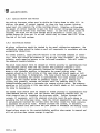
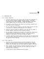
Test the operating characteristics of the KP relays as follows.
3.4.2.1
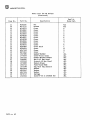
Recommended Test Equipment
NOMENCLATURE
PART/MODEL/TYPE NO.
Power Supply,, 0-40 Vdc
Digital Multimeter (two required)
DPDT (Double pole, double throw)
Switch
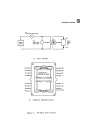
3.4.2.2 KP Biased Relay Test Procedure.
2, and proceed as follows:
HP6205B or equivalent
HP3435A or equivalent
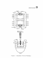
Connect the circuit as shown in figure
a.
Set Ml to appropriate current range.
b.
Set M2 to appropriate voltage range.
c.
Set DC power supply to appropriate output range.
d.
Set switch Sl to Normal.
e.
Turn DC power supply on.
f.
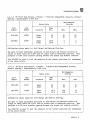
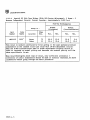
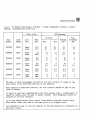
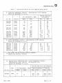
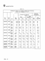
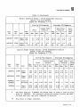
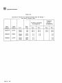
Observe Ml (Current Monitor) and adjust DC power supply output control
to charge the relay (Charge equals four times pick up or working), see
table II or III.
g.
Gradually reduce current until front contacts open.
dropaway value.
h.
Further decrease current, if necessary, until pins touch pole pieces.
This is the full dropaway value.
i,
Momentarily open circuit, then close it and gradually increase current
until relay closes its front contacts, This is the pick up value.
j.
Further increase current, if necessary, until the armature stop pins
touch the pole pieces. This is the working value.
k.
Test concluded. Disconnect test circuit, and return relay to its
original location.
3623 P• 10
This is the